2005 NISSAN NAVARA suspension
[x] Cancel search: suspensionPage 1606 of 3171
FSU-6
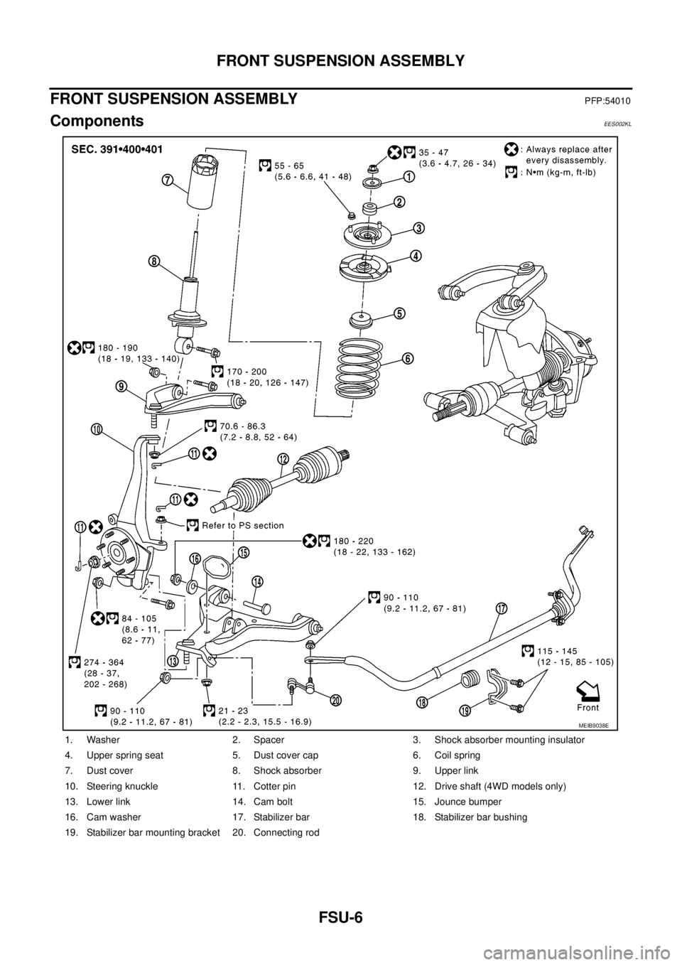
FRONT SUSPENSION ASSEMBLY
FRONT SUSPENSION ASSEMBLY
PFP:54010
ComponentsEES002KL
1. Washer 2. Spacer 3. Shock absorber mounting insulator
4. Upper spring seat 5. Dust cover cap 6. Coil spring
7. Dust cover 8. Shock absorber 9. Upper link
10. Steering knuckle 11. Cotter pin 12. Drive shaft (4WD models only)
13. Lower link 14. Cam bolt 15. Jounce bumper
16. Cam washer 17. Stabilizer bar 18. Stabilizer bar bushing
19. Stabilizer bar mounting bracket 20. Connecting rod
MEIB9038E
Page 1607 of 3171
ON-VEHICLE SERVICE
FSU-7
C
D
F
G
H
I
J
K
L
MA
B
FSU
ON-VEHICLE SERVICEPFP:00000
Front Suspension PartsEES002KM
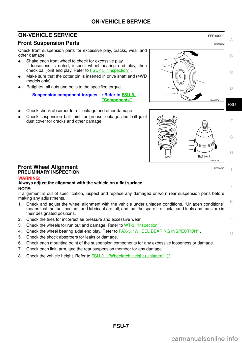
Check front suspension parts for excessive play, cracks, wear and
other damage.
lShake each front wheel to check for excessive play.
If looseness is noted, inspect wheel bearing end play, then
check ball joint end play. Refer toFSU-15, "
Inspection".
lMake sure that the cotter pin is inserted in drive shaft end (4WD
models only).
lRetighten all nuts and bolts to the specified torque.
lCheck shock absorber for oil leakage and other damage.
lCheck suspension ball joint for grease leakage and ball joint
dust cover for cracks and other damage.
Front Wheel AlignmentEES002KN
PRELIMINARY INSPECTION
WARNING:
Always adjust the alignment with the vehicle on a flat surface.
NOTE:
If alignment is out of specification, inspect and replace any damaged or worn rear suspension parts before
making any adjustments.
1. Check and adjust the wheel alignment with the vehicle under unladen conditions. “Unladen conditions”
means that the fuel, coolant, and lubricant are full; and that the spare tire, jack, hand tools and mats are in
their designated positions.
2. Check the tires for incorrect air pressure and excessive wear.
3. Check the wheels for run out and damage. Refer toWT-3, "
Inspection".
4. Check the wheel bearing axial end play. Refer toFA X - 5 , "
WHEEL BEARING INSPECTION".
5. Check the shock absorbers for leaks or damage.
6. Check each mounting point of the suspension components for any excessive looseness or damage.
7. Check each link, arm, and the rear suspension member for any damage.
8. Check the vehicle height. Refer toFSU-21, "
Wheelarch Height (Unladen*1)". Suspension component torques : Refer toFSU-6,
"Components".SMA525A
SFA392B
Page 1609 of 3171
ON-VEHICLE SERVICE
FSU-9
C
D
F
G
H
I
J
K
L
MA
B
FSU
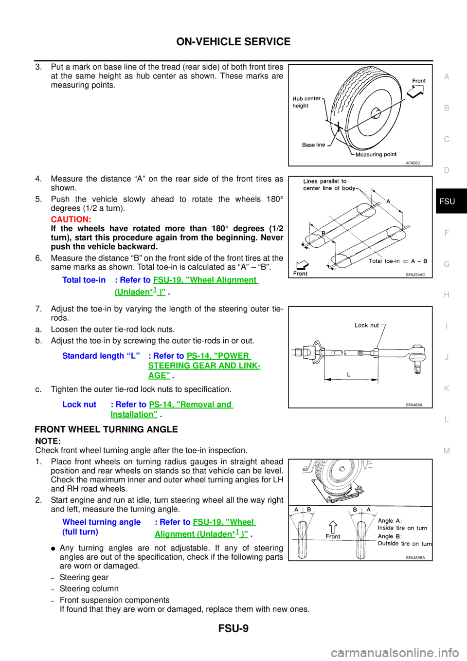
3. Put a mark on base line of the tread (rear side) of both front tires
at the same height as hub center as shown. These marks are
measuring points.
4. Measure the distance “A” on the rear side of the front tires as
shown.
5. Push the vehicle slowly ahead to rotate the wheels 180°
degrees (1/2 a turn).
CAUTION:
If the wheels have rotated more than 180°degrees (1/2
turn), start this procedure again from the beginning. Never
push the vehicle backward.
6. Measure the distance “B” on the front side of the front tires at the
same marks as shown. Total toe-in is calculated as “A” – “B”.
7. Adjust the toe-in by varying the length of the steering outer tie-
rods.
a. Loosen the outer tie-rod lock nuts.
b. Adjust the toe-in by screwing the outer tie-rods in or out.
c. Tighten the outer tie-rod lock nuts to specification.
FRONT WHEEL TURNING ANGLE
NOTE:
Check front wheel turning angle after the toe-in inspection.
1. Place front wheels on turning radius gauges in straight ahead
position and rear wheels on stands so that vehicle can be level.
Check the maximum inner and outer wheel turning angles for LH
and RH road wheels.
2. Start engine and run at idle, turn steering wheel all the way right
and left, measure the turning angle.
lAny turning angles are not adjustable. If any of steering
angles are out of the specification, check if the following parts
are worn or damaged.
–Steering gear
–Steering column
–Front suspension components
If found that they are worn or damaged, replace them with new ones.
AFA050
Total toe-in : Refer toFSU-19, "Wheel Alignment
(Unladen*1)".
SFA234AC
Standard length “L” : Refer toPS-14, "POWER
STEERING GEAR AND LINK-
AGE".
Lock nut : Refer toPS-14, "
Removal and
Installation".
SFA486A
Wheel turning angle
(full turn):RefertoFSU-19, "Wheel
Alignment (Unladen*1)".
SFA439BA
Page 1619 of 3171
SERVICE DATA AND SPECIFICATIONS (SDS)
FSU-19
C
D
F
G
H
I
J
K
L
MA
B
FSU
SERVICE DATA AND SPECIFICATIONS (SDS)PFP:00030
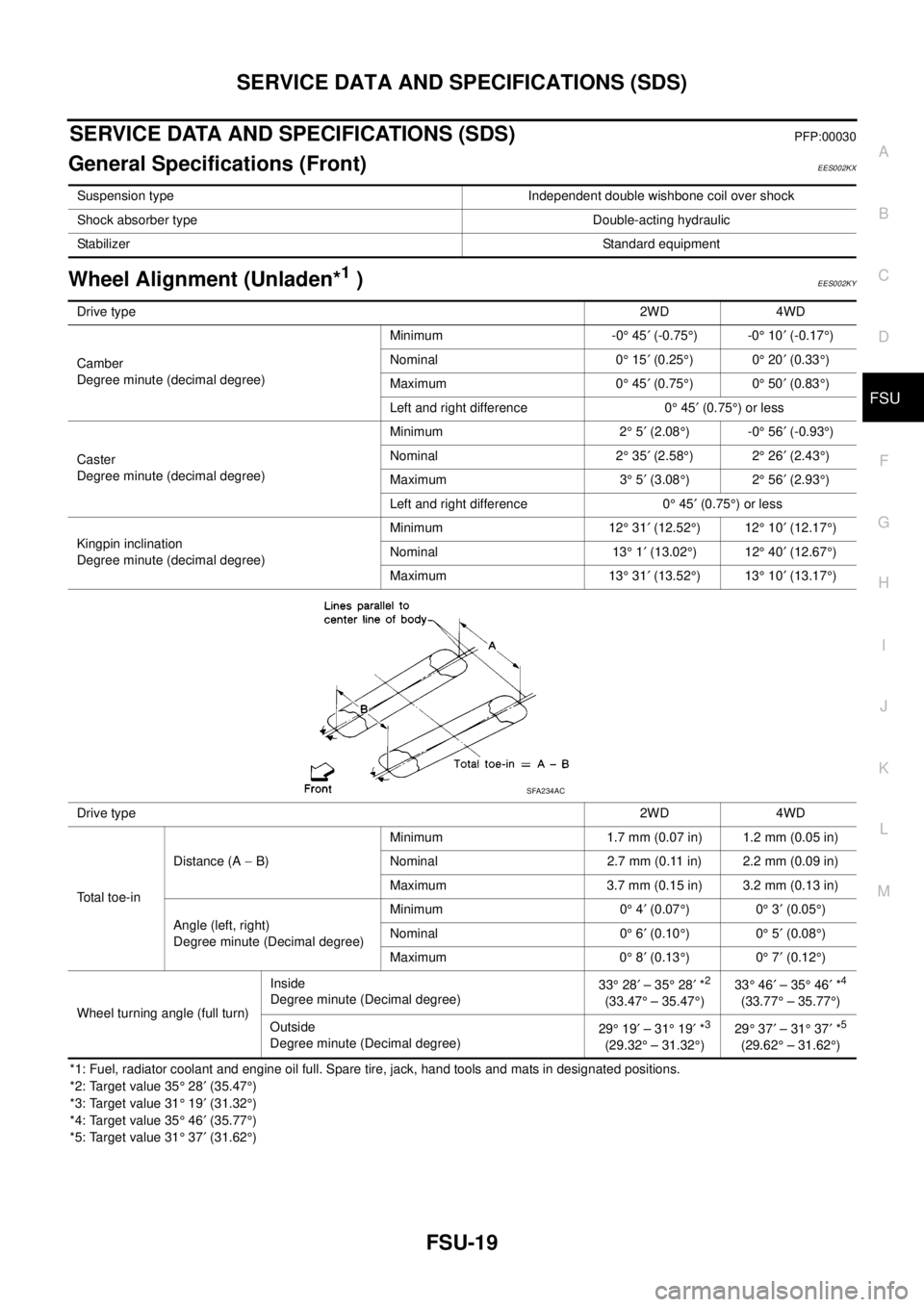
General Specifications (Front)EES002KX
Wheel Alignment (Unladen*1)EES002KY
*1: Fuel, radiator coolant and engine oil full. Spare tire, jack, hand tools and mats in designated positions.
*2: Target value 35°28¢(35.47°)
*3: Target value 31°19¢(31.32°)
*4: Target value 35°46¢(35.77°)
*5: Target value 31°37¢(31.62°) Suspension type Independent double wishbone coil over shock
Shock absorber type Double-acting hydraulic
StabilizerStandard equipment
Drive type2WD 4WD
Camber
Degree minute (decimal degree)Minimum -0°45¢(-0.75°)-0°10¢(-0.17°)
Nominal 0°15¢(0.25°)0°20¢(0.33°)
Maximum 0°45¢(0.75°)0°50¢(0.83°)
Left and right difference 0°45¢(0.75°)orless
Caster
Degree minute (decimal degree)Minimum 2°5¢(2.08°)-0°56¢(-0.93°)
Nominal 2°35¢(2.58°)2°26¢(2.43°)
Maximum 3°5¢(3.08°)2°56¢(2.93°)
Left and right difference 0°45¢(0.75°)orless
Kingpin inclination
Degree minute (decimal degree)Minimum 12°31¢(12.52°)12°10¢(12.17°)
Nominal 13°1¢(13.02°)12°40¢(12.67°)
Maximum 13°31¢(13.52°)13°10¢(13.17°)
Drive type2WD 4WD
Total toe-inDistance (A-B)Minimum 1.7 mm (0.07 in) 1.2 mm (0.05 in)
Nominal 2.7 mm (0.11 in) 2.2 mm (0.09 in)
Maximum 3.7 mm (0.15 in) 3.2 mm (0.13 in)
Angle (left, right)
Degree minute (Decimal degree)Minimum 0°4¢(0.07°)0°3¢(0.05°)
Nominal 0°6¢(0.10°)0°5¢(0.08°)
Maximum 0°8¢(0.13°)0°7¢(0.12°)
Wheel turning angle (full turn)Inside
Degree minute (Decimal degree)33°28¢–35°28¢*
2
(33.47°– 35.47°)33°46¢–35°46¢*
4
(33.77°– 35.77°)
Outside
Degree minute (Decimal degree)29°19¢–31°19¢*
3
(29.32°– 31.32°)29°37¢–31°37¢*
5
(29.62°– 31.62°)
SFA234AC
Page 1676 of 3171
GI-54
TOW TRUCK TOWING
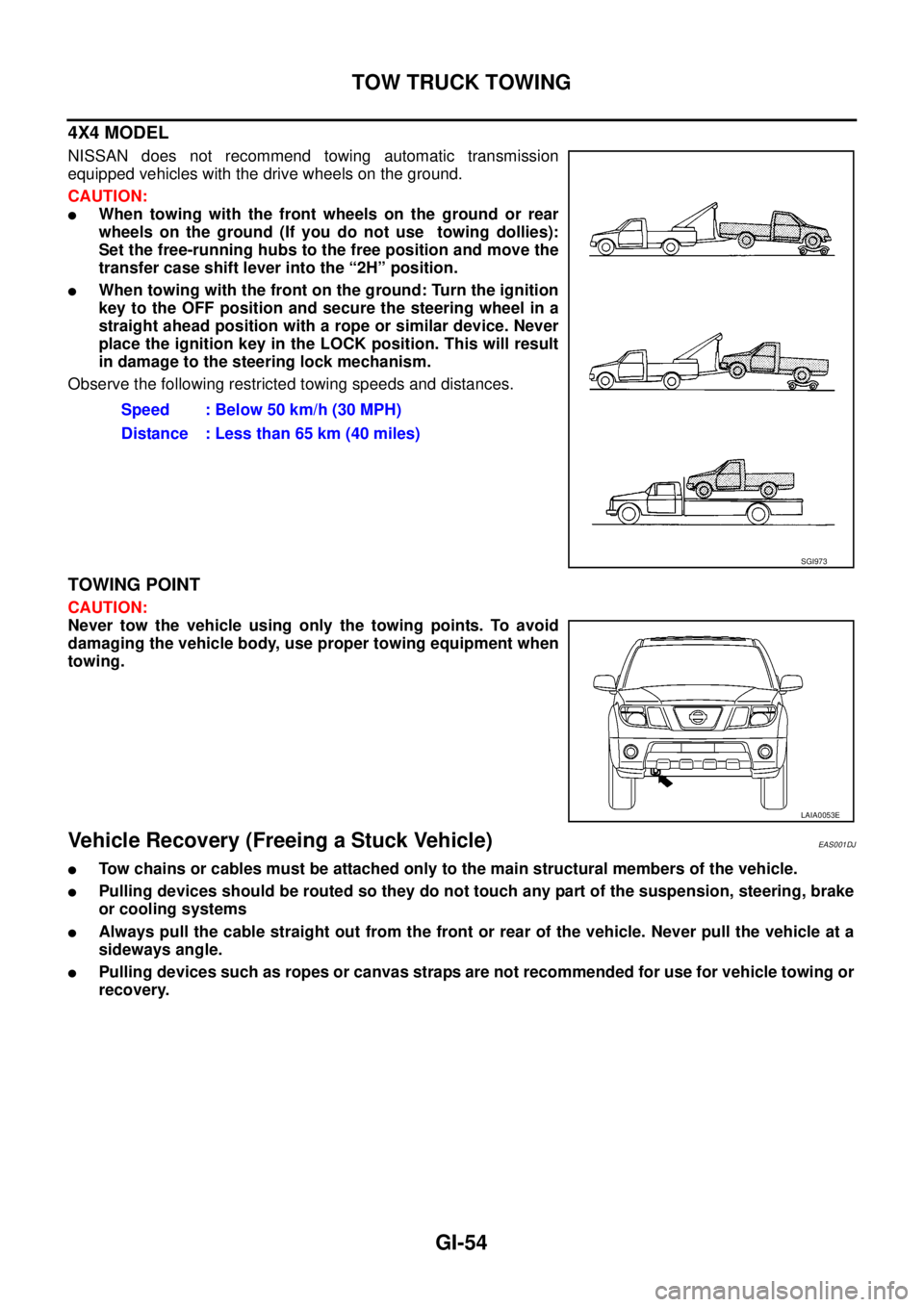
4X4 MODEL
NISSAN does not recommend towing automatic transmission
equipped vehicles with the drive wheels on the ground.
CAUTION:
lWhen towing with the front wheels on the ground or rear
wheels on the ground (If you do not use towing dollies):
Set the free-running hubs to the free position and move the
transfer case shift lever into the “2H” position.
lWhen towing with the front on the ground: Turn the ignition
key to the OFF position and secure the steering wheel in a
straight ahead position with a rope or similar device. Never
place the ignition key in the LOCK position. This will result
in damage to the steering lock mechanism.
Observe the following restricted towing speeds and distances.
TOWING POINT
CAUTION:
Never tow the vehicle using only the towing points. To avoid
damaging the vehicle body, use proper towing equipment when
towing.
Vehicle Recovery (Freeing a Stuck Vehicle)EAS001DJ
lTow chains or cables must be attached only to the main structural members of the vehicle.
lPulling devices should be routed so they do not touch any part of the suspension, steering, brake
or cooling systems
lAlways pull the cable straight out from the front or rear of the vehicle. Never pull the vehicle at a
sideways angle.
lPulling devices such as ropes or canvas straps are not recommended for use for vehicle towing or
recovery.Speed : Below 50 km/h (30 MPH)
Distance : Less than 65 km (40 miles)
SGI973
LAIA0053E
Page 2277 of 3171

MA-2
Checking Rear Final Drive Oil (Rear Differential
Gear Oil) ................................................................. 33
OIL LEAKAGE AND OIL LEVEL ......................... 33
Changing Rear Final Drive Oil (Rear Differential
Gear Oil) ................................................................. 34
DRAINING ........................................................... 34
FILLING ............................................................... 34
Balancing Wheels ................................................... 34
Tire Rotation ........................................................... 34
Checking Brake Fluid Level and Leaks .................. 35
Checking Brake Lines and Cables ......................... 35
Changing Brake Fluid ............................................. 35
Checking Disc Brake .............................................. 35
ROTOR ................................................................ 35
CALIPER ............................................................. 36
PAD ..................................................................... 36
Checking Drum Brake ............................................ 36
DRUM .................................................................. 36
WHEEL CYLINDER ............................................. 36
LINING ................................................................. 37
Checking Steering Gear and Linkage ..................... 37
STEERING GEAR ............................................... 37
STEERING LINKAGE .......................................... 37
Checking Power Steering Fluid and Lines .............. 37CHECKING FLUID LEVEL .................................. 37
CHECKING LINES ............................................... 37
Checking Axle and Suspension Parts ..................... 38
FRONT AND REAR AXLE AND SUSPENSION
PARTS ................................................................. 38
FRONT DRIVE SHAFT ........................................ 38
Lubricating Locks, Hinges and Hood Latches ......... 39
Checking Seat Belts, Buckles, Retractors, Anchors
and Adjusters .......................................................... 40
Checking Body Corrosion ....................................... 40
HEMMED PANELS .............................................. 40
PANEL JOINT ...................................................... 40
PANEL EDGE ...................................................... 40
PARTS CONTACT ............................................... 40
PROTECTORS .................................................... 40
ANTI-CORROSION MATERIALS ........................ 40
DRAIN HOLES ..................................................... 40
SERVICE DATA AND SPECIFICATIONS (SDS) ...... 41
Standard and Limit .................................................. 41
BELT DEFLECTION ............................................ 41
RESERVOIR TANK ............................................. 41
ENGINE COOLANT CAPACITY (APPROXI-
MATE) .................................................................. 41
ENGINE OIL CAPACITY (APPROXIMATE) ........ 41
Page 2280 of 3171
DESCRIPTION
MA-5
C
D
E
F
G
H
I
J
K
MA
B
MA
DESCRIPTIONPFP:00000
Pre-Delivery Inspection ItemsELS001K2
Shown below are Pre-delivery Inspection Items required for the new vehicle. It is recommended that
necessary items other than those listed here be added, paying due regard to the conditions in each
country.
Perform applicable items on each model. Consult text of this section for specifications.
Install vehicle protection kit
Fit all accessories ordered (if applicable) (e.g. towbar, audio, navigation, air conditioner, styling kit)
UNDER HOOD — engine off
Check coolant level and cooling system for leaks
Charge battery and check terminals for condition
Check drive belts tension
Check fuel filter for water or dust (diesel only) and fuel system for leaks
Check engine oil level and for oil leaks
Check brake and clutch fluid levels and fluid lines for leaks
Check and top up washer reservoirs
Check power steering fluid level and fluid lines for leaks (if applicable)
Check air conditioning system for gas leaks (if applicable)
ON INSIDE AND OUTSIDE
Install transit fuse if removed for vehicle storage
Check instruments, gauges, lamps, horn and accessories for operation
Check wipers and washers for operation and adjustment
Check interior and door mirrors and sun visors for operation
Set radio code and set clock
Check parking brake adjustment
Check clutch pedal adjustment
Check steering lock operation
Check seat adjusters and seat belts for operation
Check all windows for operation and alignment
Check mouldings, trim and fittings for fit and alignment
Check weatherstrips for fit and adhesion
Check hood, trunk lid, door panels and fuel lid for fit and alignment
Check latches, keys, remote key, door locks and remote trunk lid and fuel lid release for operation
Check wheel nut torques
Check tyre pressure (incl. spare tyre)
Check tool kit and jack for operation
Check automatic transmission/transaxle starter inhibitor (if applicable)
Check sunroof for operation and alignment (if applicable)
UNDER BODY
Check manual transmission/transaxle, differential and transfer box for oil level and oil leaks
Tighten bolts and nuts steering linkage and gear box, axle/suspension parts, propeller and exhaust system
Check brake and clutch lines, and oil/fluid reservoirs for leaks
Remove front suspension spacer blocks (if applicable)
Check body mounting torque (if applicable)
Page 2281 of 3171
MA-6
DESCRIPTION
ROAD TEST
Check clutch operation
Check foot brake operation
Check parking brake operation
Check steering operation, self-centering and steering wheel alignment
Check engine performance
Check for squeaks, rattles and noise from interior, suspension and brakes
Check heating, ventilation and air conditioning operation
Check radio, cassette and CD player operation
Check odometer and trip meter operation and cancelling
Check instruments for operation
Check automatic transmission/transaxle shift pattern and kickdown operation (if applicable)
Check cruise control and navigation system operation (if applicable)
ENGINE OPERATING AND HOT
Check idle speed
Check automatic transmission/transaxle oil level (if applicable)
FINAL INSPECTION
Remove vehicle protection kit
Fit interior mats and wheel covers
Check for interior and exterior metal and paint damage
Wash, clean interior and exterior
: Not applicable to this model