2005 NISSAN NAVARA load capacity
[x] Cancel search: load capacityPage 893 of 3171

ENGINE COOLANT
CO-9
C
D
E
F
G
H
I
J
K
L
MA
CO
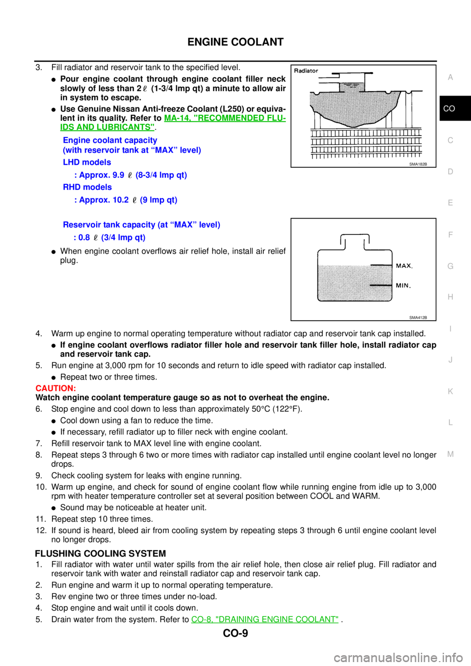
3. Fill radiator and reservoir tank to the specified level.
lPour engine coolant through engine coolant filler neck
slowly of less than 2 (1-3/4 lmp qt) a minute to allow air
in system to escape.
lUse Genuine Nissan Anti-freeze Coolant (L250) or equiva-
lent in its quality. Refer toMA-14, "
RECOMMENDED FLU-
IDS AND LUBRICANTS".
lWhen engine coolant overflows air relief hole, install air relief
plug.
4. Warm up engine to normal operating temperature without radiator cap and reservoir tank cap installed.
lIf engine coolant overflows radiator filler hole and reservoir tank filler hole, install radiator cap
and reservoir tank cap.
5. Run engine at 3,000 rpm for 10 seconds and return to idle speed with radiator cap installed.
lRepeat two or three times.
CAUTION:
Watch engine coolant temperature gauge so as not to overheat the engine.
6. Stop engine and cool down to less than approximately 50°C(122°F).
lCool down using a fan to reduce the time.
lIf necessary, refill radiator up to filler neck with engine coolant.
7. Refill reservoir tank to MAX level line with engine coolant.
8. Repeat steps 3 through 6 two or more times with radiator cap installed until engine coolant level no longer
drops.
9. Check cooling system for leaks with engine running.
10. Warm up engine, and check for sound of engine coolant flow while running engine from idle up to 3,000
rpm with heater temperature controller set at several position between COOL and WARM.
lSound may be noticeable at heater unit.
11. Repeat step 10 three times.
12. If sound is heard, bleed air from cooling system by repeating steps 3 through 6 until engine coolant level
no longer drops.
FLUSHING COOLING SYSTEM
1. Fill radiator with water until water spills from the air relief hole, then close air relief plug. Fill radiator and
reservoir tank with water and reinstall radiator cap and reservoir tank cap.
2. Run engine and warm it up to normal operating temperature.
3. Rev engine two or three times under no-load.
4. Stop engine and wait until it cools down.
5. Drain water from the system. Refer toCO-8, "
DRAINING ENGINE COOLANT". Engine coolant capacity
(with reservoir tank at “MAX” level)
LHD models
: Approx. 9.9 (8-3/4 lmp qt)
RHD models
: Approx. 10.2 (9 lmp qt)
SMA182B
Reservoir tank capacity (at “MAX” level)
: 0.8 (3/4 lmp qt)
SMA412B
Page 1583 of 3171

SERVICE DATA AND SPECIFICATIONS (SDS)
FFD-37
C
E
F
G
H
I
J
K
L
MA
B
FFD
SERVICE DATA AND SPECIFICATIONS (SDS)PFP:00030
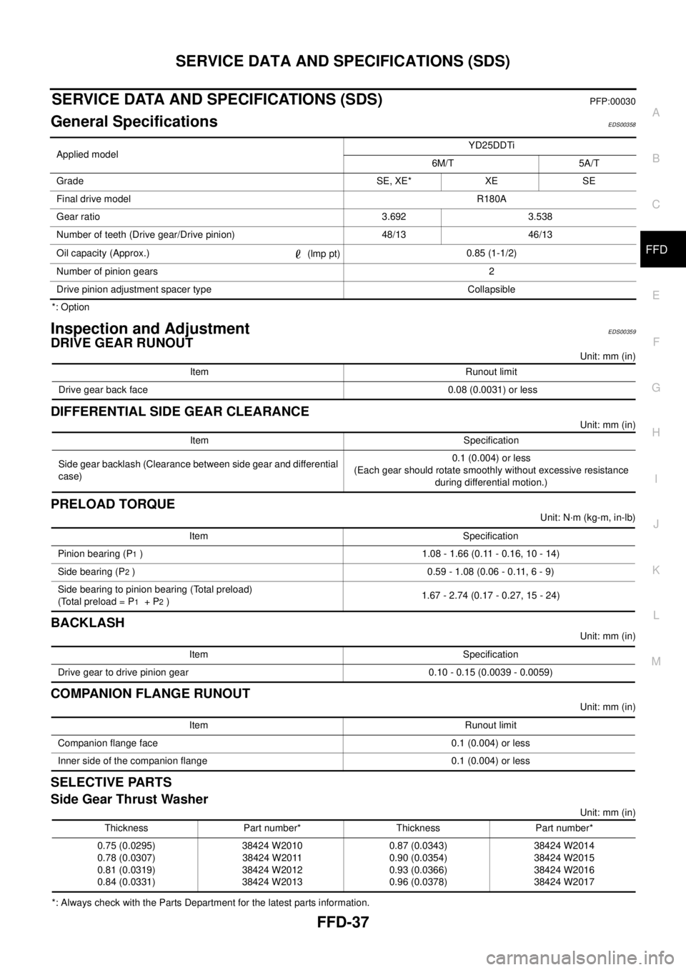
General SpecificationsEDS00358
*: Option
Inspection and AdjustmentEDS00359
DRIVE GEAR RUNOUT
Unit: mm (in)
DIFFERENTIAL SIDE GEAR CLEARANCE
Unit: mm (in)
PRELOAD TORQUE
Unit: N·m (kg-m, in-lb)
BACKLASH
Unit: mm (in)
COMPANION FLANGE RUNOUT
Unit: mm (in)
SELECTIVE PARTS
Side Gear Thrust Washer
Unit: mm (in)
*: Always check with the Parts Department for the latest parts information.Applied modelYD25DDTi
6M/T 5A/T
Grade SE, XE* XE SE
Final drive modelR180A
Gear ratio 3.692 3.538
Number of teeth (Drive gear/Drive pinion) 48/13 46/13
Oil capacity (Approx.)
(lmp pt)0.85 (1-1/2)
Number of pinion gears2
Drive pinion adjustment spacer type Collapsible
Item Runout limit
Drive gear back face 0.08 (0.0031) or less
Item Specification
Side gear backlash (Clearance between side gear and differential
case)0.1 (0.004) or less
(Each gear should rotate smoothly without excessive resistance
during differential motion.)
Item Specification
Pinion bearing (P
1) 1.08 - 1.66 (0.11 - 0.16, 10 - 14)
Side bearing (P
2) 0.59 - 1.08 (0.06 - 0.11, 6 - 9)
Side bearing to pinion bearing (Total preload)
(Total preload = P
1+P2)1.67 - 2.74 (0.17 - 0.27, 15 - 24)
Item Specification
Drive gear to drive pinion gear 0.10 - 0.15 (0.0039 - 0.0059)
Item Runout limit
Companion flange face 0.1 (0.004) or less
Inner side of the companion flange 0.1 (0.004) or less
Thickness Part number* Thickness Part number*
0.75 (0.0295)
0.78 (0.0307)
0.81 (0.0319)
0.84 (0.0331)38424 W2010
38424 W2011
38424 W2012
38424 W20130.87 (0.0343)
0.90 (0.0354)
0.93 (0.0366)
0.96 (0.0378)38424 W2014
38424 W2015
38424 W2016
38424 W2017
Page 2734 of 3171
![NISSAN NAVARA 2005 Repair Workshop Manual SERVICE DATA AND SPECIFICATIONS (SDS)
RFD-31
[WITH LIMITED SLIP DIFFERENTIAL]
C
E
F
G
H
I
J
K
L
MA
B
RFD
SERVICE DATA AND SPECIFICATIONS (SDS)PFP:00030
General SpecificationsEDS0039A
*: Option
Inspect NISSAN NAVARA 2005 Repair Workshop Manual SERVICE DATA AND SPECIFICATIONS (SDS)
RFD-31
[WITH LIMITED SLIP DIFFERENTIAL]
C
E
F
G
H
I
J
K
L
MA
B
RFD
SERVICE DATA AND SPECIFICATIONS (SDS)PFP:00030
General SpecificationsEDS0039A
*: Option
Inspect](/manual-img/5/57362/w960_57362-2733.png)
SERVICE DATA AND SPECIFICATIONS (SDS)
RFD-31
[WITH LIMITED SLIP DIFFERENTIAL]
C
E
F
G
H
I
J
K
L
MA
B
RFD
SERVICE DATA AND SPECIFICATIONS (SDS)PFP:00030
General SpecificationsEDS0039A
*: Option
Inspection and AdjustmentEDS0039B
PRELOAD TORQUE
Unit: N·m (kg-m, in-lb)
BACKLASH
Unit: mm (in)
COMPANION FLANGE RUNOUT
Unit: mm (in) Applied modelYD25DDTi
2WD 4WD
6M/T 5A/T 6M/T 5A/T
Grade SE, XE SE SE, XE* XE SE
Final drive modelM226
Gear ratio 3.538 3.357 3.692 3.538
Number of pinion gears 2
Number of teeth (Drive gear / drive pinion) 46/13 47/14 48/13 46/13
Oil capacity (Approx.)
(lmp pt)2.01 (3-1/2)
Drive pinion adjustment spacer type Collapsible
ItemSpecification
Gear ratio 3.357 type Gear ratio 3.538 type Gear ratio 3.692 type
To t a l p r e l o a d2.38 - 4.46
(0.25-0.45,21-39)2.34 - 4.34
(0.24 - 0.44, 21 - 38)2.32 - 4.34
(0.24 - 0.44, 21 - 38)
Pinion bearing preload 1.7 - 3.1 (0.18 - 0.31, 15 - 27)
Item Standard
Drive gear to drive pinion gear 0.08 - 0.13 (0.0031 - 0.0051)
Item Runout limit
Companion flange face 0.10 (0.0039) or less
Inner side of companion flange 0.13 (0.0051) or less
Page 2803 of 3171
![NISSAN NAVARA 2005 Repair Workshop Manual RFD-100
[WITH ELECTRONIC LOCKING DIFFERENTIAL]
SERVICE DATA AND SPECIFICATIONS (SDS)
SERVICE DATA AND SPECIFICATIONS (SDS)
PFP:00030
General SpecificationsEDS003BH
Inspection and AdjustmentEDS003BI
PR NISSAN NAVARA 2005 Repair Workshop Manual RFD-100
[WITH ELECTRONIC LOCKING DIFFERENTIAL]
SERVICE DATA AND SPECIFICATIONS (SDS)
SERVICE DATA AND SPECIFICATIONS (SDS)
PFP:00030
General SpecificationsEDS003BH
Inspection and AdjustmentEDS003BI
PR](/manual-img/5/57362/w960_57362-2802.png)
RFD-100
[WITH ELECTRONIC LOCKING DIFFERENTIAL]
SERVICE DATA AND SPECIFICATIONS (SDS)
SERVICE DATA AND SPECIFICATIONS (SDS)
PFP:00030
General SpecificationsEDS003BH
Inspection and AdjustmentEDS003BI
PRELOAD TORQUE
Unit: N·m (kg-m, in-lb)
BACKLASH
Unit: mm (in)
COMPANION FLANGE RUNOUT
Unit: mm (in) Applied modelYD25DDTi
4WD
5A/T 6M/T
Final drive modelM226
Gear ratio 3.538 3.692
Number of pinion gears 2
Number of teeth (Drive gear / drive pinion) 46/13 48/13
Oil capacity (Approx.)
(lmp pt)2.01 (3-1/2)
Drive pinion adjustment spacer type Collapsible
ItemStandard
Gear ratio: 3.538 type Gear ratio: 3.692 type
Total preload 2.34 - 4.34 (0.24 - 0.44, 21 - 38) 2.32 - 4.34 (0.24 - 0.44, 21 - 38)
Pinion bearing preload 1.7 - 3.1 (0.18 - 0.31, 15 - 27)
Item Standard
Drive gear to drive pinion gear 0.08 - 0.13 (0.0031 - 0.0051)
Item Runout limit
Companion flange face 0.10 (0.0039) or less
Inner side of companion flange 0.13 (0.0051) or less
Page 2870 of 3171

SERVICE DATA AND SPECIFICATIONS (SDS)
SC-37
C
D
E
F
G
H
I
J
L
MA
B
SC
SERVICE DATA AND SPECIFICATIONS (SDS)PFP:00030
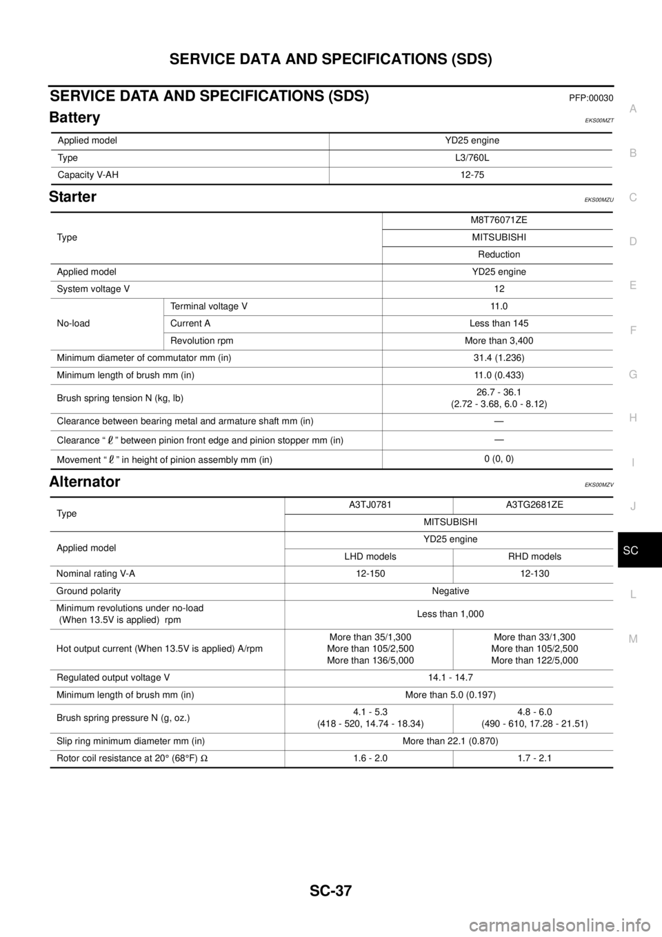
BatteryEKS00MZT
StarterEKS00MZU
AlternatorEKS00MZV
Applied modelYD25 engine
TypeL3/760L
Capacity V-AH12-75
Ty p eM8T76071ZE
MITSUBISHI
Reduction
Applied modelYD25 engine
System voltage V12
No-loadTerminal voltage V 11.0
Current A Less than 145
Revolution rpm More than 3,400
Minimum diameter of commutator mm (in) 31.4 (1.236)
Minimum length of brush mm (in) 11.0 (0.433)
Brush spring tension N (kg, lb)26.7 - 36.1
(2.72 - 3.68, 6.0 - 8.12)
Clearance between bearing metal and armature shaft mm (in) —
Clearance “ ” between pinion front edge and pinion stopper mm (in)—
Movement “ ” in height of pinion assembly mm (in)0 (0, 0)
TypeA3TJ0781 A3TG2681ZE
MITSUBISHI
Applied modelYD25 engine
LHD models RHD models
Nominal rating V-A 12-150 12-130
Ground polarityNegative
Minimum revolutions under no-load
(When 13.5V is applied) rpmLess than 1,000
Hot output current (When 13.5V is applied) A/rpmMore than 35/1,300
More than 105/2,500
More than 136/5,000More than 33/1,300
More than 105/2,500
More than 122/5,000
Regulated output voltage V 14.1 - 14.7
Minimum length of brush mm (in) More than 5.0 (0.197)
Brush spring pressure N (g, oz.)4.1 - 5.3
(418 - 520, 14.74 - 18.34)4.8 - 6.0
(490 - 610, 17.28 - 21.51)
Slip ring minimum diameter mm (in) More than 22.1 (0.870)
Rotor coil resistance at 20°(68°F)W1.6 - 2.0 1.7 - 2.1