2005 NISSAN NAVARA clock
[x] Cancel search: clockPage 257 of 3171

TRANSMISSION ASSEMBLY
AT-249
D
E
F
G
H
I
J
K
L
MA
B
AT
5. Remove front valance center, engine undercover front, engine under cover middle and engine under
coverrear.RefertoEI-15, "
FRONT BUMPER".
6. Remove front cross member.
7. Remove main muffler. Refer toEX-2, "
EXHAUST SYSTEM".
8. Remove rear propeller shaft. Refer toPR-8, "
Removal and Installation".
9. Remove front propeller shaft. Refer toPR-4, "
Removal and Installation".
10. Remove starter motor. Refer toSC-31, "
Removal and Installation".
11. Remove control cable and bracket. Refer toAT- 2 1 0 , "
Control Cable Removal and Installation".
12. Disconnect fluid cooler tube.
13. Remove A/T fluid charging pipe from A/T assembly.
14. Remove O-ring from A/T fluid charging pipe.
15. Plug up openings such as A/T fluid charging pipe hole, etc.
16. Remove rear plate cover from rear plate.
17. Turn crankshaft to access and remove the four bolts for drive
plate and torque converter.
CAUTION:
When turning crankshaft, turn it clockwise as viewed from
the front of engine.
18. Support A/T assembly using a transmission jack.
CAUTION:
When setting transmission jack, be careful not to allow it to
collide against drain plug.
19. Remove protector (fuel tube), and then disconnect fuel tubes.
Refer toFL-7, "
FUEL COOLER". (4WD models)
20. Remove A/T cross member.
21. Remove engine mounting insulator (rear) from A/T assembly.
22. Disconnect the following:
lA/T assembly harness connector
lATP switch connector
l4LO switch connector
lWait detection switch connector
lTransfer control device connector
23. Support transfer assembly using a transmission jack. (4WD models)
24. Remove the wiring harness from bracket.
25. Remove bolts fixing A/T assembly to engine assembly.
26. Remove A/T assembly from the vehicle.
CAUTION:
lSecure torque converter to prevent it from dropping.
lSecure A/T assembly to a transmission jack.
27. Remove A/T air breather hose. Refer toAT- 2 4 3 , "
AIR
BREATHER HOSE".
28. Remove transfer assembly from A/T assembly. Refer toT F - 111 ,
"Removal and Installation". (4WD models)
SCIA6828E
SCIA6927E
SCIA2203E
Page 258 of 3171

AT-250
TRANSMISSION ASSEMBLY
INSPECTION
Installation and Inspection of Torque Converter
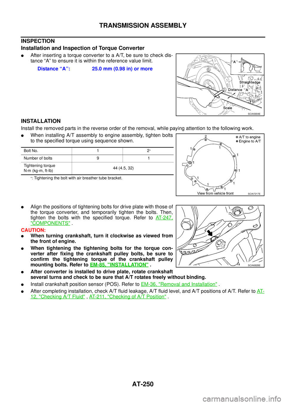
lAfter inserting a torque converter to a A/T, be sure to check dis-
tance “A” to ensure it is within the reference value limit.
INSTALLATION
Install the removed parts in the reverse order of the removal, while paying attention to the following work.
lWhen installing A/T assembly to engine assembly, tighten bolts
to the specified torque using sequence shown.
*: Tightening the bolt with air breather tube bracket.
lAlign the positions of tightening bolts for drive plate with those of
the torque converter, and temporarily tighten the bolts. Then,
tighten the bolts with the specified torque. Refer toAT-247,
"COMPONENTS".
CAUTION:
lWhen turning crankshaft, turn it clockwise as viewed from
the front of engine.
lWhen tightening the tightening bolts for the torque con-
verter after fixing the crankshaft pulley bolts, be sure to
confirm the tightening torque of the crankshaft pulley
mounting bolts. Refer toEM-85, "
INSTALLATION".
lAfter converter is installed to drive plate, rotate crankshaft
several turns and check to be sure that A/T rotates freely without binding.
lInstall crankshaft position sensor (POS). Refer toEM-36, "Removal and Installation".
lAfter completing installation, check A/T fluid leakage, A/T fluid level, and A/T positions of A/T. Refer toAT-
12, "Checking A/T Fluid",AT- 2 11 , "Checking of A/T Position". Distance “A”: 25.0 mm (0.98 in) or more
SCIA5694E
Bolt No. 1 2*
Number of bolts 9 1
Tightening torque
N·m (kg-m, ft-lb)44 (4.5, 32)
SCIA7217E
SCIA6828E
Page 271 of 3171

DISASSEMBLY
AT-263
D
E
F
G
H
I
J
K
L
MA
B
AT
DISASSEMBLYPFP:31020
DisassemblyECS00G3E
CAUTION:
Do not disassemble parts behind drum support. Refer toAT-14, "
Cross-Sectional View (2WD Models)"
,AT-15, "Cross-Sectional View (4WD Models)".
1. Drain ATF through drain hole.
2. Remove torque converter by holding it firmly and turing while
pulling straight out.
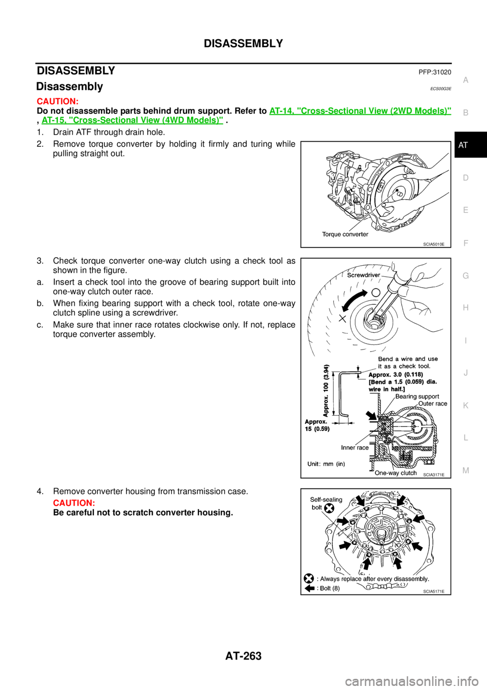
3. Check torque converter one-way clutch using a check tool as
showninthefigure.
a. Insert a check tool into the groove of bearing support built into
one-way clutch outer race.
b. When fixing bearing support with a check tool, rotate one-way
clutch spline using a screwdriver.
c. Make sure that inner race rotates clockwise only. If not, replace
torque converter assembly.
4. Remove converter housing from transmission case.
CAUTION:
Be careful not to scratch converter housing.
SCIA5010E
SCIA3171E
SCIA5171E
Page 348 of 3171

ATC-14
PRECAUTIONS
SERVICE COUPLERS
Never attempt to connect HFC-134a (R-134a) service couplers to an
CFC-12 (R-12) A/C system. The HFC-134a (R-134a) couplers will
not properly connect to the CFC-12 (R-12) system. However, if an
improper connection is attempted, discharging and contamination
may occur.
REFRIGERANT WEIGHT SCALE
Verify that no refrigerant other than HFC-134a (R-134a) and speci-
fied lubricants have been used with the scale. If the scale controls
refrigerant flow electronically, the hose fitting must be 1/2²-16
ACME.
CALIBRATING ACR4 WEIGHT SCALE
Calibrate the scale every three months.
To calibrate the weight scale on the ACR4:
1. Press “Shift/Reset”and“Enter”at the same time.
2. Press “8787”.“A1” will be displayed.
3. Remove all weight from the scale.
4. Press “0”, then press “Enter”.“0.00” will be displayed and change to “A2”.
5. Place a known weight (dumbbell or similar weight), between 4.5 and 8.6 kg (10 and 19 lb.) on the center
of the weight scale.
6. Enter the known weight using four digits. (Example 10 lb. = 10.00, 10.5 lb. = 10.50)
7. Press “Enter”— the display returns to the vacuum mode.
8. Press“Shift/Reset”and“Enter”at the same time.
9. Press “6” — the known weight on the scale is displayed.
10. Remove the known weight from the scale. “0.00” will be displayed.
11. Press“Shift/Reset” to return the ACR4 to the program mode.
CHARGING CYLINDER
Using a charging cylinder is not recommended. Refrigerant may be vented into air from cylinder’s top valve
when filling the cylinder with refrigerant. Also, the accuracy of the cylinder is generally less than that of an
electronic scale or of quality recycle/recharge equipment.
Precautions for Leak Detection DyeEJS006AR
lThe A/C system contains a fluorescent leak detection dye used for locating refrigerant leaks. An ultraviolet
(UV) lamp is required to illuminate the dye when inspecting for leaks.
lAlways wear fluorescence enhancing UV safety goggles to protect your eyes and enhance the visibility of
the fluorescent dye.
lThe fluorescent dye leak detector is not a replacement for an electronic refrigerant leak detector. The fluo-
rescent dye leak detector should be used in conjunction with an electronic refrigerant leak detector (J-
41995) to pin-point refrigerant leaks.
lFor your safety and your customer’s satisfaction, read and follow all manufacture’s operating instructions
and precautions prior to performing the work.
Shut-off valve rotation A/C service valve
Clockwise Open
Counterclockwise Close
RHA273D
RHA274D
Page 387 of 3171

TROUBLE DIAGNOSIS
ATC-53
C
D
E
F
G
H
I
K
L
MA
B
AT C
Front Air Control Terminals and Reference ValueEJS006BF
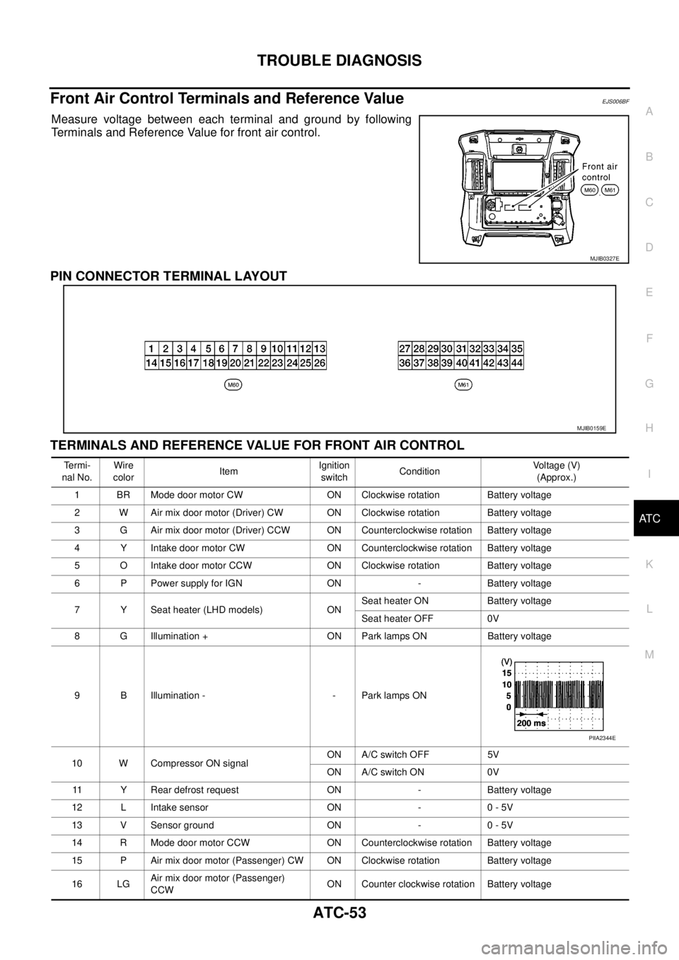
Measure voltage between each terminal and ground by following
Terminals and Reference Value for front air control.
PIN CONNECTOR TERMINAL LAYOUT
TERMINALS AND REFERENCE VALUE FOR FRONT AIR CONTROL
MJIB0327E
MJIB0159E
Te r m i -
nal No.Wire
colorItemIgnition
switchConditionVo l ta g e (V )
(Approx.)
1 BR Mode door motor CW ON Clockwise rotation Battery voltage
2 W Air mix door motor (Driver) CW ON Clockwise rotation Battery voltage
3 G Air mix door motor (Driver) CCW ON Counterclockwise rotation Battery voltage
4 Y Intake door motor CW ON Counterclockwise rotation Battery voltage
5 O Intake door motor CCW ON Clockwise rotation Battery voltage
6 P Power supply for IGN ON - Battery voltage
7 Y Seat heater (LHD models) ONSeat heater ON Battery voltage
Seat heater OFF 0V
8 G Illumination + ON Park lamps ON Battery voltage
9 B Illumination - - Park lamps ON
10 W Compressor ON signalON A/C switch OFF 5V
ON A/C switch ON 0V
11 Y Rear defrost request ON - Battery voltage
12 L Intake sensor ON - 0 - 5V
13 V Sensor ground ON - 0 - 5V
14 R Mode door motor CCW ON Counterclockwise rotation Battery voltage
15 P Air mix door motor (Passenger) CW ON Clockwise rotation Battery voltage
16 LGAir mix door motor (Passenger)
CCWON Counter clockwise rotation Battery voltage
PIIA2344E
Page 391 of 3171

TROUBLE DIAGNOSIS
ATC-57
C
D
E
F
G
H
I
K
L
MA
B
AT C
Operational CheckEJS006BH
The purpose of the operational check is to confirm that the system operates properly.
CHECKING MEMORY FUNCTION
1. Set the temperature to 32°C(90°F).
2. Turn blower control dial counterclockwise until system shuts
OFF.
3. Turn ignition switch OFF.
4. Turn ignition switch ON.
5. Press the AUTO switch.
6. Confirm that the set temperature remains at previous tempera-
ture.
7. Turn blower control dial counterclockwise until system shuts
OFF.
If NG, go to trouble diagnosis procedure forATC-104, "
Memory
Function".
If OK, continue with next check.
CHECKING BLOWER
1. Press the AUTO switch. Blower should operate on low speed.
The blower symbol should have one blade lit (on display).
2. Turn the blower control dial again, and continue checking blower
speed and blower symbol until all speeds are checked.
3. Leave blower on MAX speed.
If NG, go to trouble diagnosis procedure forAT C - 8 2 , "
DIAGNOSTIC
PROCEDURE FOR BLOWER MOTOR".
If OK, continue with next check.Conditions : Engine running and at normal operating temperature
MJIB0335E
MJIB0336E
MJIB0335E
MJIB0337E
Page 392 of 3171

ATC-58
TROUBLE DIAGNOSIS
CHECKING DISCHARGE AIR
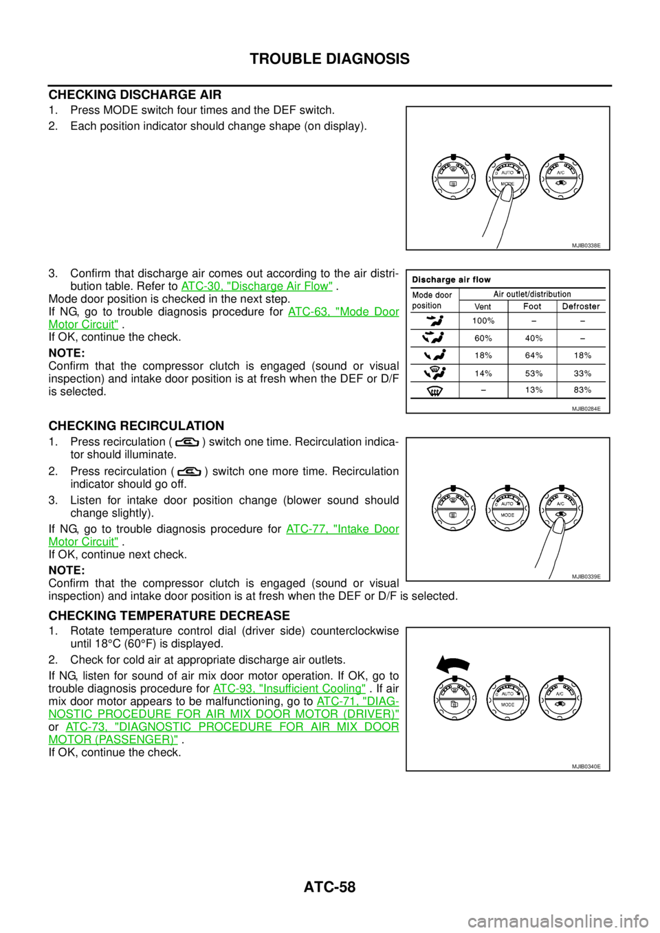
1. Press MODE switch four times and the DEF switch.
2. Each position indicator should change shape (on display).
3. Confirm that discharge air comes out according to the air distri-
bution table. Refer toAT C - 3 0 , "
Discharge Air Flow".
Mode door position is checked in the next step.
If NG, go to trouble diagnosis procedure forAT C - 6 3 , "
Mode Door
Motor Circuit".
If OK, continue the check.
NOTE:
Confirm that the compressor clutch is engaged (sound or visual
inspection) and intake door position is at fresh when the DEF or D/F
is selected.
CHECKING RECIRCULATION
1. Press recirculation ( ) switch one time. Recirculation indica-
tor should illuminate.
2. Press recirculation ( ) switch one more time. Recirculation
indicator should go off.
3. Listen for intake door position change (blower sound should
change slightly).
If NG, go to trouble diagnosis procedure forAT C - 7 7 , "
Intake Door
Motor Circuit".
If OK, continue next check.
NOTE:
Confirm that the compressor clutch is engaged (sound or visual
inspection) and intake door position is at fresh when the DEF or D/F is selected.
CHECKING TEMPERATURE DECREASE
1. Rotate temperature control dial (driver side) counterclockwise
until 18°C(60°F) is displayed.
2. Check for cold air at appropriate discharge air outlets.
If NG, listen for sound of air mix door motor operation. If OK, go to
trouble diagnosis procedure forAT C - 9 3 , "
Insufficient Cooling".Ifair
mix door motor appears to be malfunctioning, go toAT C - 7 1 , "
DIAG-
NOSTIC PROCEDURE FOR AIR MIX DOOR MOTOR (DRIVER)"
orAT C - 7 3 , "DIAGNOSTIC PROCEDURE FOR AIR MIX DOOR
MOTOR (PASSENGER)".
If OK, continue the check.
MJIB0338E
MJIB0284E
MJIB0339E
MJIB0340E
Page 393 of 3171

TROUBLE DIAGNOSIS
ATC-59
C
D
E
F
G
H
I
K
L
MA
B
AT C
CHECKING TEMPERATURE INCREASE
1. Rotate temperature control dial clockwise (driver side) until 32°C
(90°F) is displayed.
2. Check for hot air at appropriate discharge air outlets.
If NG, listen for sound of air mix door motor operation. If OK, go to
trouble diagnosis procedure forATC-100, "
Insufficient Heating".If
air mix door motor appears to be malfunctioning, go toAT C - 7 1 ,
"DIAGNOSTIC PROCEDURE FOR AIR MIX DOOR MOTOR
(DRIVER)".
If OK, continue with next check.
CHECK A/C SWITCH
1. Press A/C switch when AUTO switch is ON, or in manual mode.
2. A/C switch indicator will turn ON.
lConfirm that the compressor clutch engages (sound or visual
inspection).
If NG, go to trouble diagnosis procedure forAT C - 8 7 , "
Magnet Clutch
Circuit".
If OK, continue with next check.
CHECKING AUTO MODE
1. Press AUTO switch.
2. Display should indicate AUTO.
lIf ambient temperature is warm, and selected temperature is
cool, confirm that the compressor clutch engages (sound or
visual inspection). (Discharge air and blower speed will
depend on ambient, in-vehicle, and set temperatures.)
If NG, go to trouble diagnosis procedure forAT C - 6 0 , "
Power Supply
and Ground Circuit for Front Air Control", then if necessary, trouble
diagnosis procedure forAT C - 8 7 , "
Magnet Clutch Circuit".
If all operational checks are OK (symptom cannot be duplicated), go
to malfunction simulation tests inAT C - 3 5 , "
How to Perform Trouble
Diagnosis for Quick and Accurate Repair"and perform tests as out-
lined to simulate driving conditions environment. If symptom appears, refer toAT C - 3 5 , "
How to Perform Trou-
ble Diagnosis for Quick and Accurate Repair",AT C - 3 5 , "SYMPTOM TABLE"and perform applicable trouble
diagnosis procedures.
MJIB0341E
MJIB0342E
MJIB0336E