Page 3041 of 3171

TF-74
TROUBLE DIAGNOSIS FOR SYSTEM
10.CHECK DTC
Perform the self-diagnosis, after driving a vehicle for a while.
OK or NG
OK >>INSPECTION END
NG >> Replace transfer control unit. Refer toTF-100, "
Removal and Installation".
COMPONENT INSPECTION
Actuator Motor
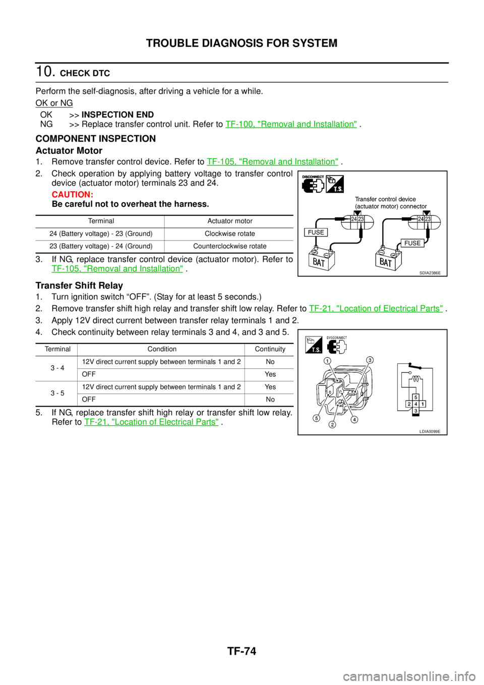
1. Remove transfer control device. Refer toTF-105, "Removal and Installation".
2. Check operation by applying battery voltage to transfer control
device (actuator motor) terminals 23 and 24.
CAUTION:
Be careful not to overheat the harness.
3. If NG, replace transfer control device (actuator motor). Refer to
TF-105, "
Removal and Installation".
Transfer Shift Relay
1. Turn ignition switch “OFF”. (Stay for at least 5 seconds.)
2. Remove transfer shift high relay and transfer shift low relay. Refer toTF-21, "
Location of Electrical Parts".
3. Apply 12V direct current between transfer relay terminals 1 and 2.
4. Check continuity between relay terminals 3 and 4, and 3 and 5.
5. If NG, replace transfer shift high relay or transfer shift low relay.
Refer toTF-21, "
Location of Electrical Parts".
Terminal Actuator motor
24 (Battery voltage) - 23 (Ground) Clockwise rotate
23 (Battery voltage) - 24 (Ground) Counterclockwise rotate
SDIA2386E
Terminal Condition Continuity
3-412V direct current supply between terminals 1 and 2 No
OFF Yes
3-512V direct current supply between terminals 1 and 2 Yes
OFF No
LDIA0099E
Page 3072 of 3171
TRANSFER CONTROL DEVICE
TF-105
C
E
F
G
H
I
J
K
L
MA
B
TF
TRANSFER CONTROL DEVICEPFP:33251
Removal and InstallationEDS0032M
REMOVAL
1. Switchthe4WDshiftswitchto2WDandsetthetransferassemblyto2WD.
2. Disconnect the transfer control device connector.
3. Remove the breather hose from the transfer control device.
4. Remove the bolts and detach the transfer control device.
INSTALLATION
1. Install the O-ring to the transfer control device.
CAUTION:
lDo not reuse O-ring.
lApply petroleum jelly to O-ring.
2. Install the transfer control device.
a. Turn the control shift rod fully counterclockwise using a flat-
bladed screwdriver, and then put a mark on the control shift rod.
b. Align the transfer control device shaft cutout with the mark on
the control shift rod, and install.
NOTE:
Turn the transfer control device when the transfer control device
connection does not match.
LDIA0136E
SDIA3378E
PDIA0119E
PDIA0120E
Page 3089 of 3171
TF-122
TRANSFER ASSEMBLY
7. Install the planetary carrier assembly and sun gear assembly to
the front case, using Tool.
8. Install the snap ring to the sun gear.
CAUTION:
lDo not reuse snap ring.
lDo not damage sun gear.
9. Set the L-H sleeve together with the L-H shift fork assembly onto
the planetary carrier assembly.
10. Install the control shift rod assembly to the front case.
CAUTION:
Set pin of L-H shift fork assembly into the groove of drum
cam.
11. Turn the control shift rod assembly fully counterclockwise.
12. Install the L-H shift rod assembly through the L-H shift fork
assembly opening to the front case.
CAUTION:
Set pin of L-H shift rod assembly into the groove of drum
cam.
13. Install the mainshaft to the sun gear assembly.Tool number : KV38100200
SDIA2791E
PDIA0099E
SDIA2438E
WDIA0215E
WDIA0216E
Page 3094 of 3171
TRANSFER ASSEMBLY
TF-127
C
E
F
G
H
I
J
K
L
MA
B
TF
38. Install the front oil seal until it is flush with the end face of the
front case, using Tool.
CAUTION:
lDo not reuse oil seal.
lApply petroleum jelly to oil seal.
39. Align the matching mark on the front drive shaft with the mark on
the companion flange, then install the companion flange.
40. Install the companion flange self-lock nut. Tighten to the speci-
fied torque, using Tool. Refer toTF-112, "
COMPONENTS".
CAUTION:
Do not reuse self-lock nut.
41. Install the O-ring to the transfer control device.
CAUTION:
lDo not reuse O-ring.
lApply petroleum jelly to O-ring.
42. Install the transfer control device to the rear case.
a. Turn the control shift rod fully counterclockwise using a flat-
bladed screwdriver, and then put a mark on the control shift rod.Tool number : KV38100500
PDIA0117E
SDIA2779E
Tool number : KV40104000
WDIA0219E
SDIA3378E
PDIA0119E