2005 NISSAN NAVARA bluetooth
[x] Cancel search: bluetoothPage 489 of 3171

AV-1
AUDIO-VISUAL SYSTEM
K ELECTRICAL
CONTENTS
C
D
E
F
G
H
I
J
L
M
SECTIONAV
A
B
AV
AUDIO-VISUAL SYSTEM
PRECAUTIONS .......................................................... 3
Precautions for Supplemental Restraint System
(SRS)“AIRBAG”and“SEATBELTPRE-TEN-
SIONER” .................................................................. 3
Wiring Diagrams and Trouble Diagnosis .................. 3
SYSTEM DESCRIPTION ............................................ 4
System Functions ..................................................... 4
AUDIO ................................................................... 4
NATS AUDIO LINK (WITHOUT NAVIGATION
SYSTEM) .............................................................. 4
VEHICLE INFORMATION SYSTEM ..................... 5
NAVIGATION SYSTEM ......................................... 5
HANDS-FREE PHONE ......................................... 7
Component Description ............................................ 8
AUDIO UNIT ......................................................... 8
NAVI CONTROL UNIT .......................................... 8
GPS ANTENNA .................................................... 9
DISPLAY UNIT ...................................................... 9
AV SWITCH .......................................................... 9
Component Parts Location ..................................... 10
Location Of Antenna .............................................. 10
Schematic — AUDIO — / With 1CD Player Type... 12
Wiring Diagram — AUDIO — / With 1CD Player Type
... 13
Schematic — AUDIO — / With 6CD Player Type... 16
Wiring Diagram — AUDIO — / With 6CD Player Type
... 17
Schematic — NAVI — ............................................ 20
Wiring Diagram — NAVI — .................................... 21
Schematic — NAVI — / COMM .............................. 28
Wiring Diagram — NAVI — / COMM ...................... 29
Wiring Diagram — TELEPHONE (PRE WIRE) —
/ Without NAVI ........................................................ 32
CAN Communication .............................................. 33
SYSTEM DESCRIPTION .................................... 33
TERMINALS AND REFERENCE VALUE FOR CON-
TROL UNIT ............................................................... 34
Audio Unit (1CD Player Type) ................................ 34
Audio Unit (6CD Player Type) Without NAVI .......... 35Audio Unit (With NAVI) ........................................... 37
NAVI Control Unit ................................................... 38
Display Unit ............................................................ 41
DIAGNOSIS SYSTEM ............................................... 44
Navigation System Diagnosis Function .................. 44
On Bord Self-Diagnosis Function ........................... 44
DESCRIPTION .................................................... 44
DIAGNOSIS ITEM ............................................... 44
OPERATION PROCEDURE ................................ 45
Self Diagnosis Mode ............................................... 46
ERROR DETECTION RANGE OF SELF-DIAG-
NOSIS MODE ..................................................... 47
DIAGNOSIS RESULTS ....................................... 47
Confirmation/Adjustment Mode .............................. 48
SCREEN TROUBLE DIAGNOSIS ...................... 49
VEHICLE SIGNALS ............................................ 49
SPEAKER TEST ................................................. 50
NAVIGATION ....................................................... 50
ERROR HISTORY ............................................... 51
VEHICLE CAN DIAGNOSIS ............................... 53
AV COMM DIAGNOSIS ....................................... 54
HANDSFREE PHONE ........................................ 54
BLUETOOTH ....................................................... 54
DELETE UNIT CONNECTION LOG ................... 55
CONSULT-II Functions ........................................... 56
CONSULT-II FUNCTIONS ................................... 56
CONSULT-II BASIC OPERATION PROCEDURE
... 56
SELF-DIAG RESULTS ........................................ 56
DATA MONITOR ................................................. 58
AV COMM MONITOR .......................................... 59
ECU PART NUMBER .......................................... 60
TROUBLE DIAGNOSIS ............................................ 61
Navigation System .................................................. 61
RGB Image ............................................................. 61
Voice Activated Control System ............................. 62
Steering Wheel Switch ............................................ 63
Component Parts Inspection .................................. 63
STEERING WHEEL SWITCH UNIT INSPEC-
Page 495 of 3171

SYSTEM DESCRIPTION
AV-7
C
D
E
F
G
H
I
J
L
MA
B
AV
GPS (Global Positioning System)
GPS (Global Positioning System) was developed for and is con-
trolled by the US Department of Defense. The system utilizes GPS
satellites (NAVSTAR), sending out radio waves while flying on an
orbit around the earth at an altitude of approximately 21,000 km
(13,000 miles).
The GPS receiver calculates the vehicle's position in three dimen-
sions (latitude/longitude/altitude) according to the time lag of the
radio waves received from four or more GPS satellites (three-dimen-
sional positioning). If radio waves were received only from three
GPS satellites, the GPS receiver calculates the vehicle's position in
two dimensions (latitude/longitude), utilizing the altitude data calcu-
lated previously with radio waves from four or more GPS satellites
(two-dimensional positioning).
Position correction by GPS is not available while the vehicle is stopped.
Accuracy of GPS will deteriorate under the following conditions:
lIn two-dimensional positioning, GPS accuracy will deteriorate when altitude of the vehicle position
changes.
lThe accuracy can be even lower depending on the arrangement of the GPS satellites utilized for the posi-
tioning.
lPosition detection is not possible when vehicle is in an area where radio waves from the GPS satellite do
not reach, such as in a tunnel, parking lot in a building, and under an elevated highway. Radio waves from
the GPS satellites may not be received when some object is located over the GPS antenna.
NOTE:
lEven a high-precision three dimensional positioning, the detection result has an error about 10 m (33 ft).
lBecause the signals of GPS satellite is controlled by the Tracking and Control Center in the United States,
the accuracy may be degraded lower intentionally or the radio waves may stop.
Traffic Information (RDS-TMC)
NOTE:This system is built-in NAVI control unit.
The Traffic Information broadcast allows to you to avoid delays due to traffic incidents.
Traffic jams, roadwork, closed roads around your current location, etc. are represented graphically on the map
by icons depicting the nature of the event.
Incidents on the route are automatically brought to your attention when they are approached.
The Traffic Information feature gives you the opportunity to forecast traffic incidents, determine how serious
they are and, via the guidance mode, allows you to detour around traffic incidents.
The navigation system receives traffic information from best available sources and enables the RDS-TMC
(Radio Data System-Traffic Information Channel) to inform and guide you.
The RDS-TMC broadcast is fed by a dedicated FM tuner so that you can still tune your radio station while Traf-
fic Information is being broadcasted.
HANDS-FREE PHONE
lNAVI control unit has Bluetooth module. It can perform wireless hands-free telephone calls using a cellu-
lar phone in vehicle compartment.
l5 or more portable phones can be registered into the NAVI control unit.
SEL526V
Page 532 of 3171

AV-44
DIAGNOSIS SYSTEM
DIAGNOSIS SYSTEM
PFP:00000
Navigation System Diagnosis FunctionEKS00Q6H
lThere are 2 diagnosis functions (on board diagnosis and diagnosis using CONSULT-II), and it is neces-
sary to use them properly according to the condition. If the on board diagnosis starts, perform diagnosis
with on board diagnosis. If the on board diagnosis does not start (the cause being that the system is not
started, the switch operation is not activated, etc.), perform diagnosis using CONSULT-II.
lAt on board diagnosis, the NAVI control unit diagnosis function starts by switch operation and the NAVI
control unit performs the diagnosis for each unit of system.
lAt diagnosis using CONSULT-II, the NAVI control unit diagnosis function starts by the communication
between CONSULT-II and NAVI control unit, and the NAVI control unit performs the diagnosis for each
unit of system.
On Bord Self-Diagnosis FunctionEKS00Q6I
DESCRIPTION
lThe on board diagnosis function has a self-diagnosis mode for performing trouble diagnosis automatically
and a Confirmation/Adjustment mode for operating manually.
lSelf-diagnosis mode performs the diagnosis at NAVI control unit, connections between each unit that
composes the system, and connections between NAVI control unit and GPS antenna. It displays the
results on the display.
lConfirmation/Adjustment mode is used to monitor the vehicle signals requiring operation and judgement
by a technician (malfunctions that cannot be automatically judged by the system), the confirmation/adjust-
ment of setting value, the error history of system, and the communication condition of system.
DIAGNOSIS ITEM
Mode Description
Self Diagnosis
lNAVI control unit diagnosis (DVD-ROM drive will not be diagnosed when
no map DVD-ROM is in it.)
lThe connection diagnosis between NAVI control unit and GPS antenna
and the connection diagnosis between NAVI control unit and each unit
can be performed.
Confirma-
tion/Adjust-
mentDisplay DiagnosisThe tint can be confirmed by the color spectrum bar display. The shading
of color can be confirmed by the gradation bar display.
Vehicle SignalsDiagnosis of signals can be performed for vehicle speed, parking brake,
lights, ignition (ignition switch), and reverse.
Speaker Test The connection of a speaker can be confirmed by test tone.
NavigationSteering Angle
AdjustmentWhen there is a difference between the actual turning angle and the vehi-
cle mark turning angle, it can be adjusted.
Speed CalibrationWhen there is a difference between the current location mark and the
actual location, it can be adjusted.
Error HistoryThe system malfunction and its frequency that occurred in the past are dis-
played. When the malfunctioning item is selected, the time and place that
the selected malfunction last occurred are displayed.
Vehicle CAN Diagnosis The transmitting/receiving of CAN communication can be monitored.
AV COMM DiagnosisThe communication condition of each unit that composes the system can
be monitored.
Handsfree PhoneEach setting of hands-free volume adjustment, voice microphone test,
delete hands-free memory can be performed.
Bluetooth Passkey and device name can be confirmed/changed.
Delete Unit Commection Log The connection history and error history of unit can be deleted.
Page 541 of 3171

DIAGNOSIS SYSTEM
AV-53
C
D
E
F
G
H
I
J
L
MA
B
AV
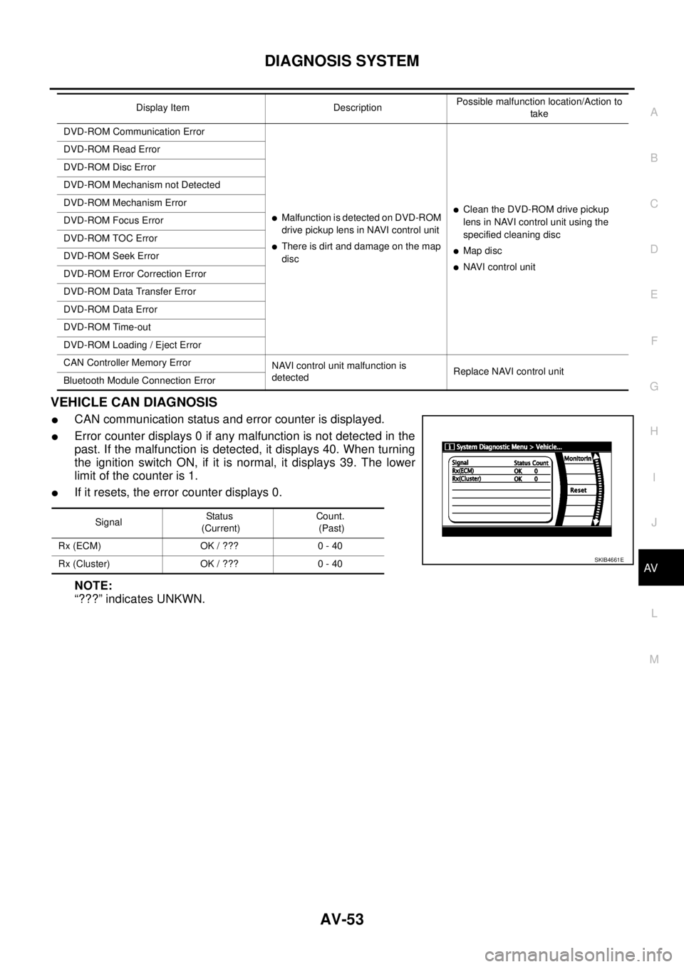
VEHICLE CAN DIAGNOSIS
lCAN communication status and error counter is displayed.
lError counter displays 0 if any malfunction is not detected in the
past. If the malfunction is detected, it displays 40. When turning
the ignition switch ON, if it is normal, it displays 39. The lower
limitofthecounteris1.
lIf it resets, the error counter displays 0.
NOTE:
“???” indicates UNKWN.
DVD-ROM Communication Error
lMalfunction is detected on DVD-ROM
drive pickup lens in NAVI control unit
lThere is dirt and damage on the map
disc
lClean the DVD-ROM drive pickup
lens in NAVI control unit using the
specified cleaning disc
lMap disc
lNAVI control unit DVD-ROM Read Error
DVD-ROM Disc Error
DVD-ROM Mechanism not Detected
DVD-ROM Mechanism Error
DVD-ROM Focus Error
DVD-ROM TOC Error
DVD-ROM Seek Error
DVD-ROM Error Correction Error
DVD-ROM Data Transfer Error
DVD-ROM Data Error
DVD-ROM Time-out
DVD-ROM Loading / Eject Error
CAN Controller Memory Error
NAVI control unit malfunction is
detectedReplace NAVI control unit
Bluetooth Module Connection ErrorDisplay Item DescriptionPossible malfunction location/Action to
take
SignalStatu s
(Current)Count.
(Past)
Rx (ECM) OK / ??? 0 - 40
Rx (Cluster) OK / ??? 0 - 40
SKIB4661E
Page 542 of 3171

AV-54
DIAGNOSIS SYSTEM
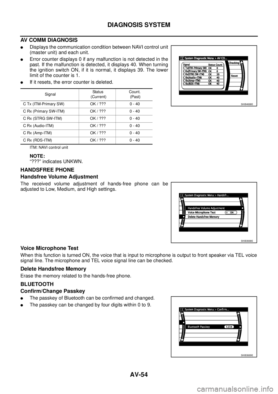
AV COMM DIAGNOSIS
lDisplays the communication condition between NAVI control unit
(master unit) and each unit.
lError counter displays 0 if any malfunction is not detected in the
past. If the malfunction is detected, it displays 40. When turning
the ignition switch ON, if it is normal, it displays 39. The lower
limitofthecounteris1.
lIf it resets, the error counter is deleted.
ITM: NAVI control unit
NOTE:
“???” indicates UNKWN.
HANDSFREE PHONE
Handsfree Volume Adjustment
The received volume adjustment of hands-free phone can be
adjusted to Low, Medium, and High settings.
Voice Microphone Test
When this function is turned ON, the voice that is input to microphone is output to front speaker via TEL voice
signal line. The microphone and TEL voice signal line can be checked.
Delete Handsfree Memory
Erase the memory related to the hands-free phone.
BLUETOOTH
Confirm/Change Passkey
lThe passkey of Bluetooth can be confirmed and changed.
lThe passkey can be changed by four digits within 0 to 9.
SignalStatus
(Current)Count.
(Past)
C Tx (ITM-Primary SW) OK / ??? 0 - 40
CRx(PrimarySW-ITM) OK/??? 0-40
C Rx (STRG SW-ITM) OK / ??? 0 - 40
C Rx (Audio-ITM) OK / ??? 0 - 40
C Rx (Amp-ITM) OK / ??? 0 - 40
C Rx (RDS-ITM) OK / ??? 0 - 40
SKIB4668E
SKIB3668E
SKIB3669E
Page 543 of 3171

DIAGNOSIS SYSTEM
AV-55
C
D
E
F
G
H
I
J
L
MA
B
AV
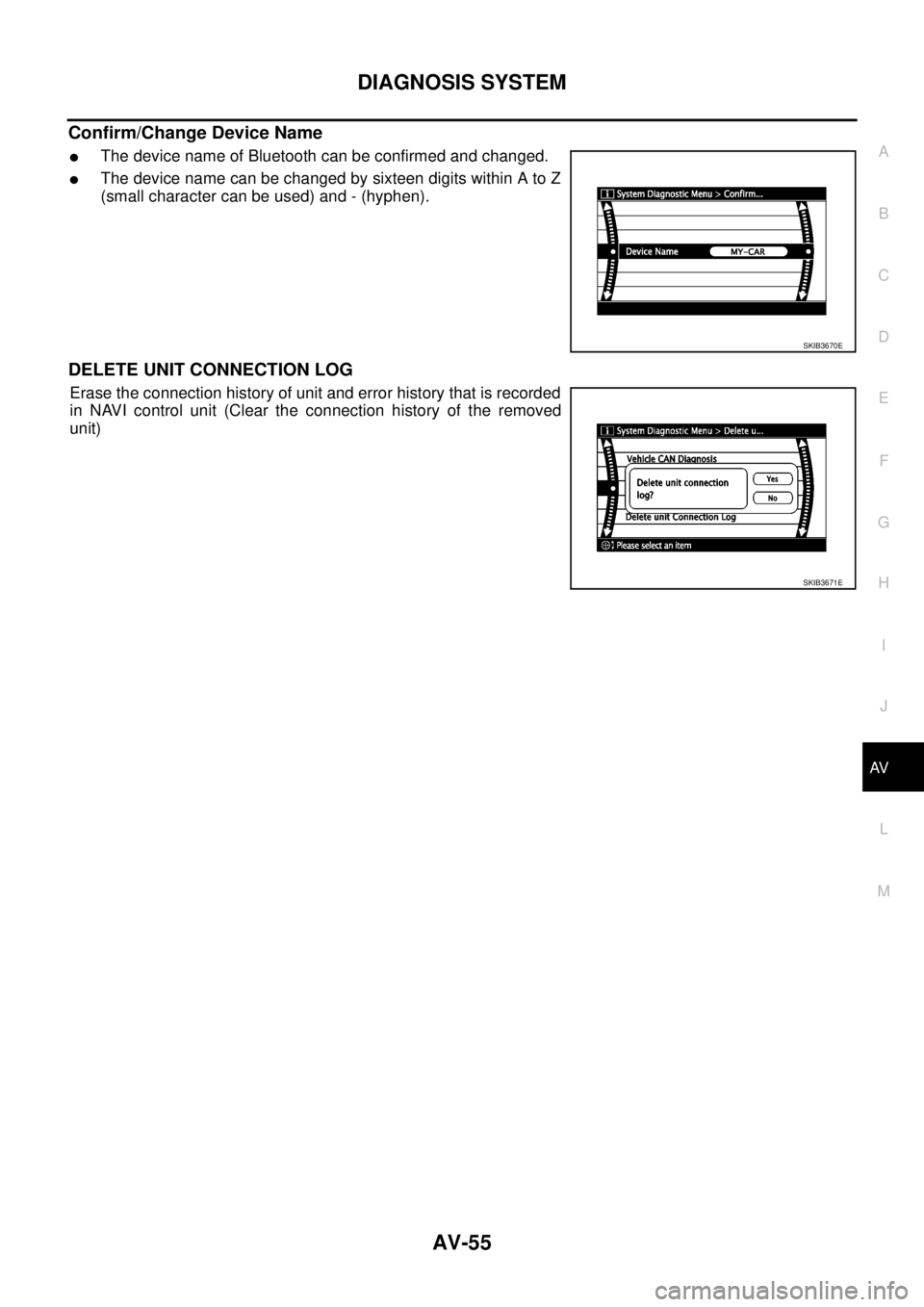
Confirm/Change Device Name
lThe device name of Bluetooth can be confirmed and changed.
lThe device name can be changed by sixteen digits within A to Z
(small character can be used) and - (hyphen).
DELETE UNIT CONNECTION LOG
Erase the connection history of unit and error history that is recorded
in NAVI control unit (Clear the connection history of the removed
unit)
SKIB3670E
SKIB3671E
Page 546 of 3171

AV-58
DIAGNOSIS SYSTEM
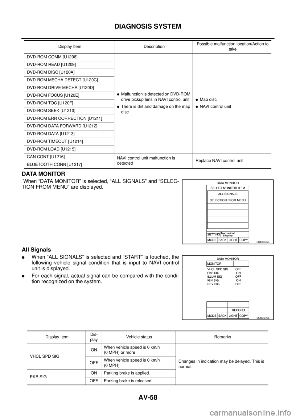
DATA MONITOR
When “DATA MONITOR” is selected, “ALL SIGNALS” and “SELEC-
TION FROM MENU” are displayed.
All Signals
lWhen “ALL SIGNALS” is selected and “START” is touched, the
following vehicle signal condition that is input to NAVI control
unit is displayed.
lFor each signal, actual signal can be compared with the condi-
tion recognized on the system.
DVD-ROM COMM [U1208]
lMalfunctionisdetectedonDVD-ROM
drive pickup lens in NAVI control unit
lThere is dirt and damage on the map
disc
lMap disc
lNAVI control unit DVD-ROM READ [U1209]
DVD-ROM DISC [U120A]
DVD-ROM MECHA DETECT [U120C]
DVD-ROM DRIVE MECHA [U120D]
DVD-ROM FOCUS [U120E]
DVD-ROM TOC [U120F]
DVD-ROM SEEK [U1210]
DVD-ROM ERR CORRECTION [U1211]
DVD-ROM DATA FORWARD [U1212]
DVD-ROM DATA [U1213]
DVD-ROM TIMEOUT [U1214]
DVD-ROM LOAD [U1215]
CAN CONT [U1216]
NAVI control unit malfunction is
detectedReplace NAVI control unit
BLUETOOTH CONN [U1217]Display Item DescriptionPossible malfunction location/Action to
take
SKIB3675E
SKIB3676E
Display ItemDis-
playVehicle status Remarks
VHCL SPD SIGONWhen vehicle speed is 0 km/h
(0 MPH) or more
Changes in indication may be delayed. This is
normal. OFFWhen vehicle speed is 0 km/h
(0 MPH)
PKB SIGON Parking brake is applied.
OFF Parking brake is released.