2005 NISSAN NAVARA service indicator
[x] Cancel search: service indicatorPage 11 of 3171

AT-3
D
E
F
G
H
I
J
K
L
MA
B
AT CONSULT-II Reference Value .............................. 144
On Board Diagnosis Logic ................................... 144
Possible Cause .................................................... 144
DTC Confirmation Procedure ............................... 144
Diagnostic Procedure ........................................... 145
DTC P1767 HIGH AND LOW REVERSE CLUTCH
SOLENOID VALVE ................................................. 147
Description ........................................................... 147
CONSULT-II Reference Value .............................. 147
On Board Diagnosis Logic ................................... 147
Possible Cause .................................................... 147
DTC Confirmation Procedure ............................... 147
Diagnostic Procedure ........................................... 148
DTC P1769 HIGH AND LOW REVERSE CLUTCH
SOLENOID VALVE FUNCTION ............................. 149
Description ........................................................... 149
CONSULT-II Reference Value .............................. 149
On Board Diagnosis Logic ................................... 149
Possible Cause .................................................... 149
DTC Confirmation Procedure ............................... 149
Diagnostic Procedure ........................................... 150
DTC P1772 LOW COAST BRAKE SOLENOID
VALVE ..................................................................... 152
Description ........................................................... 152
CONSULT-II Reference Value .............................. 152
On Board Diagnosis Logic ................................... 152
Possible Cause .................................................... 152
DTC Confirmation Procedure ............................... 152
Diagnostic Procedure ........................................... 153
DTC P1774 LOW COAST BRAKE SOLENOID
VALVE FUNCTION ................................................. 154
Description ........................................................... 154
CONSULT-II Reference Value .............................. 154
On Board Diagnosis Logic ................................... 154
Possible Cause .................................................... 154
DTC Confirmation Procedure ............................... 154
Diagnostic Procedure ........................................... 155
DTC P1841 ATF PRESSURE SWITCH 1 ............... 156
Description ........................................................... 156
CONSULT-II Reference Value .............................. 156
On Board Diagnosis Logic ................................... 156
Possible Cause .................................................... 156
DTC Confirmation Procedure ............................... 156
Diagnostic Procedure ........................................... 157
DTC P1843 ATF PRESSURE SWITCH 3 ............... 158
Description ........................................................... 158
CONSULT-II Reference Value .............................. 158
On Board Diagnosis Logic ................................... 158
Possible Cause .................................................... 158
DTC Confirmation Procedure ............................... 158
Diagnostic Procedure ........................................... 159
DTC P1845 ATF PRESSURE SWITCH 5 ............... 160
Description ........................................................... 160
CONSULT-II Reference Value .............................. 160
On Board Diagnosis Logic ................................... 160
Possible Cause .................................................... 160
DTC Confirmation Procedure ............................... 160
Diagnostic Procedure ........................................... 161
DTC P1846 ATF PRESSURE SWITCH 6 ............... 162Description ............................................................162
CONSULT-II Reference Value ..............................162
On Board Diagnosis Logic ....................................162
Possible Cause .....................................................162
DTC Confirmation Procedure ...............................162
Diagnostic Procedure ...........................................163
MAIN POWER SUPPLY AND GROUND CIRCUIT. 164
Wiring Diagram — AT — MAIN ............................164
Diagnostic Procedure ...........................................165
CLOSED THROTTLE POSITION AND WIDE OPEN
THROTTLE POSITION CIRCUIT ............................168
CONSULT-II Reference Value ..............................168
Diagnostic Procedure ...........................................168
BRAKE SIGNAL CIRCUIT ......................................169
CONSULT-II Reference Value ..............................169
Diagnostic Procedure ...........................................169
1ST POSITION SWITCH .........................................170
CONSULT-II Reference Value ..............................170
Diagnostic Procedure ...........................................170
OVERDRIVE CONTROL SWITCH .........................172
CONSULT-II Reference Value ..............................172
Diagnostic Procedure ...........................................172
TROUBLE DIAGNOSIS FOR SYMPTOMS ............174
Wiring Diagram — AT — NONDTC ......................174
OD OFF Indicator Lamp Does Not Come On .......177
Engine Cannot Be Started in “P” or “N” Position ..177
In “P” Position, Vehicle Moves When Pushed ......178
In “N” Position, Vehicle Moves ..............................179
Large Shock (“N” to “D” Position) .........................180
Vehicle Does Not Creep Backward in “R” Position. 182
Vehicle Does Not Creep Forward in “D” Position . 184
Vehicle Cannot Be Started from D
1......................186
A/T Does Not Shift: D
1®D2................................188
A/T Does Not Shift: D
2®D3................................190
A/T Does Not Shift: D
3®D4................................192
A/T Does Not Shift: D
4®D5................................194
A/T Does Not Perform Lock-up ............................196
A/T Does Not Hold Lock-up Condition ..................197
Lock-up Is Not Released ......................................199
Engine Speed Does Not Return to Idle ................199
A/T Does Not Shift: 5th Gear®4th Gear ............200
A/T Does Not Shift: 4th Gear®3rd Gear ............202
A/T Does Not Shift: 3rd Gear®2nd Gear ...........203
A/T Does Not Shift: 2nd Gear®1st Gear ...........204
Vehicle Does Not Decelerate by Engine Brake ....206
SHIFT CONTROL SYSTEM ....................................208
Control Device Removal and Installation ..............208
Control Cable Removal and Installation ...............210
Adjustment of A/T Position ...................................211
Checking of A/T Position ......................................211
A/T SHIFT LOCK SYSTEM ....................................212
Description ............................................................212
Shift Lock System Electrical Parts Location .........212
Wiring Diagram — A/T — SHIFT ..........................213
Diagnostic Procedure ...........................................214
KEY INTERLOCK CABLE ......................................216
Removal and Installation ......................................216
ON-VEHICLE SERVICE ..........................................218
Control Valve With TCM and A/T Fluid Temperature
Page 46 of 3171

AT-38
TROUBLE DIAGNOSIS
DIAGNOSTIC WORKSHEET
Information from Customer
KEY POINTS
lWHAT..... Vehicle & A/T model
lWHEN..... Date, Frequencies
lWHERE..... Road conditions
lHOW..... Operating conditions, Symptoms
Diagnostic Worksheet Chart
Customer name MR/MS Model & Year VIN
Trans. Model Engine Mileage
Malfunction Date Manuf. Date In Service Date
FrequencyoContinuousoIntermittent (times a day)
SymptomsoVehicle does not move. (oAny positionoParticular position)
oNo up-shift (o1st®2ndo2nd®3rdo3rd®4tho4th®5th)
oNo down-shift (o5th®4tho4th®3rdo3rd®2ndo2nd®1st)
oLock-up malfunction
oShift point too high or too low.
oShift shock or slip (oN®DoLock-upoAny drive position)
oNoise or vibration
oNo kick down
oNo pattern select
oOthers
()
OD OFF indicator lampoContinuously litoNot lit
1oRead the item on cautions concerning fail-safe and understand the customer's complaint.AT- 3 4
2oA/T fluid inspectionAT- 4 3oLeak (Repair leak location.)
oState
oAmount
3oStall test and line pressure testAT- 4 3
AT- 4 4oStall te st
oTorque converter one-way clutch
oFront brake
oHigh and low reverse clutch
oLow coast brake
oForward brake
oReverse brake
oForward one-way clutcho1st one-way clutch
o3rd one-way clutch
oEngine
oLine pressure low
oExcept for input clutch and direct
clutch, clutches and brakes OK
oLine pressure inspection - Suspected part:
Page 553 of 3171

TROUBLE DIAGNOSIS
AV-65
C
D
E
F
G
H
I
J
L
MA
B
AV
Example of Symptoms Not MalfunctionEKS00Q6T
BASIC OPERATION
NOTE:
Locations stored in the Address Book and other memory functions may be lost if the vehicle's battery is disconnected or becomes dis-
charged. If this occurs, service the vehicle's battery as necessary and re-enter the information in the Address Book.
VEHICLE ICON
Symptom Possible cause Possible solution
No image is displayed.The brightness is at the lowest setting. Adjust the brightness of the display.
The display is turned off.
Press and hold to turn on the display.
No voice guidance is available.
The volume is too high or too low.The volume is not set correctly, or it is turned off. Adjust the volume of voice guidance.
Volume guidance is not provided for narrow streets
(roads displayed in gray).This is not a malfunction.
No map is displayed on the screen.The map DVD-ROM is not inserted, or it is inserted
upside down.Insert the map DVD-ROM correctly.
A screen other than map screen is displayed. Press “MAP”.
Thescreenistoodim.
The movement is slow.The temperature in the interior of the vehicle is low.Wait until the interior of the vehicle has
warmed up.
Some pixels in the display are
darker or brighter than others.This condition is an inherent characteristic of liquid
crystal displays.This is not a malfunction.
Some menu items cannot be
selected.Some menu items become unavailable while the
vehicle is driven.Park the vehicle in a safe location, and
then operate the navigation system.
Symptom Possible cause Possible solution
Names of roads and locations dif-
fer between Plan view and Bird-
view™.This is because the quantity of the displayed infor-
mation is reduced so that the screen does not
become too crowded. There is also a chance that
names of the roads or locations may be displayed
multiple times, and the names appearing on the a
screen may be different because of a processing
procedure.This is not a malfunction.
The vehicle icon is not displayed in
the correct position.The vehicle was transported after the ignition switch
was turned off, for example, by a ferry or car trans-
porter.Drive the vehicle for a while on a road
whereGPScanbereceived.
The position and direction of the vehicle may be
incorrect depending on the driving environments and
the levels of positioning accuracy of the navigation
system.This is not a malfunction. Drive the vehi-
cle for a while to automatically correct the
position and direction of the vehicle icon.
Whenthevehicleistravellingona
new road, the vehicle icon is
located on another road nearby.Because the new road is not stored in the map data,
the system automatically places the vehicle ion on
the nearest road available.Updated road information will be included
in the next version of the map DVD-ROM.
The screen does not switch to the
night screen even after turning on
the headlights.The daytime screen was set the last time the head-
lights were turned on.Set the screen to the night screen mode
using when turning on the headlights.
The map does not scroll even
when the vehicle is moving.The current location map screen is not displayed. Press “MAP”.
The vehicle icon is not displayed. The current location map screen is not displayed. Press “MAP”.
The GPS indicator on the screen
remains gray.GPS signals cannot be received depending on the
vehicle location, such as in a parking garage, on a
road that has numerous tall buildings, etc.Drive on an open, straight road for a
while.
GPS signals cannot be received because objects
are placed on the rear parcel shelf.Remove the objects from the rear parcel
shelf.
A sufficient amount of GPS satellites are not avail-
able.Wait for the satellites to move locations
available for navigation system.
Page 621 of 3171

POWERDOORLOCKSYSTEM
BL-37
C
D
E
F
G
H
J
K
L
MA
B
BL
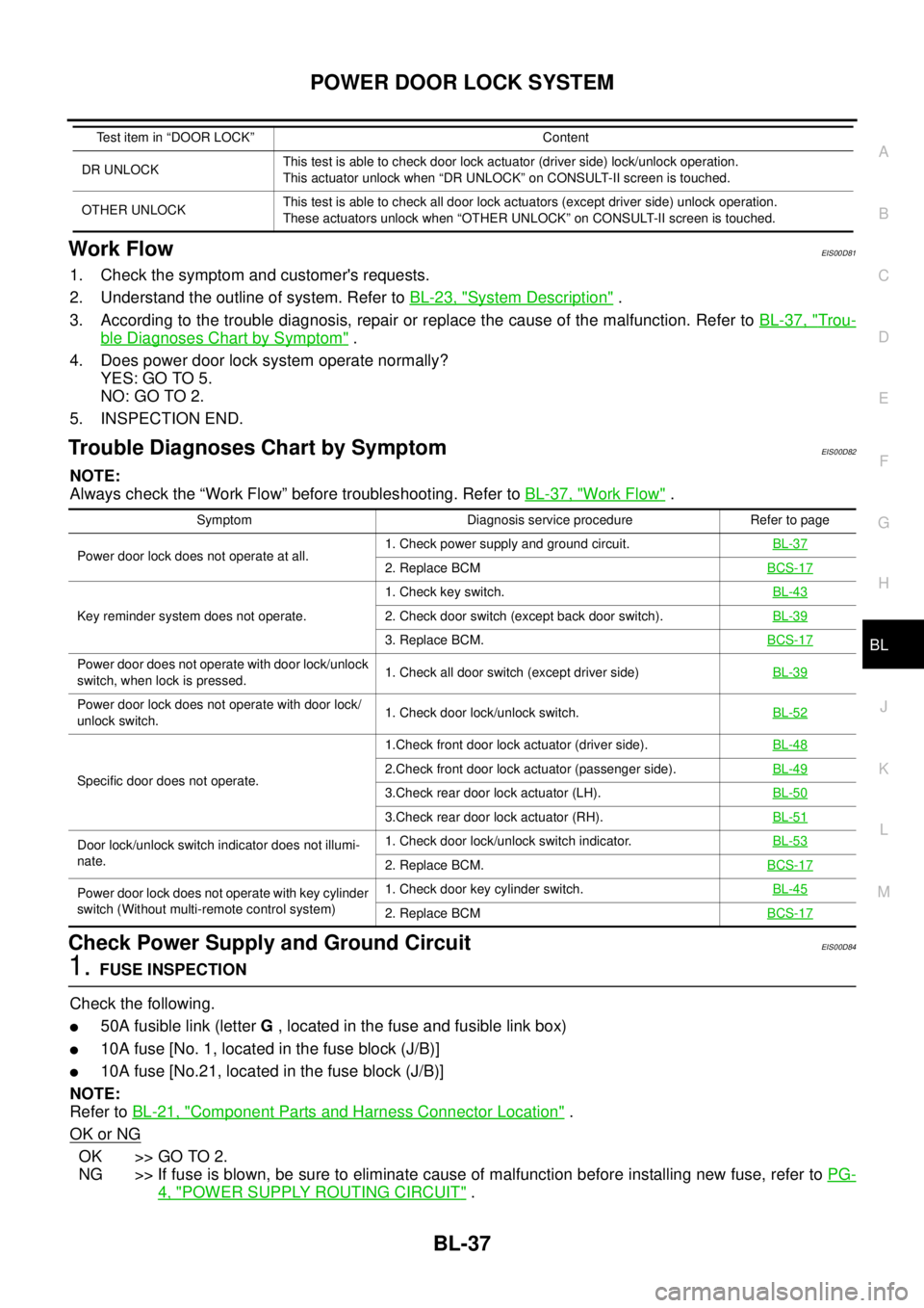
Work FlowEIS00D81
1. Check the symptom and customer's requests.
2. Understand the outline of system. Refer toBL-23, "
System Description".
3. According to the trouble diagnosis, repair or replace the cause of the malfunction. Refer toBL-37, "
Trou-
ble Diagnoses Chart by Symptom".
4. Does power door lock system operate normally?
YES: GO TO 5.
NO:GOTO2.
5. INSPECTION END.
Trouble Diagnoses Chart by SymptomEIS00D82
NOTE:
Always check the “Work Flow” before troubleshooting. Refer toBL-37, "
Work Flow".
Check Power Supply and Ground CircuitEIS00D84
1.FUSE INSPECTION
Check the following.
l50A fusible link (letterG, located in the fuse and fusible link box)
l10A fuse [No. 1, located in the fuse block (J/B)]
l10A fuse [No.21, located in the fuse block (J/B)]
NOTE:
Refer toBL-21, "
Component Parts and Harness Connector Location".
OK or NG
OK >> GO TO 2.
NG >> If fuse is blown, be sure to eliminate cause of malfunction before installing new fuse, refer toPG-
4, "POWER SUPPLY ROUTING CIRCUIT".
DR UNLOCKThis test is able to check door lock actuator (driver side) lock/unlock operation.
This actuator unlock when “DR UNLOCK” on CONSULT-II screen is touched.
OTHER UNLOCKThis test is able to check all door lock actuators (except driver side) unlock operation.
These actuators unlock when “OTHER UNLOCK” on CONSULT-II screen is touched. Test item in “DOOR LOCK” Content
Symptom Diagnosis service procedure Refer to page
Power door lock does not operate at all.1. Check power supply and ground circuit.BL-37
2. Replace BCMBCS-17
Key reminder system does not operate.1. Check key switch.BL-432. Check door switch (except back door switch).BL-39
3. Replace BCM.BCS-17
Power door does not operate with door lock/unlock
switch, when lock is pressed.1. Check all door switch (except driver side)BL-39
Power door lock does not operate with door lock/
unlock switch.1. Check door lock/unlock switch.BL-52
Specific door does not operate.1.Check front door lock actuator (driver side).BL-482.Check front door lock actuator (passenger side).BL-49
3.Check rear door lock actuator (LH).BL-50
3.Check rear door lock actuator (RH).BL-51
Door lock/unlock switch indicator does not illumi-
nate.1. Check door lock/unlock switch indicator.BL-53
2. Replace BCM.BCS-17
Power door lock does not operate with key cylinder
switch (Without multi-remote control system)1. Check door key cylinder switch.BL-45
2. Replace BCMBCS-17
Page 656 of 3171

BL-72
POWER DOOR LOCK — SUPER LOCK —
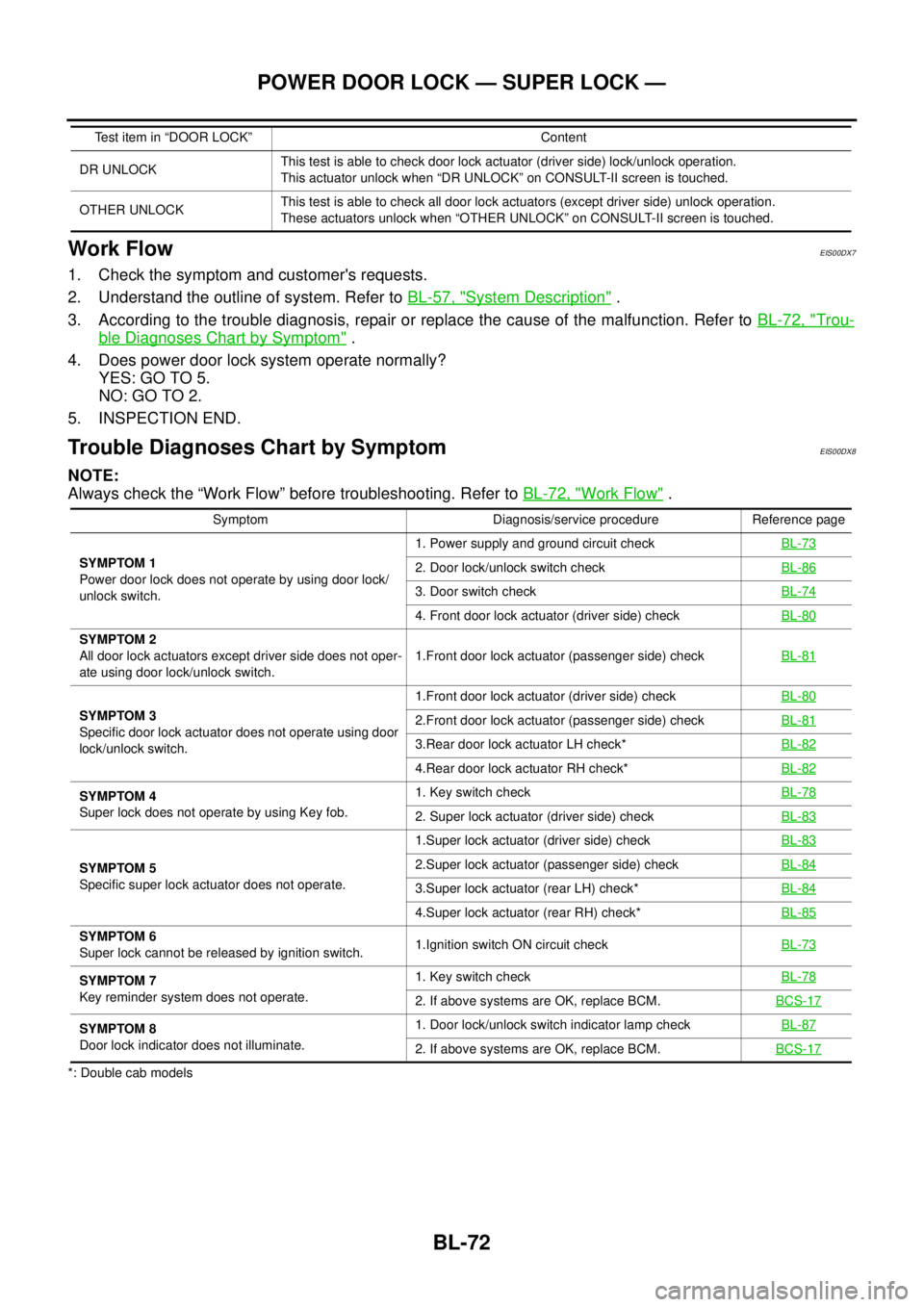
Work Flow
EIS00DX7
1. Check the symptom and customer's requests.
2. Understand the outline of system. Refer toBL-57, "
System Description".
3. According to the trouble diagnosis, repair or replace the cause of the malfunction. Refer toBL-72, "
Trou-
ble Diagnoses Chart by Symptom".
4. Does power door lock system operate normally?
YES: GO TO 5.
NO:GOTO2.
5. INSPECTION END.
Trouble Diagnoses Chart by SymptomEIS00DX8
NOTE:
Always check the “Work Flow” before troubleshooting. Refer toBL-72, "
Work Flow".
*: Double cab modelsDR UNLOCKThis test is able to check door lock actuator (driver side) lock/unlock operation.
This actuator unlock when “DR UNLOCK” on CONSULT-II screen is touched.
OTHER UNLOCKThis test is able to check all door lock actuators (except driver side) unlock operation.
These actuators unlock when “OTHER UNLOCK” on CONSULT-II screen is touched. Test item in “DOOR LOCK” Content
Symptom Diagnosis/service procedure Reference page
SYMPTOM 1
Power door lock does not operate by using door lock/
unlock switch.1. Power supply and ground circuit checkBL-73
2. Door lock/unlock switch checkBL-86
3. Door switch checkBL-74
4. Front door lock actuator (driver side) checkBL-80
SYMPTOM 2
All door lock actuators except driver side does not oper-
ate using door lock/unlock switch.1.Front door lock actuator (passenger side) checkBL-81
SYMPTOM 3
Specific door lock actuator does not operate using door
lock/unlock switch.1.Front door lock actuator (driver side) checkBL-802.Front door lock actuator (passenger side) checkBL-81
3.Rear door lock actuator LH check*BL-82
4.Rear door lock actuator RH check*BL-82
SYMPTOM 4
Super lock does not operate by using Key fob.1. Key switch checkBL-78
2. Super lock actuator (driver side) checkBL-83
SYMPTOM 5
Specific super lock actuator does not operate.1.Super lock actuator (driver side) checkBL-832.Super lock actuator (passenger side) checkBL-84
3.Super lock actuator (rear LH) check*BL-84
4.Super lock actuator (rear RH) check*BL-85
SYMPTOM 6
Super lock cannot be released by ignition switch.1.Ignition switch ON circuit checkBL-73
SYMPTOM 7
Key reminder system does not operate.1. Key switch checkBL-78
2. If above systems are OK, replace BCM.BCS-17
SYMPTOM 8
Door lock indicator does not illuminate.1. Door lock/unlock switch indicator lamp checkBL-87
2. If above systems are OK, replace BCM.BCS-17
Page 923 of 3171

COMBINATION METERS
DI-13
C
D
E
F
G
H
I
J
L
MA
B
DI
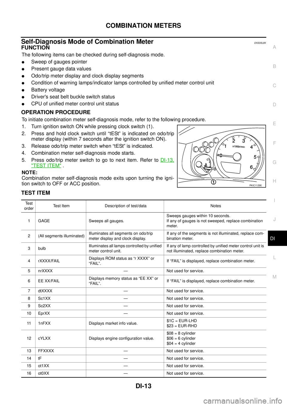
Self-Diagnosis Mode of Combination MeterEKS00L8K
FUNCTION
The following items can be checked during self-diagnosis mode.
lSweep of gauges pointer
lPresent gauge data values
lOdo/trip meter display and clock display segments
lCondition of warning lamps/indicator lamps controlled by unified meter control unit
lBattery voltage
lDriver's seat belt buckle switch status
lCPU of unified meter control unit status
OPERATION PROCEDURE
To initiate combination meter self-diagnosis mode, refer to the following procedure.
1. Turn ignition switch ON while pressing clock switch (1).
2. Press and hold clock switch until “tESt” is indicated on odo/trip
meter display (within 7 seconds after the ignition switch ON).
3. Release odo/trip meter switch when “tESt” is indicated.
4. Combination meter self-diagnosis mode starts.
5. Pressodo/tripmeterswitchtogotonextitem.RefertoDI-13,
"TEST ITEM".
NOTE:
Combination meter self-diagnosis mode exits upon turning the igni-
tion switch to OFF or ACC position.
TEST ITEM
PKIC1129E
Te s t
orderTest Item Description of test/data Notes
1 GAGE Sweeps all gauges.Sweeps gauges within 10 seconds.
If any of gauges is not sweeped, replace combination
meter.
2 (All segments illuminated)Illuminates all segments on odo/trip
meter display and clock display.If any of the segments is not illuminated, replace com-
bination meter.
3 bulbIlluminates all lamps controlled by unified
meter control unit.If any of lamp controlled by unified meter control unit is
not illuminated, replace combination meter.
4 rXXXX/FAILDisplays ROM status as “r XXXX” or
“FAIL”.If “FAIL” is displayed, replace combination meter.
5 nrXXXX — Not used for service.
6 EE XX/FAILDisplays memory status as “EE XX” or
“FAIL”.If “FAIL” is displayed, replace combination meter.
7 dtXXXX — Not used for service.
8 Sc1XX — Not used for service.
9 Sc2XX — Not used for service.
10 EprXX — Not used for service.
11 1nFXX Displays market info value.$1C = EUR-LHD
$23 = EUR-RHD
12 cYLXX Displays engine configuration value.$08 = 8 cylinder
$06 = 6 cylinder
$04 = 4 cylinder
13 FFXXXX — Not used for service.
14 tF — Not used for service.
15 ot1XX — Not used for service.
16 ot0XX — Not used for service.
Page 981 of 3171

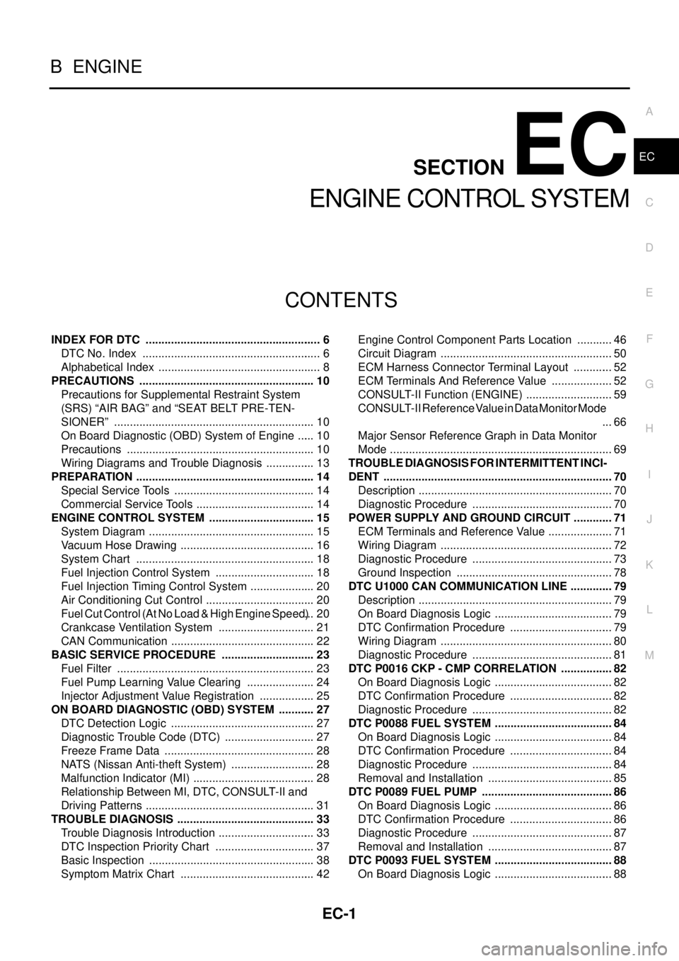
EC-1
ENGINE CONTROL SYSTEM
B ENGINE
CONTENTS
C
D
E
F
G
H
I
J
K
L
M
SECTIONEC
A
EC
ENGINE CONTROL SYSTEM
INDEX FOR DTC ........................................................ 6
DTC No. Index ......................................................... 6
Alphabetical Index .................................................... 8
PRECAUTIONS ........................................................ 10
Precautions for Supplemental Restraint System
(SRS)“AIRBAG”and“SEATBELTPRE-TEN-
SIONER” ................................................................ 10
On Board Diagnostic (OBD) System of Engine ...... 10
Precautions ............................................................ 10
Wiring Diagrams and Trouble Diagnosis ................ 13
PREPARATION ......................................................... 14
Special Service Tools ............................................. 14
Commercial Service Tools ...................................... 14
ENGINE CONTROL SYSTEM .................................. 15
System Diagram ..................................................... 15
Vacuum Hose Drawing ........................................... 16
System Chart ......................................................... 18
Fuel Injection Control System ................................ 18
Fuel Injection Timing Control System ..................... 20
Air Conditioning Cut Control ................................... 20
Fuel Cut Control (At No Load & High Engine Speed)... 20
Crankcase Ventilation System ............................... 21
CAN Communication .............................................. 22
BASIC SERVICE PROCEDURE .............................. 23
Fuel Filter ............................................................... 23
Fuel Pump Learning Value Clearing ...................... 24
Injector Adjustment Value Registration .................. 25
ON BOARD DIAGNOSTIC (OBD) SYSTEM ............ 27
DTC Detection Logic .............................................. 27
Diagnostic Trouble Code (DTC) ............................. 27
Freeze Frame Data ................................................ 28
NATS (Nissan Anti-theft System) ........................... 28
Malfunction Indicator (MI) ....................................... 28
Relationship Between MI, DTC, CONSULT-II and
Driving Patterns ...................................................... 31
TROUBLE DIAGNOSIS ............................................ 33
Trouble Diagnosis Introduction ............................... 33
DTC Inspection Priority Chart ................................ 37
Basic Inspection ..................................................... 38
Symptom Matrix Chart ........................................... 42Engine Control Component Parts Location ............ 46
Circuit Diagram ....................................................... 50
ECM Harness Connector Terminal Layout ............. 52
ECM Terminals And Reference Value .................... 52
CONSULT-II Function (ENGINE) ............................ 59
CONSULT-II Reference Value in Data Monitor Mode
... 66
Major Sensor Reference Graph in Data Monitor
Mode ....................................................................... 69
TROUBLE DIAGNOSIS FOR INTERMITTENT INCI-
DENT ......................................................................... 70
Description .............................................................. 70
Diagnostic Procedure ............................................. 70
POWER SUPPLY AND GROUND CIRCUIT ............. 71
ECM Terminals and Reference Value ..................... 71
Wiring Diagram ....................................................... 72
Diagnostic Procedure ............................................. 73
Ground Inspection .................................................. 78
DTC U1000 CAN COMMUNICATION LINE .............. 79
Description .............................................................. 79
On Board Diagnosis Logic ...................................... 79
DTC Confirmation Procedure ................................. 79
Wiring Diagram ....................................................... 80
Diagnostic Procedure ............................................. 81
DTC P0016 CKP - CMP CORRELATION ................. 82
On Board Diagnosis Logic ...................................... 82
DTC Confirmation Procedure ................................. 82
Diagnostic Procedure ............................................. 82
DTC P0088 FUEL SYSTEM ...................................... 84
On Board Diagnosis Logic ...................................... 84
DTC Confirmation Procedure ................................. 84
Diagnostic Procedure ............................................. 84
Removal and Installation ........................................ 85
DTC P0089 FUEL PUMP .......................................... 86
On Board Diagnosis Logic ...................................... 86
DTC Confirmation Procedure ................................. 86
Diagnostic Procedure ............................................. 87
Removal and Installation ........................................ 87
DTC P0093 FUEL SYSTEM ...................................... 88
On Board Diagnosis Logic ...................................... 88
Page 985 of 3171

EC-5
C
D
E
F
G
H
I
J
K
L
M
ECA . 303
ECM Terminals and Reference Value .................. 303
Wiring Diagram .................................................... 304
Diagnostic Procedure ........................................... 305
Component Inspection ......................................... 307
Removal and Installation ...................................... 308
TC BOOST CONTROL SOLENOID VALVE ........... 309
Description ........................................................... 309
ECM Terminals and Reference Value .................. 310
Wiring Diagram ..................................................... 311
Diagnostic Procedure ........................................... 312
Component Inspection ......................................... 313
Removal and Installation ...................................... 313
INTAKE AIR CONTROL VALVE CONTROL SOLE-
NOID VALVE ........................................................... 314
Description ........................................................... 314
ECM Terminals and Reference Value .................. 314
Wiring Diagram .................................................... 315
Diagnostic Procedure ........................................... 316
Component Inspection ......................................... 318
HEAT UP SWITCH .................................................. 319
Description ........................................................... 319
CONSULT-II Reference Value in Data Monitor Mode
. 319
ECM Terminals and Reference Value .................. 319
Wiring Diagram .................................................... 320
Diagnostic Procedure ........................................... 321
Component Inspection ......................................... 324
REFRIGERANT PRESSURE SENSOR ................. 325
Component Description ........................................ 325
ECM Terminals and Reference Value .................. 325
Wiring Diagram .................................................... 326
Diagnostic Procedure ........................................... 327
Removal and Installation ...................................... 329
BRAKE SWITCH .................................................... 330
Description ........................................................... 330
CONSULT-II Reference Value in Data Monitor Mode.330
ECM Terminals and Reference Value ...................330
Wiring Diagram .....................................................331
Diagnostic Procedure ...........................................332
Component Inspection ..........................................341
PNP SWITCH ..........................................................342
Description ............................................................342
CONSULT-II Reference Value in Data Monitor Mode
.342
ECM Terminals and Reference Value ...................342
Wiring Diagram .....................................................343
Diagnostic Procedure ...........................................344
START SIGNAL ......................................................348
Wiring Diagram .....................................................348
Diagnostic Procedure ...........................................349
ASCD INDICATOR ..................................................351
Component Description ........................................351
Wiring Diagram .....................................................352
Diagnostic Procedure ...........................................353
MI & DATA LINK CONNECTORS ...........................354
Wiring Diagram .....................................................354
AUTOMATIC SPEED CONTROL DEVICE (ASCD). 355
System Description ...............................................355
Component Description ........................................356
SERVICE DATA AND SPECIFICATIONS (SDS) ....357
General Specifications ..........................................357
Mass Air Flow Sensor ...........................................357
Intake Air Temperature Sensor .............................357
Engine Coolant Temperature Sensor ...................357
Fuel Rail Pressure Sensor ....................................357
Fuel Injector ..........................................................357
Glow Plug .............................................................357
EGR Volume Control Valve ..................................357
Crankshaft Position Sensor ..................................357
Camshaft Position Sensor ....................................357
Fuel Pump ............................................................358