2005 NISSAN NAVARA brake light
[x] Cancel search: brake lightPage 1 of 3171

MODELD40 SERIES
2005 NISSAN EUROPE S.A.S.
All rights reserved. No part of this Electronic Service Manual may be reproduced or stored in a retrieval system, or transmitted in any
form, or by any means, electronic, mechanical, photocopying, recording or otherwise, without the prior written permission of Nissan
Europe S.A.S., Paris, France.
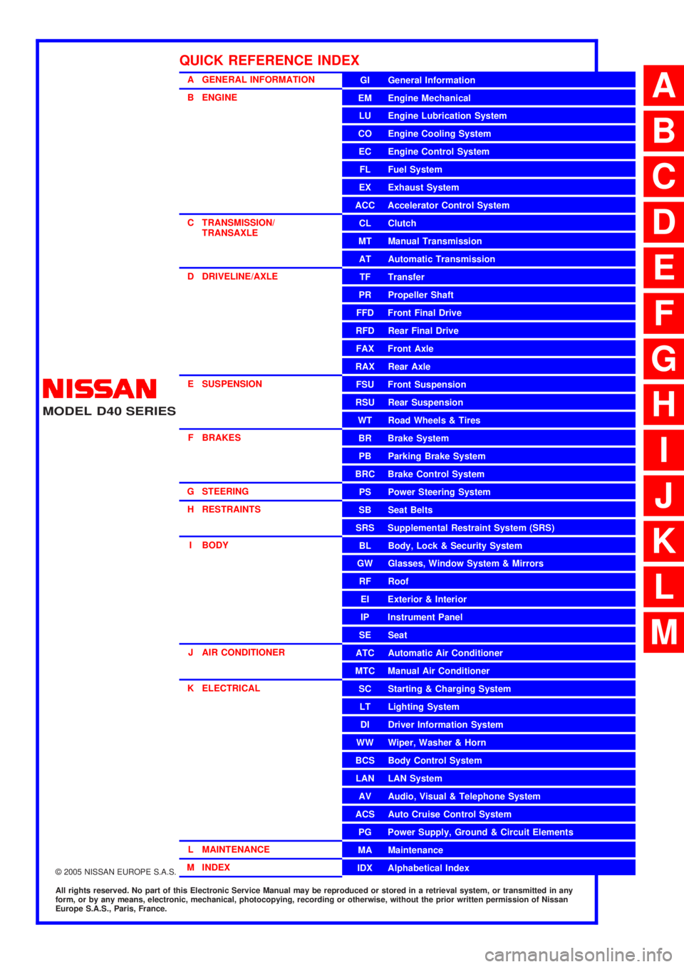
A GENERAL INFORMATION
B ENGINE
C TRANSMISSION/TRANSAXLE
D DRIVELINE/AXLE
E SUSPENSION F BRAKES
G STEERING H RESTRAINTS
I BODY
J AIR CONDITIONER
K ELECTRICAL
L MAINTENANCE
M INDEXGI General Information
EM Engine Mechanical
LU Engine Lubrication System
CO Engine Cooling System
EC Engine Control System
FL Fuel System
EX Exhaust System
ACC Accelerator Control System
CL Clutch
MTManualTransmission
AT Automatic Transmission
TF Transfer
PR Propeller Shaft
FFD Front Final Drive
RFD Rear Final Drive
FAX Front Axle
RAX Rear Axle
FSU Front Suspension
RSU Rear Suspension
WT Road Wheels & Tires
BR Brake System
PB Parking Brake System
BRC Brake Control System
PS Power Steering System
SB Seat Belts
SRS Supplemental Restraint System (SRS)
BL Body, Lock & Security System
GW Glasses, Window System & Mirrors
RF Roof
EI Exterior & Interior
IP Instrument Panel
SE Seat
ATC Automatic Air Conditioner
MTC Manual Air Conditioner
SC Starting & Charging System
LT Lighting System
DI Driver Information System
WW Wiper, Washer & Horn
BCS Body Control System
LAN LAN System
AV Audio, Visual & Telephone System
ACS Auto Cruise Control System
PG Power Supply, Ground & Circuit Elements
MA Maintenance
IDX Alphabetical Index
QUICK REFERENCE INDEX
A
B
C
D
E
F
G
H
I
J
K
L
M
Page 58 of 3171

AT-50
TROUBLE DIAGNOSIS
8.CHECK LOCK-UP RELEASE
Check lock-up cancellation by depressing brake pedal lightly to decelerate.
With CONSULT-II
Select “TCC SOLENOID” with “MAIN SIGNALS” mode for “A/T”. Refer toAT-77, "
CONSULT-II REFERENCE
VA L U E".
Does lock-up cancel?
YES >> GO TO 9.
NO >> Enter a check mark at “Lock-up Is Not Released” onAT-38, "
DIAGNOSTIC WORKSHEET",then
continue the road test.
9.CHECK SHIFT-DOWN D5®D4
Decelerate by pressing lightly on brake pedal.
With CONSULT-II
Read the gear position and engine speed. Refer toAT-83, "
DATA MONITOR MODE".
When the A/T shift-down D
5®D4, does the engine speed drop smoothly back to idle?
YES >> 1. Stop the vehicle.
2. Go toAT-50, "
Cruise Test - Part 2".
NO >> Enter a check mark at “Engine Speed Does Not Return to Idle” onAT-38, "
DIAGNOSTIC WORK-
SHEET", then continue the road test. Go toAT-50, "Cruise Test - Part 2".
CruiseTest-Part2ECS00FX4
1.CHECK STARTING FROM D1
1. Move selector lever to “D” position.
2. Accelerate at half throttle.
With CONSULT-II
Read the gear position. Refer toAT-83, "
DATA MONITOR MODE".
Does it start from D
1?
YES >> GO TO 2.
NO >> Enter a check mark at “Vehicle Cannot Be Started from D
1”onAT-38, "DIAGNOSTIC WORK-
SHEET", then continue the road test.
2.CHECK SHIFT-UP D1®D2
Press accelerator pedal down all the way and inspect whether or not the A/T shifts up (D1®D2)atthecor-
rect speed. Refer toAT-52, "
Vehicle Speed at Which Gear Shifting Occurs".
With CONSULT-II
Read the gear position, throttle degree and vehicle speed. Refer toAT-83, "
DATA MONITOR MODE".
Does the A/T shift-up D
1®D2at the correct speed?
YES >> GO TO 3.
NO >> Enter a check mark at “A/T Does Not Shift: D
1®D2”onAT-38, "DIAGNOSTIC WORKSHEET",
then continue the road test.
3.CHECK SHIFT-UP D2®D3
Press accelerator pedal down all the way and inspect whether or not the A/T shifts up (D2®D3)atthecor-
rect speed. Refer toAT-52, "
Vehicle Speed at Which Gear Shifting Occurs".
With CONSULT-II
Read the gear position, throttle degree and vehicle speed. Refer toAT-83, "
DATA MONITOR MODE".
Does the A/T shift-up D
2®D3at the correct speed?
YES >> GO TO 4.
NO >> Enter a check mark at “A/T Does Not Shift: D
2®D3”onAT-38, "DIAGNOSTIC WORKSHEET",
then continue the road test.
Page 85 of 3171

TROUBLE DIAGNOSIS
AT-77
D
E
F
G
H
I
J
K
L
MA
B
AT
CONSULT-II Function (A/T)ECS00FXA
CONSULT-II can display each diagnostic item using the diagnostic test modes shown following.
FUNCTION
CONSULT-II REFERENCE VALUE
NOTICE:
1. The CONSULT-II electrically displays shift timing and lock-up timing (that is, operation timing of each sole-
noid).
Check for time difference between actual shift timing and the CONSULT-II display. If the difference is
noticeable, mechanical parts (except solenoids, sensors, etc.) may be malfunctioning. Check mechanical
parts using applicable diagnostic procedures.
2. Shift schedule (which implies gear position) displayed on CONSULT-II and that indicated in Service Man-
ual may differ slightly. This occurs because of the following reasons:
–Actual shift schedule has more or less tolerance or allowance,
–Shift schedule indicated in Service Manual refers to the point where shifts start, and
–Gear position displayed on CONSULT-II indicates the point where shifts are completed.
3. Display of solenoid valves on CONSULT-II changes at the start of shifting, while gear position is displayed
upon completion of shifting (which is computed by TCM).
Diagnostic test mode Function Reference page
Self-diagnostic results Self-diagnostic results can be read and erased quickly.AT- 8 0
Data monitor Input/Output data in the ECU can be read.AT- 8 3
CAN diagnostic support
monitorThe results of transmit/receive diagnosis of CAN communication can be read.AT- 8 6
Function testConducted by CONSULT-II instead of a technician to determine whether each system
is “OK” or “NG”.—
DTC work support Select the operating condition to confirm Diagnostic Trouble Codes.AT- 8 6
ECU part number ECU part number can be read. —
Item name Condition Display value (Approx.)
VHCL/S SE-A/T
During drivingApproximately matches the speed-
ometer reading.
VHCL/S SE-MTR
ACCELE POSIReleased accelerator pedal. 0.0/8
Fully depressed accelerator pedal. 8.0/8
CLSD THL POSReleased accelerator pedal. ON
Fully depressed accelerator pedal. OFF
W/O THL POSFully depressed accelerator pedal. ON
Released accelerator pedal. OFF
BRAKE SWDepressed brake pedal. ON
Released brake pedal. OFF
ENGINE SPEED Engine runningClosely matches the tachometer
reading.
TURBINE REV During driving (lock-up ON)Approximately matches the engine
speed.
ATFTEMPSE1
0°C(32°F)-20°C(68°F)-80°C (176°F)3.3 - 2.7 - 0.9 V
ATFTEMPSE23.3 - 2.5 - 0.7 V
TCC SOLENOID When perform lock-up 0.4 - 0.6 A
LINE PRES SOL During driving 0.2 - 0.6 A
FR/B SOLENOIDFront brake engaged. Refer toAT- 1 7
. 0.6 - 0.8 A
Front brake disengaged. Refer toAT- 1 7
.0-0.05A
Page 97 of 3171

TROUBLE DIAGNOSIS
AT-89
D
E
F
G
H
I
J
K
L
MA
B
AT
Diagnostic Procedure Without CONSULT-IIECS00FXB
TCM SELF-DIAGNOSTIC PROCEDURE (WITHOUT CONSULT-II)
Description
In the unlikely event of a malfunction in the electrical system, when the ignition switch is switched ON, the OD
OFF indicator lamp lights up for 2 seconds. If there is no malfunction, when the ignition switch is turned ON,
the indicator lamp lights up for 2 seconds. As a method for locating the suspect circuit, when the self-diagnos-
tics start signal is input, the memory for the malfunction location is output and OD OFF indicator lamp flashes
to display the corresponding DTC.
Diagnostic Procedure
1.CHECK OD OFF INDICATOR LAMP
1. Start the engine with selector lever in “P” position. Warm engine to normal operating temperature.
2. Turn ignition switch ON and OFF at least twice, then leave it in the OFF position.
3. Wait 10 seconds.
4. Turn ignition switch ON. (Do not start engine.)
Does OD OFF indicator lamp come on for about 2 seconds?
YES >> GO TO 2.
NO >> GO TOAT- 1 7 7 , "
OD OFF Indicator Lamp Does Not Come On".
2.JUDGEMENT PROCEDURE
1. Turn ignition switch OFF.
2. Keep pressing shift lock release button.
3. Move selector lever from “P” to “D” position.
4. Release accelerator pedal. (Set the closed throttle position signal ON.)
5. Depress brake pedal. (Stop lamp switch signal ON.)
6. Turn ignition switch ON.
7. Wait 3 seconds.
8. Move selector lever from “D” to “3” position.
9. Release brake pedal. (Stop lamp switch signal OFF.)
10. Move selector lever from “3” to “2” position.
11. Depress brake pedal. (Stop lamp switch signal ON.)
12. Release brake pedal. (Stop lamp switch signal OFF.)
13. Depress accelerator pedal fully and release it.
>> GO TO 3.
3.CHECK SELF-DIAGNOSIS CODE
Check OD OFF indicator lamp. Refer toAT-90, "
Judgement Self-diagnosis Code".
If the system does not go into self-diagnosis. Refer toAT-99, "
DTC P0705 PARK/NEUTRAL POSITION
SWITCH",AT- 1 6 8 , "CLOSED THROTTLE POSITION AND WIDE OPEN THROTTLE POSITION CIRCUIT",
AT- 1 6 9 , "
BRAKE SIGNAL CIRCUIT".
>>DIAGNOSIS END
Page 98 of 3171

AT-90
TROUBLE DIAGNOSIS
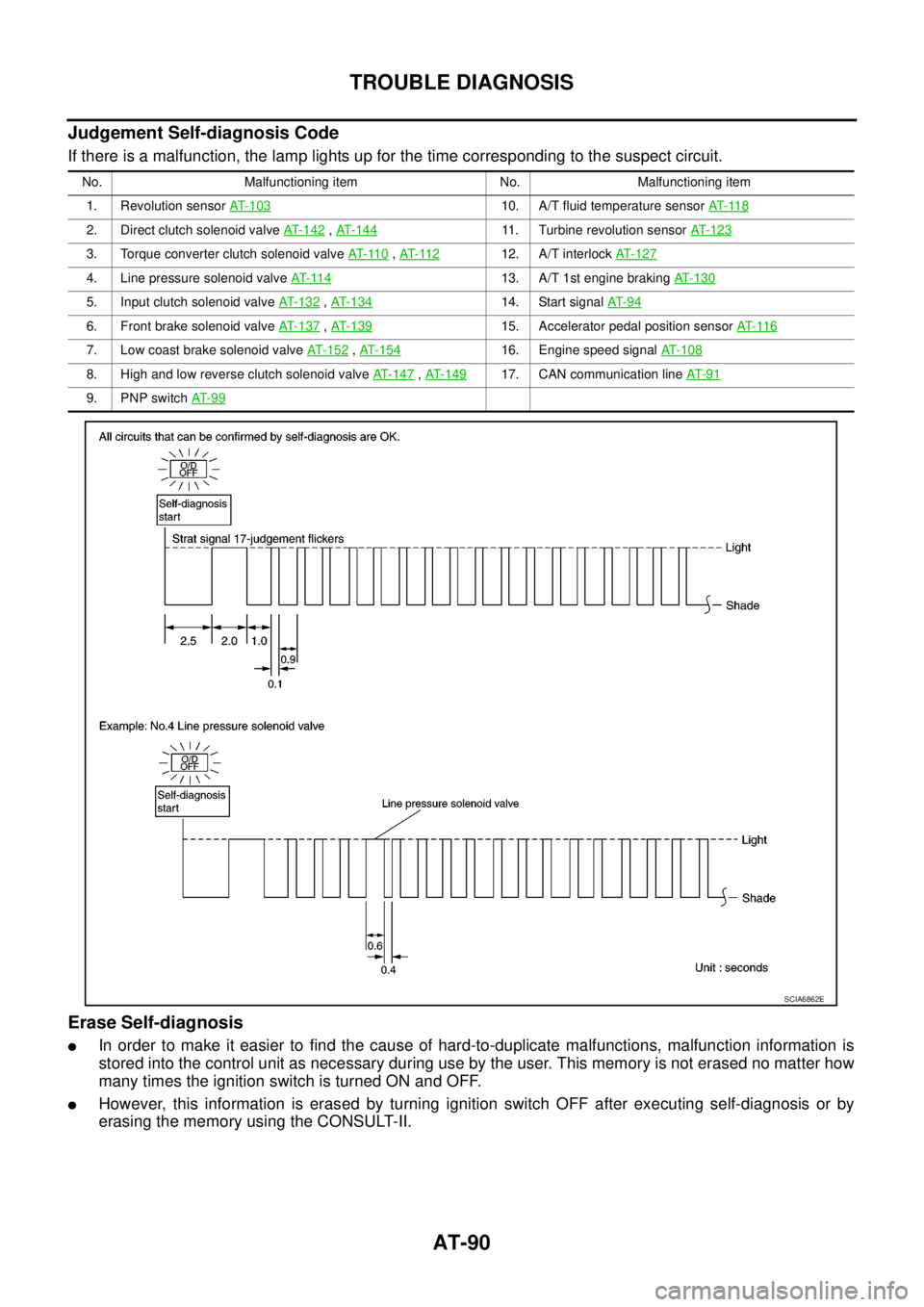
Judgement Self-diagnosis Code
If there is a malfunction, the lamp lights up for the time corresponding to the suspect circuit.
Erase Self-diagnosis
lIn order to make it easier to find the cause of hard-to-duplicate malfunctions, malfunction information is
stored into the control unit as necessary during use by the user. This memory is not erased no matter how
many times the ignition switch is turned ON and OFF.
lHowever, this information is erased by turning ignition switch OFF after executing self-diagnosis or by
erasing the memory using the CONSULT-II.
No. Malfunctioning item No. Malfunctioning item
1. Revolution sensorAT- 1 0 3
10. A/T fluid temperature sensorAT- 11 8
2. Direct clutch solenoid valveAT- 1 4 2,AT-14411. Turbine revolution sensorAT- 1 2 3
3. Torque converter clutch solenoid valveAT- 11 0,AT- 11 212. A/T interlockAT-127
4. Line pressure solenoid valveAT- 11 413. A/T 1st engine brakingAT-130
5. Input clutch solenoid valveAT- 1 3 2,AT- 1 3 414. Start signalAT- 9 4
6. Front brake solenoid valveAT-137,AT- 1 3 915. Accelerator pedal position sensorAT- 11 6
7. Low coast brake solenoid valveAT- 1 5 2,AT- 1 5 416. Engine speed signalAT-108
8. High and low reverse clutch solenoid valveAT-147,AT- 1 4 917. CAN communication lineAT- 9 1
9. PNP switchAT- 9 9
SCIA6862E
Page 528 of 3171

AV-40
TERMINALS AND REFERENCE VALUE FOR CONTROL UNIT
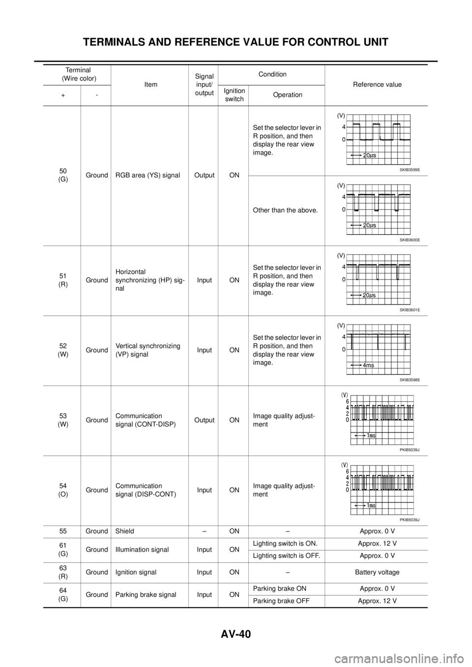
50
(G)Ground RGB area (YS) signal Output ONSet the selector lever in
R position, and then
display the rear view
image.
Other than the above.
51
(R)GroundHorizontal
synchronizing (HP) sig-
nalInput ONSet the selector lever in
R position, and then
display the rear view
image.
52
(W)GroundVertical synchronizing
(VP) signalInput ONSet the selector lever in
R position, and then
display the rear view
image.
53
(W)GroundCommunication
signal (CONT-DISP)Output ONImage quality adjust-
ment
54
(O)GroundCommunication
signal (DISP-CONT)Input ONImage quality adjust-
ment
55 Ground Shield – ON – Approx. 0 V
61
(G)Ground Illumination signal Input ONLighting switch is ON. Approx. 12 V
Lighting switch is OFF. Approx. 0 V
63
(R)Ground Ignition signal Input ON – Battery voltage
64
(G)Ground Parking brake signal Input ONParking brake ON Approx. 0 V
Parking brake OFF Approx. 12 V Terminal
(Wire color)
ItemSignal
input/
outputCondition
Reference value
+-Ignition
switchOperationSKIB3599E
SKIB3600E
SKIB3601E
SKIB3598E
PKIB5039J
PKIB5039J
Page 532 of 3171

AV-44
DIAGNOSIS SYSTEM
DIAGNOSIS SYSTEM
PFP:00000
Navigation System Diagnosis FunctionEKS00Q6H
lThere are 2 diagnosis functions (on board diagnosis and diagnosis using CONSULT-II), and it is neces-
sary to use them properly according to the condition. If the on board diagnosis starts, perform diagnosis
with on board diagnosis. If the on board diagnosis does not start (the cause being that the system is not
started, the switch operation is not activated, etc.), perform diagnosis using CONSULT-II.
lAt on board diagnosis, the NAVI control unit diagnosis function starts by switch operation and the NAVI
control unit performs the diagnosis for each unit of system.
lAt diagnosis using CONSULT-II, the NAVI control unit diagnosis function starts by the communication
between CONSULT-II and NAVI control unit, and the NAVI control unit performs the diagnosis for each
unit of system.
On Bord Self-Diagnosis FunctionEKS00Q6I
DESCRIPTION
lThe on board diagnosis function has a self-diagnosis mode for performing trouble diagnosis automatically
and a Confirmation/Adjustment mode for operating manually.
lSelf-diagnosis mode performs the diagnosis at NAVI control unit, connections between each unit that
composes the system, and connections between NAVI control unit and GPS antenna. It displays the
results on the display.
lConfirmation/Adjustment mode is used to monitor the vehicle signals requiring operation and judgement
by a technician (malfunctions that cannot be automatically judged by the system), the confirmation/adjust-
ment of setting value, the error history of system, and the communication condition of system.
DIAGNOSIS ITEM
Mode Description
Self Diagnosis
lNAVI control unit diagnosis (DVD-ROM drive will not be diagnosed when
no map DVD-ROM is in it.)
lThe connection diagnosis between NAVI control unit and GPS antenna
and the connection diagnosis between NAVI control unit and each unit
can be performed.
Confirma-
tion/Adjust-
mentDisplay DiagnosisThe tint can be confirmed by the color spectrum bar display. The shading
of color can be confirmed by the gradation bar display.
Vehicle SignalsDiagnosis of signals can be performed for vehicle speed, parking brake,
lights, ignition (ignition switch), and reverse.
Speaker Test The connection of a speaker can be confirmed by test tone.
NavigationSteering Angle
AdjustmentWhen there is a difference between the actual turning angle and the vehi-
cle mark turning angle, it can be adjusted.
Speed CalibrationWhen there is a difference between the current location mark and the
actual location, it can be adjusted.
Error HistoryThe system malfunction and its frequency that occurred in the past are dis-
played. When the malfunctioning item is selected, the time and place that
the selected malfunction last occurred are displayed.
Vehicle CAN Diagnosis The transmitting/receiving of CAN communication can be monitored.
AV COMM DiagnosisThe communication condition of each unit that composes the system can
be monitored.
Handsfree PhoneEach setting of hands-free volume adjustment, voice microphone test,
delete hands-free memory can be performed.
Bluetooth Passkey and device name can be confirmed/changed.
Delete Unit Commection Log The connection history and error history of unit can be deleted.
Page 537 of 3171

DIAGNOSIS SYSTEM
AV-49
C
D
E
F
G
H
I
J
L
MA
B
AV
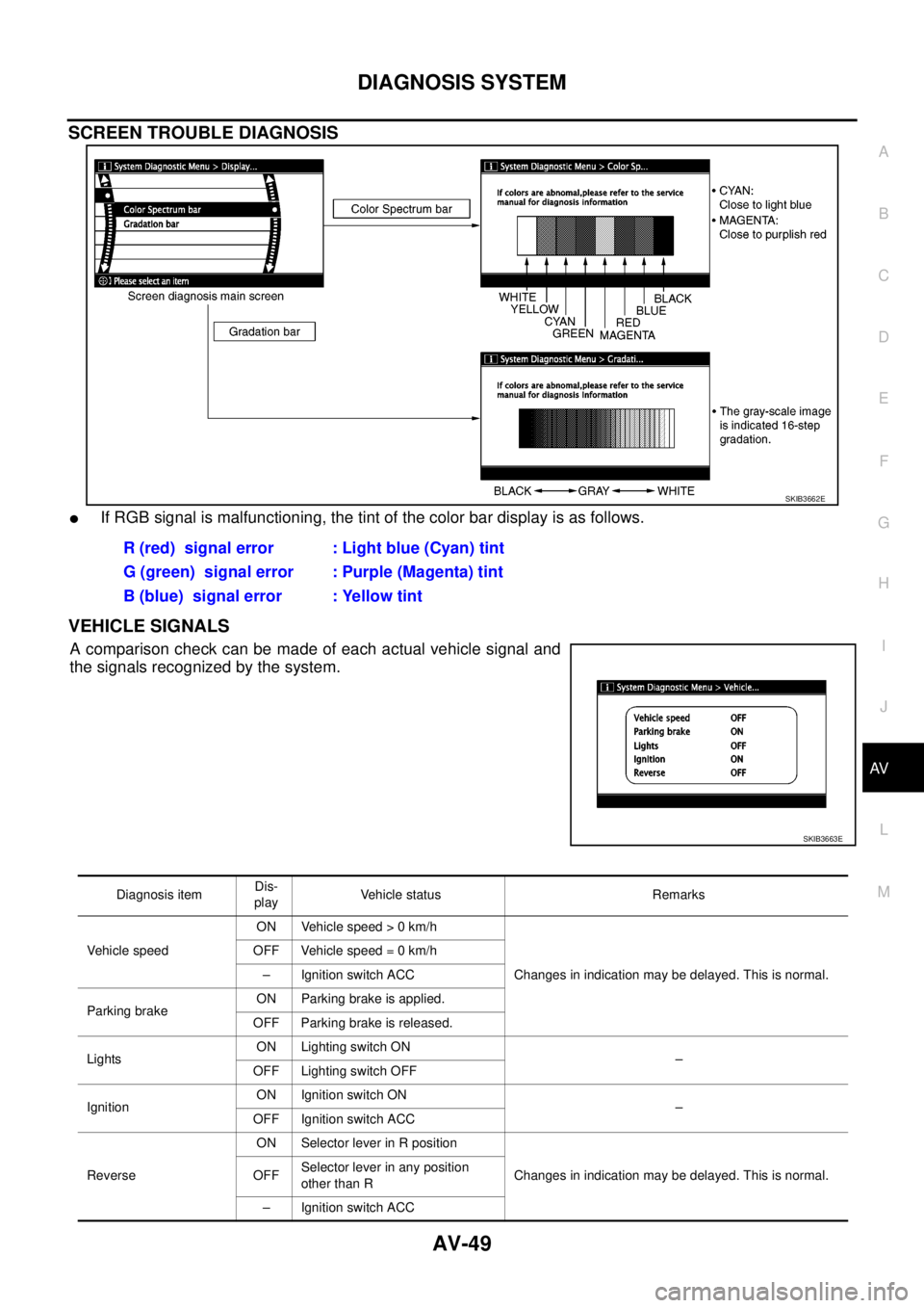
SCREEN TROUBLE DIAGNOSIS
lIf RGB signal is malfunctioning, the tint of the color bar display is as follows.
VEHICLE SIGNALS
Acomparisoncheckcanbemadeofeachactualvehiclesignaland
the signals recognized by the system.
SKIB3662E
R (red) signal error : Light blue (Cyan) tint
G (green) signal error : Purple (Magenta) tint
B (blue) signal error : Yellow tint
SKIB3663E
Diagnosis itemDis-
playVehicle status Remarks
Vehicle speedON Vehicle speed > 0 km/h
Changes in indication may be delayed. This is normal. OFF Vehicle speed = 0 km/h
– Ignition switch ACC
Parking brakeON Parking brake is applied.
OFF Parking brake is released.
LightsON Lighting switch ON
–
OFF Lighting switch OFF
IgnitionON Ignition switch ON
–
OFF Ignition switch ACC
ReverseON Selector lever in R position
Changes in indication may be delayed. This is normal. OFFSelector lever in any position
other than R
– Ignition switch ACC