2005 NISSAN NAVARA engine overheat
[x] Cancel search: engine overheatPage 431 of 3171
TROUBLE DIAGNOSIS
ATC-97
C
D
E
F
G
H
I
K
L
MA
B
AT C
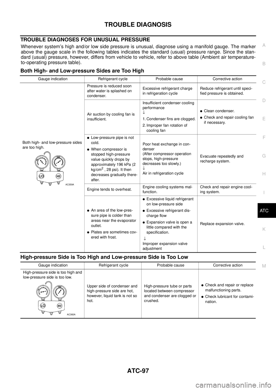
TROUBLE DIAGNOSES FOR UNUSUAL PRESSURE
Whenever system¢s high and/or low side pressure is unusual, diagnose using a manifold gauge. The marker
above the gauge scale in the following tables indicates the standard (usual) pressure range. Since the stan-
dard (usual) pressure, however, differs from vehicle to vehicle, refer to above table (Ambient air temperature-
to-operating pressure table).
Both High- and Low-pressure Sides are Too High
High-pressure Side is Too High and Low-pressure Side is Too Low
Gauge indication Refrigerant cycle Probable cause Corrective action
Both high- and low-pressure sides
are too high.Pressure is reduced soon
after water is splashed on
condenser.Excessive refrigerant charge
in refrigeration cycleReduce refrigerant until speci-
fied pressure is obtained.
Air suction by cooling fan is
insufficient.Insufficient condenser cooling
performance
¯
1. Condenser fins are clogged.
2. Improper fan rotation of
cooling fan
lClean condenser.
lCheck and repair cooling fan
if necessary.
lLow-pressure pipe is not
cold.
lWhen compressor is
stopped high-pressure
value quickly drops by
approximately 196 kPa (2
kg/cm
2, 28 psi). It then
decreases gradually there-
after.Poor heat exchange in con-
denser
(After compressor operation
stops, high-pressure
decreases too slowly.)
¯
Air in refrigeration cycleEvacuate repeatedly and
recharge system.
Engine tends to overheat.Engine cooling systems mal-
function.Check and repair engine cool-
ing system.
lAn area of the low-pres-
sure pipe is colder than
areas near the evaporator
outlet.
lPlates are sometimes cov-
ered with frost.
lExcessive liquid refrigerant
on low-pressure side
lExcessive refrigerant dis-
charge flow
lExpansion valve is open a
little compared with the
specification.
¯
Improper expansion valve
adjustmentReplace expansion valve.
AC359A
Gauge indication Refrigerant cycle Probable cause Corrective action
High-pressure side is too high and
low-pressure side is too low.
Upper side of condenser and
high-pressure side are hot,
however, liquid tank is not so
hot.High-pressure tube or parts
located between compressor
and condenser are clogged or
crushed.
lCheck and repair or replace
malfunctioning parts.
lCheck lubricant for contami-
nation.
AC360A
Page 885 of 3171
CO-1
ENGINE COOLING SYSTEM
B ENGINE
CONTENTS
C
D
E
F
G
H
I
J
K
L
M
SECTIONCO
A
CO
ENGINE COOLING SYSTEM
PRECAUTIONS .......................................................... 2
Precautions For Liquid Gasket ................................. 2
LIQUID GASKET APPLICATION PROCEDURE..... 2
PREPARATION ........................................................... 3
Special Service Tools ............................................... 3
Commercial Service Tools ........................................ 3
OVERHEATING CAUSE ANALYSIS .......................... 4
Troubleshooting Chart .............................................. 4
COOLING SYSTEM .................................................... 6
Cooling Circuit .......................................................... 6
ENGINE COOLANT .................................................... 7
Inspection ................................................................. 7
LEVEL CHECK ..................................................... 7
CHECKING RADIATOR SYSTEM FOR LEAKS..... 7
Changing Engine Coolant ........................................ 7
DRAINING ENGINE COOLANT ........................... 8
REFILLING ENGINE COOLANT .......................... 8
FLUSHING COOLING SYSTEM ........................... 9
RADIATOR .................................................................11
Components ............................................................ 11
Removal and Installation ......................................... 11
REMOVAL ............................................................ 11
INSPECTION AFTER REMOVAL ....................... 13
INSTALLATION ................................................... 14
INSPECTION AFTER INSTALLATION ............... 14
RADIATOR (ALUMINUM TYPE) .............................. 15
Components ........................................................... 15
Disassembly and Assembly ................................... 15
PREPARATION ................................................... 15
DISASSEMBLY ................................................... 15
ASSEMBLY ......................................................... 16
INSPECTION ...................................................... 18COOLING FAN .......................................................... 19
Components (Crankshaft Driven Type) .................. 19
Removal and Installation ........................................ 19
REMOVAL ........................................................... 19
INSPECTION AFTER REMOVAL ....................... 19
INSTALLATION ................................................... 19
Removal and Installation (Motor Driven Type) (Mod-
els with A/C) ........................................................... 19
REMOVAL ........................................................... 19
INSTALLATION ................................................... 20
WATER PUMP .......................................................... 21
Components ........................................................... 21
Removal and Installation ........................................ 21
REMOVAL ........................................................... 21
INSPECTION AFTER REMOVAL ....................... 22
INSTALLATION ................................................... 22
INSPECTION AFTER INSTALLATION ................ 22
THERMOSTAT AND WATER PIPING ...................... 23
Components ........................................................... 23
Removal and Installation ........................................ 24
REMOVAL ........................................................... 24
INSPECTION AFTER REMOVAL ....................... 24
INSTALLATION ................................................... 24
INSPECTION AFTER INSTALLATION ................ 25
SERVICE DATA AND SPECIFICATIONS (SDS) ...... 26
Standard and Limit .................................................. 26
ENGINE COOLANT CAPACITY .......................... 26
THERMOSTAT .................................................... 26
RESERVOIR TANK ............................................. 26
Page 888 of 3171
CO-4
OVERHEATING CAUSE ANALYSIS
OVERHEATING CAUSE ANALYSIS
PFP:00012
Troubleshooting ChartEBS01E6M
Symptom Check items
Cooling sys-
tem parts
malfunctionPoor heat transferWater pump malfunction Worn or loose drive belt
— Thermostat stuck closed —
Damaged finsDust contamination or
paper clogging
Physical damage
Clogged radiator cooling
tubeExcess foreign material
(rust, dirt, sand, etc.)
Reduced air flowCooling fan does not oper-
ateRefer toEC-132, "
DTC
P0217 ENGINE OVER
TEMPERATURE"
—
Highresistancetofanrota-
tion
Fan assembly
Damaged fan blades
Damaged radiator shroud — — —
Improper engine coolant
mixture ratio—— —
Poor engine coolant quality — Engine coolant density —
Insufficient engine coolantEngine coolant leaksCooling hoseLoose clamp
Cracked hose
Water pump Poor sealing
Radiator capLoose
Poor sealing
RadiatorO-ring for damage, deterio-
ration or improper fitting
Cracked radiator tank
Cracked radiator core
Reservoir tank Cracked reservoir tank
Overflowing reservoir tankExhaust gas leaks into
cooling systemCylinder head deterioration
Cylinder head gasket dete-
rioration
Page 889 of 3171

OVERHEATING CAUSE ANALYSIS
CO-5
C
D
E
F
G
H
I
J
K
L
MA
CO
Except cool-
ing system
parts mal-
function— Overload on engineAbusive drivingHigh engine rpm under no
load
Driving in low gear for
extended time
Driving at extremely high
speed
Powertrain system mal-
function
— Installed improper size
wheels and tires
Dragging brakes
Improper ignition timing
Blocked or restricted air
flowBlocked bumper —
— Blocked radiator grilleInstalled car brassiere
Mud contamination or
paper clogging
Blocked radiator —
Blocked condenser
Blocked air flow
Installed large fog lamp Symptom Check items
Page 893 of 3171
ENGINE COOLANT
CO-9
C
D
E
F
G
H
I
J
K
L
MA
CO
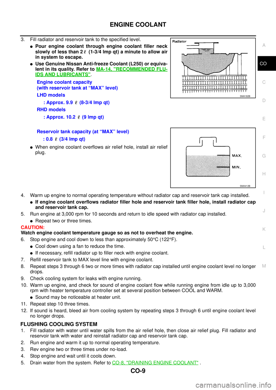
3. Fill radiator and reservoir tank to the specified level.
lPour engine coolant through engine coolant filler neck
slowly of less than 2 (1-3/4 lmp qt) a minute to allow air
in system to escape.
lUse Genuine Nissan Anti-freeze Coolant (L250) or equiva-
lent in its quality. Refer toMA-14, "
RECOMMENDED FLU-
IDS AND LUBRICANTS".
lWhen engine coolant overflows air relief hole, install air relief
plug.
4. Warm up engine to normal operating temperature without radiator cap and reservoir tank cap installed.
lIf engine coolant overflows radiator filler hole and reservoir tank filler hole, install radiator cap
and reservoir tank cap.
5. Run engine at 3,000 rpm for 10 seconds and return to idle speed with radiator cap installed.
lRepeat two or three times.
CAUTION:
Watch engine coolant temperature gauge so as not to overheat the engine.
6. Stop engine and cool down to less than approximately 50°C(122°F).
lCool down using a fan to reduce the time.
lIf necessary, refill radiator up to filler neck with engine coolant.
7. Refill reservoir tank to MAX level line with engine coolant.
8. Repeat steps 3 through 6 two or more times with radiator cap installed until engine coolant level no longer
drops.
9. Check cooling system for leaks with engine running.
10. Warm up engine, and check for sound of engine coolant flow while running engine from idle up to 3,000
rpm with heater temperature controller set at several position between COOL and WARM.
lSound may be noticeable at heater unit.
11. Repeat step 10 three times.
12. If sound is heard, bleed air from cooling system by repeating steps 3 through 6 until engine coolant level
no longer drops.
FLUSHING COOLING SYSTEM
1. Fill radiator with water until water spills from the air relief hole, then close air relief plug. Fill radiator and
reservoir tank with water and reinstall radiator cap and reservoir tank cap.
2. Run engine and warm it up to normal operating temperature.
3. Rev engine two or three times under no-load.
4. Stop engine and wait until it cools down.
5. Drain water from the system. Refer toCO-8, "
DRAINING ENGINE COOLANT". Engine coolant capacity
(with reservoir tank at “MAX” level)
LHD models
: Approx. 9.9 (8-3/4 lmp qt)
RHD models
: Approx. 10.2 (9 lmp qt)
SMA182B
Reservoir tank capacity (at “MAX” level)
: 0.8 (3/4 lmp qt)
SMA412B
Page 982 of 3171

EC-2
DTC Confirmation Procedure ................................. 88
Diagnostic Procedure ............................................. 89
Component Inspection ............................................ 90
Removal and Installation ........................................ 91
DTC P0102, P0103 MAF SENSOR ........................... 92
Component Description .......................................... 92
CONSULT-II Reference Value in Data Monitor Mode
... 92
ECM Terminals and Reference Value ..................... 92
On Board Diagnosis Logic ...................................... 93
DTC Confirmation Procedure ................................. 93
Wiring Diagram ....................................................... 94
Diagnostic Procedure ............................................. 95
Component Inspection ............................................ 96
Removal and Installation ........................................ 97
DTC P0112, P0113 IAT SENSOR ............................. 98
Component Description .......................................... 98
On Board Diagnosis Logic ...................................... 98
DTC Confirmation Procedure ................................. 98
Wiring Diagram .....................................................100
Diagnostic Procedure ...........................................101
Component Inspection ..........................................102
Removal and Installation ......................................102
DTC P0117, P0118 ECT SENSOR ..........................103
Description ............................................................103
On Board Diagnosis Logic ....................................103
DTC Confirmation Procedure ...............................103
Wiring Diagram .....................................................105
Diagnostic Procedure ...........................................106
Component Inspection ..........................................107
Removal and Installation ......................................107
DTC P0122, P0123 APP SENSOR .........................108
Description ............................................................108
CONSULT-II Reference Value in Data Monitor Mode
.108
ECM Terminals and Reference Value ...................108
On Board Diagnosis Logic ....................................109
DTC Confirmation Procedure ...............................109
Wiring Diagram .....................................................110
Diagnostic Procedure ............................................111
Component Inspection ..........................................112
Removal and Installation ......................................112
DTC P0182, P0183 FUEL PUMP TEMPERATURE
SENSOR ..................................................................113
Description ............................................................113
CONSULT-II Reference Value in Data Monitor Mode
.113
ECM Terminals and Reference Value ...................113
On Board Diagnosis Logic ....................................113
DTC Confirmation Procedure ...............................114
Wiring Diagram .....................................................115
Diagnostic Procedure ...........................................116
Removal and Installation ......................................117
DTC P0192, P0193 FRP SENSOR .........................118
Description ............................................................118
CONSULT-II Reference Value in Data Monitor Mode
.118
ECM Terminals and Reference Value ...................118
On Board Diagnosis Logic ....................................118DTC Confirmation Procedure ................................119
Wiring Diagram .....................................................120
Diagnostic Procedure ............................................121
Component Inspection ..........................................122
Removal and Installation .......................................122
DTC P0200 FUEL INJECTOR .................................123
On Board Diagnosis Logic ....................................123
DTC Confirmation Procedure ................................123
Diagnostic Procedure ............................................123
DTC P0201 - P0204 FUEL INJECTOR ...................125
Component Description ........................................125
CONSULT-II Reference Value in Data Monitor Mode
.125
ECM Terminals and Reference Value ...................125
On Board Diagnosis Logic ....................................126
DTC Confirmation Procedure ................................127
Wiring Diagram .....................................................128
Diagnostic Procedure ............................................129
Component Inspection ..........................................130
Removal and Installation .......................................131
DTC P0217 ENGINE OVER TEMPERATURE ........132
Description ............................................................132
CONSULT-II Reference Value in Data Monitor Mode
.133
On Board Diagnosis Logic ....................................133
Overall Function Check .........................................133
Wiring Diagram .....................................................135
Diagnostic Procedure ............................................137
Main 12 Causes of Overheating ...........................140
Component Inspection ..........................................141
DTC P0222, P0223 APP SENSOR .........................142
Description ............................................................142
CONSULT-II Reference Value in Data Monitor Mode
.142
ECM Terminals and Reference Value ...................142
On Board Diagnosis Logic ....................................143
DTC Confirmation Procedure ................................143
Wiring Diagram .....................................................144
Diagnostic Procedure ............................................145
Component Inspection ..........................................146
Removal and Installation .......................................146
DTC P0234 TC SYSTEM .........................................147
Description ............................................................147
ECM Terminals and Reference Value ...................147
On Board Diagnosis Logic ....................................148
Overall Function Check .........................................148
Wiring Diagram .....................................................149
Diagnostic Procedure ............................................150
Component Inspection ..........................................152
Removal and Installation .......................................152
DTC P0237, P0238 TC BOOST SENSOR ..............153
Component Description ........................................153
CONSULT-II Reference Value in Data Monitor Mode
.153
ECM Terminals and Reference Value ...................153
On Board Diagnosis Logic ....................................154
DTC Confirmation Procedure ................................154
Wiring Diagram .....................................................155
Diagnostic Procedure ............................................156
Page 1017 of 3171
TROUBLE DIAGNOSIS
EC-37
C
D
E
F
G
H
I
J
K
L
MA
EC
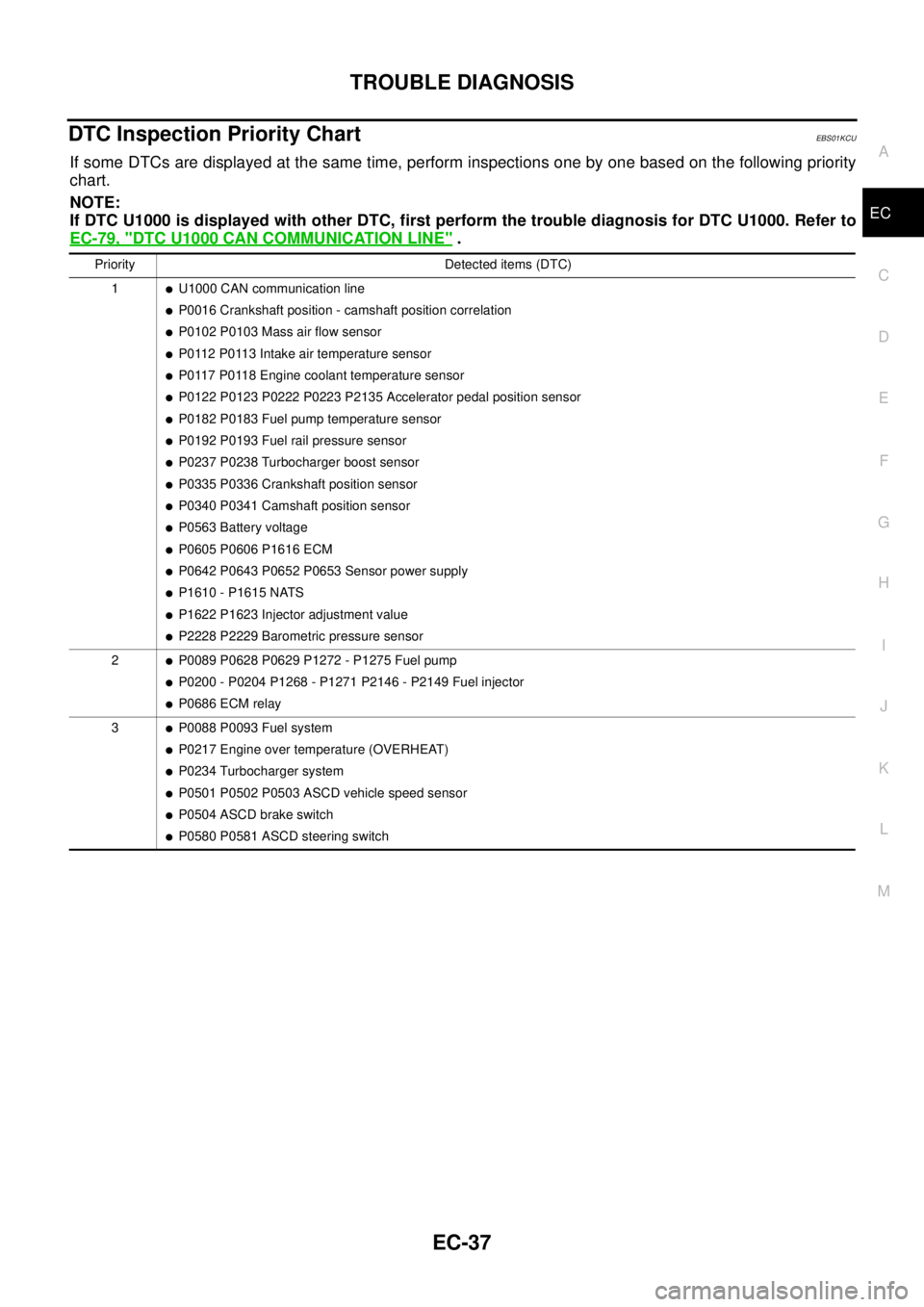
DTC Inspection Priority ChartEBS01KCU
If some DTCs are displayed at the same time, perform inspections one by one based on the following priority
chart.
NOTE:
If DTC U1000 is displayed with other DTC, first perform the trouble diagnosis for DTC U1000. Refer to
EC-79, "
DTC U1000 CAN COMMUNICATION LINE".
Priority Detected items (DTC)
1
lU1000 CAN communication line
lP0016 Crankshaft position - camshaft position correlation
lP0102 P0103 Mass air flow sensor
lP0112 P0113 Intake air temperature sensor
lP0117 P0118 Engine coolant temperature sensor
lP0122 P0123 P0222 P0223 P2135 Accelerator pedal position sensor
lP0182 P0183 Fuel pump temperature sensor
lP0192 P0193 Fuel rail pressure sensor
lP0237 P0238 Turbocharger boost sensor
lP0335 P0336 Crankshaft position sensor
lP0340 P0341 Camshaft position sensor
lP0563 Battery voltage
lP0605 P0606 P1616 ECM
lP0642 P0643 P0652 P0653 Sensor power supply
lP1610 - P1615 NATS
lP1622 P1623 Injector adjustment value
lP2228 P2229 Barometric pressure sensor
2
lP0089 P0628 P0629 P1272 - P1275 Fuel pump
lP0200 - P0204 P1268 - P1271 P2146 - P2149 Fuel injector
lP0686 ECM relay
3
lP0088 P0093 Fuel system
lP0217 Engine over temperature (OVERHEAT)
lP0234 Turbocharger system
lP0501 P0502 P0503 ASCD vehicle speed sensor
lP0504 ASCD brake switch
lP0580 P0581 ASCD steering switch
Page 1024 of 3171
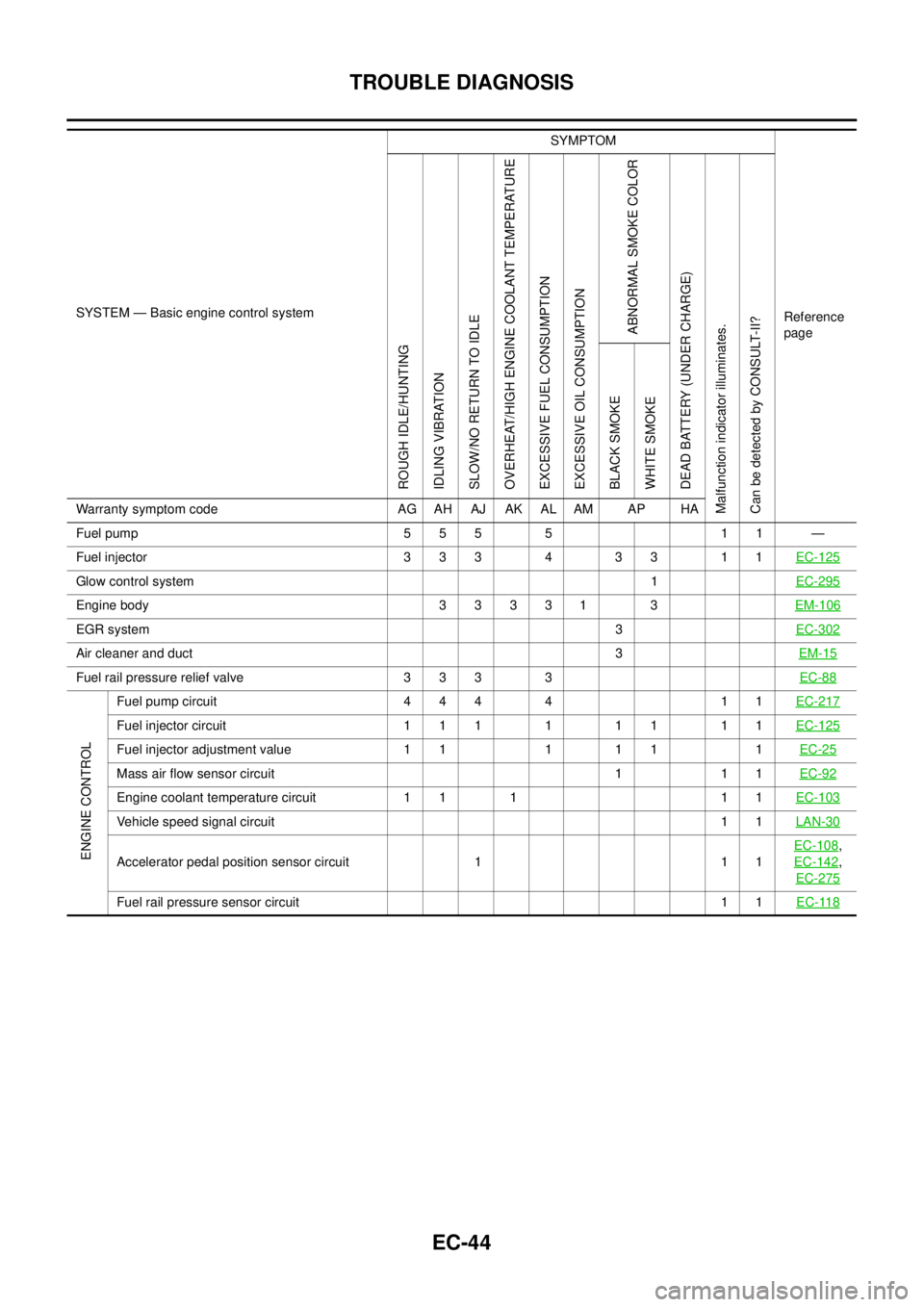
EC-44
TROUBLE DIAGNOSIS
SYSTEM — Basic engine control systemSYMPTOM
Reference
page
ROUGH IDLE/HUNTING
IDLING VIBRATION
SLOW/NO RETURN TO IDLE
OVERHEAT/HIGH ENGINE COOLANT TEMPERATURE
EXCESSIVE FUEL CONSUMPTION
EXCESSIVE OIL CONSUMPTION
ABNORMAL SMOKE COLOR
DEAD BATTERY (UNDER CHARGE)
Malfunction indicator illuminates.
Can be detected by CONSULT-II?BLACK SMOKE
WHITE SMOKE
Warranty symptom code AG AH AJ AK AL AM AP HA
Fuel pump 5 5 5 5 1 1 —
Fuel injector 3 3 3 4 3 3 1 1EC-125
Glow control system1EC-295
Engine body 3 3 3 3 1 3EM-106
EGR system3EC-302
Air cleaner and duct3EM-15
Fuel rail pressure relief valve 3 3 3 3EC-88
ENGINE CONTROL
Fuel pump circuit 4 4 4 4 1 1EC-217
Fuel injector circuit 1 1 1 1 1 1 1 1EC-125
Fuel injector adjustment value 1 1 1 1 1 1EC-25
Mass air flow sensor circuit 1 1 1EC-92
Engine coolant temperature circuit 1 1 1 1 1EC-103
Vehicle speed signal circuit11LAN-30
Accelerator pedal position sensor circuit 1 1 1EC-108
,
EC-142
,
EC-275
Fuel rail pressure sensor circuit11EC-118