2005 NISSAN NAVARA center console
[x] Cancel search: center consolePage 217 of 3171

SHIFT CONTROL SYSTEM
AT-209
D
E
F
G
H
I
J
K
L
MA
B
AT
REMOVAL
1. Remove knob cover (2) below selector lever knob (1) down-
ward.
2. Pull lock pin (3) out of selector lever knob (1).
3. Remove selector lever knob (1) and knob cover (2).
4. Remove center console. Refer toIP-16, "
CENTER CONSOLE".
5. Disconnect A/T device harness connector (1).
6. Disconnect key interlock cable (4) from control device assembly.
Refer toAT- 2 1 6 , "
Removal and Installation".
7. Remove lock plate (2) from control cable (3).
8. Disconnect control cable (3) from control device assembly.
9. Remove control device assembly.
: Bolt (4)
INSTALLATION
Note the following, and install in the reverse order of removal.
lAfter installation is completed, adjust and check A/T position. Refer toAT- 2 11 , "Adjustment of A/T Posi-
tion"andAT- 2 11 , "Checking of A/T Position".
SCIA7296E
SCIA7297E
SCIA7298E
Page 225 of 3171

KEY INTERLOCK CABLE
AT-217
D
E
F
G
H
I
J
K
L
MA
B
AT
REMOVAL
1. Remove center console. Refer toIP-16, "CENTER CONSOLE".
2. Remove lower instrument panel LH (for LHD models) or lower instrument panel RH (for RHD models) and
cluster lid A. Refer toIP-13, "
LOWER INSTRUMENT PANEL LH",IP-15, "LOWER INSTRUMENT
PANEL RH AND GLOVE BOX",IP-10, "INSTRUMENT PANEL".
3. Unlock slider by squeezing lock tabs on slider from adjuster
holder.
4. Remove casing cap from bracket of control device assembly
and remove interlock rod from adjuster holder.
5. Remove holder from key cylinder and remove key interlock
cable.
INSTALLATION
1. Set key interlock cable to key cylinder and install holder.
2. Turn ignition key to lock position.
3. Set selector lever to “P” position.
4. Insert interlock rod into adjuster holder.
5. Install casing cap to bracket.
6. Move slider in order to secure adjuster holder to interlock rod.
CAUTION:
Do not touch any other areas than slider or apply any force
to slider except in the sliding direction.
7. Install lower instrument panel LH (for LHD models) or lower
instrument panel RH (for RHD models) and cluster lid A. Refer
toIP-13, "
LOWER INSTRUMENT PANEL LH",IP-15, "LOWER
INSTRUMENT PANEL RH AND GLOVE BOX",IP-10,
"INSTRUMENT PANEL".
8. Install center console. Refer toIP-16, "
CENTER CONSOLE".
SCIA6793E
SCIA6900E
SCIA6900E
SCIA1232E
Page 337 of 3171
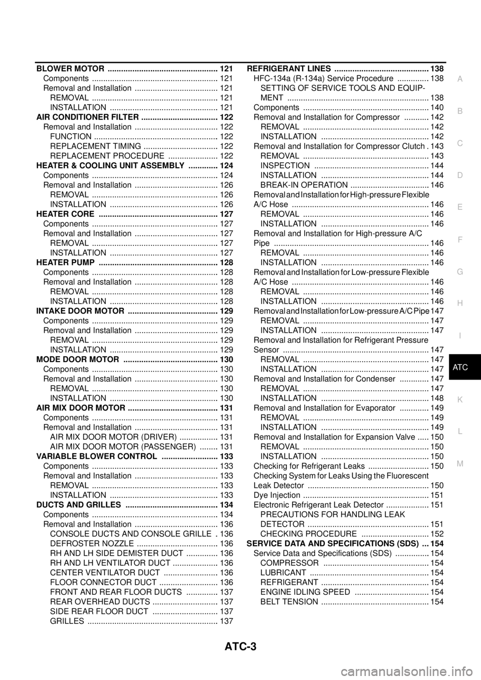
ATC-3
C
D
E
F
G
H
I
K
L
MA
B
AT C BLOWER MOTOR .................................................. 121
Components ......................................................... 121
Removal and Installation ...................................... 121
REMOVAL ......................................................... 121
INSTALLATION ................................................. 121
AIR CONDITIONER FILTER ................................... 122
Removal and Installation ...................................... 122
FUNCTION ........................................................ 122
REPLACEMENT TIMING .................................. 122
REPLACEMENT PROCEDURE ....................... 122
HEATER & COOLING UNIT ASSEMBLY .............. 124
Components ......................................................... 124
Removal and Installation ...................................... 126
REMOVAL ......................................................... 126
INSTALLATION ................................................. 126
HEATER CORE ...................................................... 127
Components ......................................................... 127
Removal and Installation ...................................... 127
REMOVAL ......................................................... 127
INSTALLATION ................................................. 127
HEATER PUMP ...................................................... 128
Components ......................................................... 128
Removal and Installation ...................................... 128
REMOVAL ......................................................... 128
INSTALLATION ................................................. 128
INTAKE DOOR MOTOR ......................................... 129
Components ......................................................... 129
Removal and Installation ...................................... 129
REMOVAL ......................................................... 129
INSTALLATION ................................................. 129
MODE DOOR MOTOR ........................................... 130
Components ......................................................... 130
Removal and Installation ...................................... 130
REMOVAL ......................................................... 130
INSTALLATION ................................................. 130
AIR MIX DOOR MOTOR ......................................... 131
Components ......................................................... 131
Removal and Installation ...................................... 131
AIR MIX DOOR MOTOR (DRIVER) .................. 131
AIR MIX DOOR MOTOR (PASSENGER) ......... 131
VARIABLE BLOWER CONTROL .......................... 133
Components ......................................................... 133
Removal and Installation ...................................... 133
REMOVAL ......................................................... 133
INSTALLATION ................................................. 133
DUCTS AND GRILLES .......................................... 134
Components ......................................................... 134
Removal and Installation ...................................... 136
CONSOLE DUCTS AND CONSOLE GRILLE .. 136
DEFROSTER NOZZLE ..................................... 136
RH AND LH SIDE DEMISTER DUCT ............... 136
RH AND LH VENTILATOR DUCT ..................... 136
CENTER VENTILATOR DUCT ......................... 136
FLOOR CONNECTOR DUCT ........................... 136
FRONT AND REAR FLOOR DUCTS ............... 137
REAR OVERHEAD DUCTS .............................. 137
SIDE REAR FLOOR DUCT .............................. 137
GRILLES ........................................................... 137REFRIGERANT LINES ...........................................138
HFC-134a (R-134a) Service Procedure ...............138
SETTING OF SERVICE TOOLS AND EQUIP-
MENT ................................................................138
Components .........................................................140
Removal and Installation for Compressor ............142
REMOVAL .........................................................142
INSTALLATION .................................................142
Removal and Installation for Compressor Clutch . 143
REMOVAL .........................................................143
INSPECTION ....................................................144
INSTALLATION .................................................144
BREAK-IN OPERATION ....................................146
Removal and Installation for High-pressure Flexible
A/C Hose ..............................................................146
REMOVAL .........................................................146
INSTALLATION .................................................146
Removal and Installation for High-pressure A/C
Pipe ......................................................................146
REMOVAL .........................................................146
INSTALLATION .................................................146
Removal and Installation for Low-pressure Flexible
A/C Hose ..............................................................146
REMOVAL .........................................................146
INSTALLATION .................................................146
Removal and Installation for Low-pressure A/C Pipe.147
REMOVAL .........................................................147
INSTALLATION .................................................147
Removal and Installation for Refrigerant Pressure
Sensor ..................................................................147
REMOVAL .........................................................147
INSTALLATION .................................................147
Removal and Installation for Condenser ..............147
REMOVAL .........................................................147
INSTALLATION .................................................148
Removal and Installation for Evaporator ..............149
REMOVAL .........................................................149
INSTALLATION .................................................149
Removal and Installation for Expansion Valve ......150
REMOVAL .........................................................150
INSTALLATION .................................................150
Checking for Refrigerant Leaks ............................150
Checking System for Leaks Using the Fluorescent
Leak Detector .......................................................150
Dye Injection .........................................................151
Electronic Refrigerant Leak Detector ....................151
PRECAUTIONS FOR HANDLING LEAK
DETECTOR .......................................................151
CHECKING PROCEDURE ...............................152
SERVICE DATA AND SPECIFICATIONS (SDS) ....154
Service Data and Specifications (SDS) ................154
COMPRESSOR ................................................154
LUBRICANT ......................................................154
REFRIGERANT .................................................154
ENGINE IDLING SPEED ..................................154
BELT TENSION .................................................154
Page 469 of 3171
DUCTS AND GRILLES
ATC-135
C
D
E
F
G
H
I
K
L
MA
B
AT C
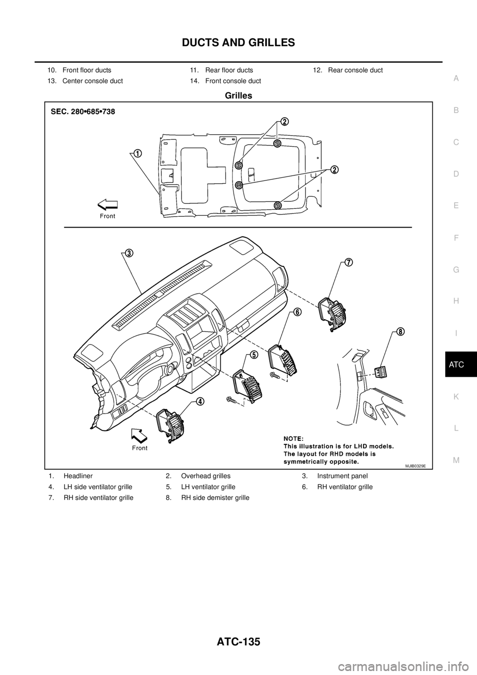
Grilles
10. Front floor ducts 11. Rear floor ducts 12. Rear console duct
13. Center console duct 14. Front console duct
MJIB0329E
1. Headliner 2. Overhead grilles 3. Instrument panel
4. LH side ventilator grille 5. LH ventilator grille 6. RH ventilator grille
7. RH side ventilator grille 8. RH side demister grille
Page 470 of 3171
ATC-136
DUCTS AND GRILLES
Removal and Installation
EJS006CK
CONSOLE DUCTS AND CONSOLE GRILLE
Removal
The center console must be removed and disassembled to remove the console ducts and the console grille.
Refer toIP-16, "
CENTER CONSOLE".
Installation
Installation is in the reverse order of removal.
DEFROSTER NOZZLE
Removal
1. Remove the instrument panel trim. Refer toIP-10, "Removal and Installation".
2. Remove the defroster nozzle.
Installation
Installation is in the reverse order of removal.
RH AND LH SIDE DEMISTER DUCT
Removal
1. Remove the instrument panel trim. Refer toIP-10, "Removal and Installation".
2. Remove the center console. Refer toIP-16, "
CENTER CONSOLE".
3. Remove the RH or LH side demister duct.
Installation
Installation is in the reverse order of removal.
RH AND LH VENTILATOR DUCT
Removal
1. Remove the instrument panel trim. Refer toIP-10, "Removal and Installation".
2. Remove the center console. Refer toIP-16, "
CENTER CONSOLE".
3. Remove the RH or LH ventilator duct.
Installation
Installation is in the reverse order of removal.
CENTER VENTILATOR DUCT
Removal
1. Remove the heater and cooling unit assembly. Refer toATC-126, "REMOVAL".
2. Remove the center console. Refer toIP-16, "
CENTER CONSOLE".
3. Remove the defroster nozzle.
4. Remove the RH and LH ventilator ducts.
5. Remove the RH and LH side demister ducts.
6. Remove the center ventilator duct.
Installation
Installation is in the reverse order of removal.
FLOOR CONNECTOR DUCT
Removal
1. Remove the heater and cooling unit assembly. Refer toATC-126, "REMOVAL".
2. Remove the center console. Refer toIP-16, "
CENTER CONSOLE".
3. Remove the floor connector duct.
Installation
Installation is in the reverse order of removal.
Page 471 of 3171
DUCTS AND GRILLES
ATC-137
C
D
E
F
G
H
I
K
L
MA
B
AT C
FRONT AND REAR FLOOR DUCTS
Removal
1. Remove the center console. Refer toIP-16, "CENTER CONSOLE".
2. Remove the floor carpet. Refer toEI-38, "
Removal and Installation".
3. Remove the clips and remove the front and rear floor ducts.
Installation
Installation is in the reverse order of removal.
REAR OVERHEAD DUCTS
Removal
1. Remove the rear RH interior trim panel. Refer toEI-33, "BODY SIDE TRIM".
2. Remove the headliner. Refer toEI-40, "
HEADLINING".
NOTE:
The rear headliner duct (connected to the rear upper overhead duct) is part of the headliner and is
replaced as an assembly.
3. Remove the clips and remove the rear upper and lower overhead ducts.
Installation
Installation is in the reverse order of removal.
SIDE REAR FLOOR DUCT
Removal
1. Remove the rear RH interior trim panel. Refer toEI-33, "BODY SIDE TRIM".
2. Reposition the floor carpet out of the way.
3. Remove the clips and remove the side rear floor duct.
Installation
Installation is in the reverse order of removal.
GRILLES
Removal
1. Remove the necessary interior trim panel(s) to access the grille. Refer toIP-10, "Removal and Installation"
.
NOTE:
The overhead grilles are part of the headliner. To replace the overhead grilles the headliner must be
replaced. Refer toEI-40, "
HEADLINING".
2. Remove the grille from the interior trim panel.
Installation
Installation is in the reverse order of removal.
Page 585 of 3171
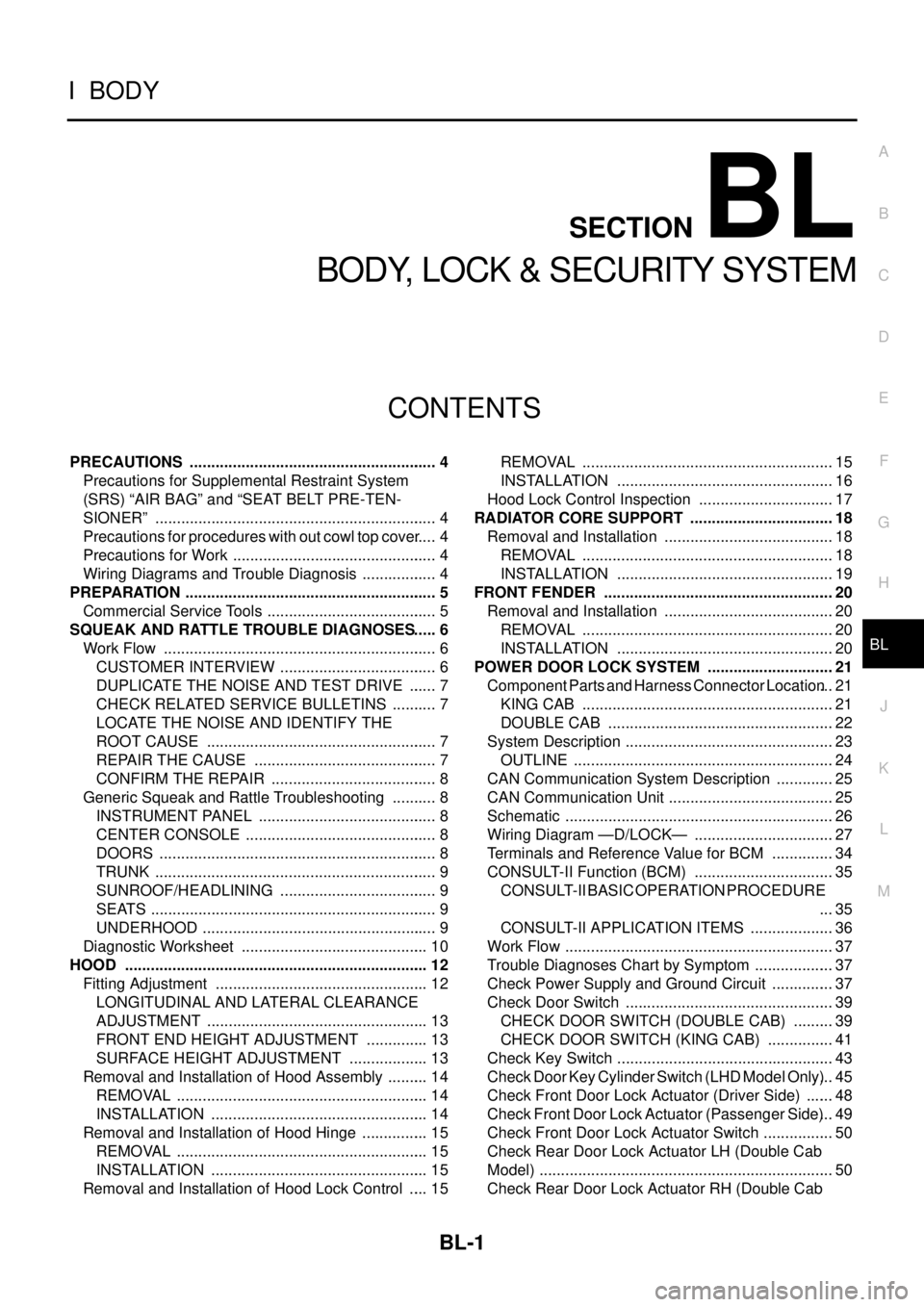
BL-1
BODY, LOCK & SECURITY SYSTEM
IBODY
CONTENTS
C
D
E
F
G
H
J
K
L
M
SECTIONBL
A
B
BL
BODY, LOCK & SECURITY SYSTEM
PRECAUTIONS .......................................................... 4
Precautions for Supplemental Restraint System
(SRS)“AIRBAG”and“SEATBELTPRE-TEN-
SIONER” .................................................................. 4
Precautions for procedures with out cowl top cover..... 4
Precautions for Work ................................................ 4
Wiring Diagrams and Trouble Diagnosis .................. 4
PREPARATION ........................................................... 5
Commercial Service Tools ........................................ 5
SQUEAK AND RATTLE TROUBLE DIAGNOSES..... 6
Work Flow ................................................................ 6
CUSTOMER INTERVIEW ..................................... 6
DUPLICATE THE NOISE AND TEST DRIVE ....... 7
CHECK RELATED SERVICE BULLETINS ........... 7
LOCATE THE NOISE AND IDENTIFY THE
ROOT CAUSE ...................................................... 7
REPAIR THE CAUSE ........................................... 7
CONFIRM THE REPAIR ....................................... 8
Generic Squeak and Rattle Troubleshooting ........... 8
INSTRUMENT PANEL .......................................... 8
CENTER CONSOLE ............................................. 8
DOORS ................................................................. 8
TRUNK .................................................................. 9
SUNROOF/HEADLINING ..................................... 9
SEATS ................................................................... 9
UNDERHOOD ....................................................... 9
Diagnostic Worksheet ............................................ 10
HOOD ....................................................................... 12
Fitting Adjustment .................................................. 12
LONGITUDINAL AND LATERAL CLEARANCE
ADJUSTMENT .................................................... 13
FRONT END HEIGHT ADJUSTMENT ............... 13
SURFACE HEIGHT ADJUSTMENT ................... 13
Removal and Installation of Hood Assembly .......... 14
REMOVAL ........................................................... 14
INSTALLATION ................................................... 14
Removal and Installation of Hood Hinge ................ 15
REMOVAL ........................................................... 15
INSTALLATION ................................................... 15
Removal and Installation of Hood Lock Control ..... 15REMOVAL ........................................................... 15
INSTALLATION ................................................... 16
Hood Lock Control Inspection ................................ 17
RADIATOR CORE SUPPORT .................................. 18
Removal and Installation ........................................ 18
REMOVAL ........................................................... 18
INSTALLATION ................................................... 19
FRONT FENDER ...................................................... 20
Removal and Installation ........................................ 20
REMOVAL ........................................................... 20
INSTALLATION ................................................... 20
POWER DOOR LOCK SYSTEM .............................. 21
Component Parts and Harness Connector Location... 21
KING CAB ........................................................... 21
DOUBLE CAB ..................................................... 22
System Description ................................................. 23
OUTLINE ............................................................. 24
CAN Communication System Description .............. 25
CAN Communication Unit ....................................... 25
Schematic ............................................................... 26
Wiring Diagram —D/LOCK— ................................. 27
Terminals and Reference Value for BCM ............... 34
CONSULT-II Function (BCM) ................................. 35
CONSULT-II BASIC OPERATION PROCEDURE
... 35
CONSULT-II APPLICATION ITEMS .................... 36
Work Flow ............................................................... 37
Trouble Diagnoses Chart by Symptom ................... 37
Check Power Supply and Ground Circuit ............... 37
Check Door Switch ................................................. 39
CHECK DOOR SWITCH (DOUBLE CAB) .......... 39
CHECK DOOR SWITCH (KING CAB) ................ 41
Check Key Switch ................................................... 43
Check Door Key Cylinder Switch (LHD Model Only)... 45
Check Front Door Lock Actuator (Driver Side) ....... 48
Check Front Door Lock Actuator (Passenger Side)... 49
Check Front Door Lock Actuator Switch ................. 50
Check Rear Door Lock Actuator LH (Double Cab
Model) ..................................................................... 50
Check Rear Door Lock Actuator RH (Double Cab
Page 592 of 3171
BL-8
SQUEAK AND RATTLE TROUBLE DIAGNOSES
FELT CLOTHTAPE
Used to insulate where movement does not occur. Ideal for instrument panel applications.
68370-4B000: 15´25 mm (0.59´0.98 in) pad/68239-13E00: 5 mm (0.20 in) wide tape roll
The following materials, not available through NISSAN Parts Department, can also be used to repair squeaks
and rattles.
UHMW(TEFLON) TAPE
Insulates where slight movement is present. Ideal for instrument panel applications.
SILICONE GREASE
Used in place of UHMW tape that will be visible or not fit.
Note: Will only last a few months.
SILICONE SPRAY
Use when grease cannot be applied.
DUCT TAPE
Use to eliminate movement.
CONFIRM THE REPAIR
Confirm that the cause of a noise is repaired by test driving the vehicle. Operate the vehicle under the same
conditions as when the noise originally occurred. Refer to the notes on the Diagnostic Worksheet.
Generic Squeak and Rattle TroubleshootingEIS00DI3
Refer to Table of Contents for specific component removal and installation information.
INSTRUMENT PANEL
Most incidents are caused by contact and movement between:
1. Cluster lid A and instrument panel
2. Acrylic lens and combination meter housing
3. Instrument panel to front pillar garnish
4. Instrument panel to windshield
5. Instrument panel mounting pins
6. Wiring harnesses behind the combination meter
7. A/C defroster duct and duct joint
These incidents can usually be located by tapping or moving the components to duplicate the noise or by
pressing on the components while driving to stop the noise. Most of these incidents can be repaired by apply-
ing felt cloth tape or silicon spray (in hard to reach areas). Urethane pads can be used to insulate wiring har-
ness.
CAUTION:
Do not use silicone spray to isolate a squeak or rattle. If you saturate the area with silicone, you will
not be able to recheck the repair.
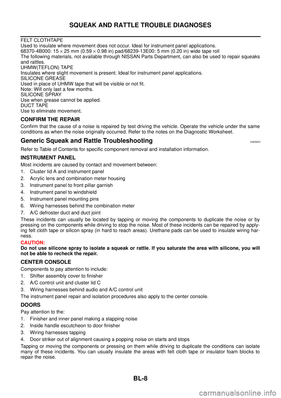
CENTER CONSOLE
Components to pay attention to include:
1. Shifter assembly cover to finisher
2. A/C control unit and cluster lid C
3. Wiring harnesses behind audio and A/C control unit
The instrument panel repair and isolation procedures also apply to the center console.
DOORS
Pay attention to the:
1. Finisher and inner panel making a slapping noise
2. Inside handle escutcheon to door finisher
3. Wiring harnesses tapping
4. Door striker out of alignment causing a popping noise on starts and stops
Tapping or moving the components or pressing on them while driving to duplicate the conditions can isolate
many of these incidents. You can usually insulate the areas with felt cloth tape or insulator foam blocks to
repair the noise.