2005 NISSAN NAVARA water pump
[x] Cancel search: water pumpPage 885 of 3171
CO-1
ENGINE COOLING SYSTEM
B ENGINE
CONTENTS
C
D
E
F
G
H
I
J
K
L
M
SECTIONCO
A
CO
ENGINE COOLING SYSTEM
PRECAUTIONS .......................................................... 2
Precautions For Liquid Gasket ................................. 2
LIQUID GASKET APPLICATION PROCEDURE..... 2
PREPARATION ........................................................... 3
Special Service Tools ............................................... 3
Commercial Service Tools ........................................ 3
OVERHEATING CAUSE ANALYSIS .......................... 4
Troubleshooting Chart .............................................. 4
COOLING SYSTEM .................................................... 6
Cooling Circuit .......................................................... 6
ENGINE COOLANT .................................................... 7
Inspection ................................................................. 7
LEVEL CHECK ..................................................... 7
CHECKING RADIATOR SYSTEM FOR LEAKS..... 7
Changing Engine Coolant ........................................ 7
DRAINING ENGINE COOLANT ........................... 8
REFILLING ENGINE COOLANT .......................... 8
FLUSHING COOLING SYSTEM ........................... 9
RADIATOR .................................................................11
Components ............................................................ 11
Removal and Installation ......................................... 11
REMOVAL ............................................................ 11
INSPECTION AFTER REMOVAL ....................... 13
INSTALLATION ................................................... 14
INSPECTION AFTER INSTALLATION ............... 14
RADIATOR (ALUMINUM TYPE) .............................. 15
Components ........................................................... 15
Disassembly and Assembly ................................... 15
PREPARATION ................................................... 15
DISASSEMBLY ................................................... 15
ASSEMBLY ......................................................... 16
INSPECTION ...................................................... 18COOLING FAN .......................................................... 19
Components (Crankshaft Driven Type) .................. 19
Removal and Installation ........................................ 19
REMOVAL ........................................................... 19
INSPECTION AFTER REMOVAL ....................... 19
INSTALLATION ................................................... 19
Removal and Installation (Motor Driven Type) (Mod-
els with A/C) ........................................................... 19
REMOVAL ........................................................... 19
INSTALLATION ................................................... 20
WATER PUMP .......................................................... 21
Components ........................................................... 21
Removal and Installation ........................................ 21
REMOVAL ........................................................... 21
INSPECTION AFTER REMOVAL ....................... 22
INSTALLATION ................................................... 22
INSPECTION AFTER INSTALLATION ................ 22
THERMOSTAT AND WATER PIPING ...................... 23
Components ........................................................... 23
Removal and Installation ........................................ 24
REMOVAL ........................................................... 24
INSPECTION AFTER REMOVAL ....................... 24
INSTALLATION ................................................... 24
INSPECTION AFTER INSTALLATION ................ 25
SERVICE DATA AND SPECIFICATIONS (SDS) ...... 26
Standard and Limit .................................................. 26
ENGINE COOLANT CAPACITY .......................... 26
THERMOSTAT .................................................... 26
RESERVOIR TANK ............................................. 26
Page 888 of 3171
CO-4
OVERHEATING CAUSE ANALYSIS
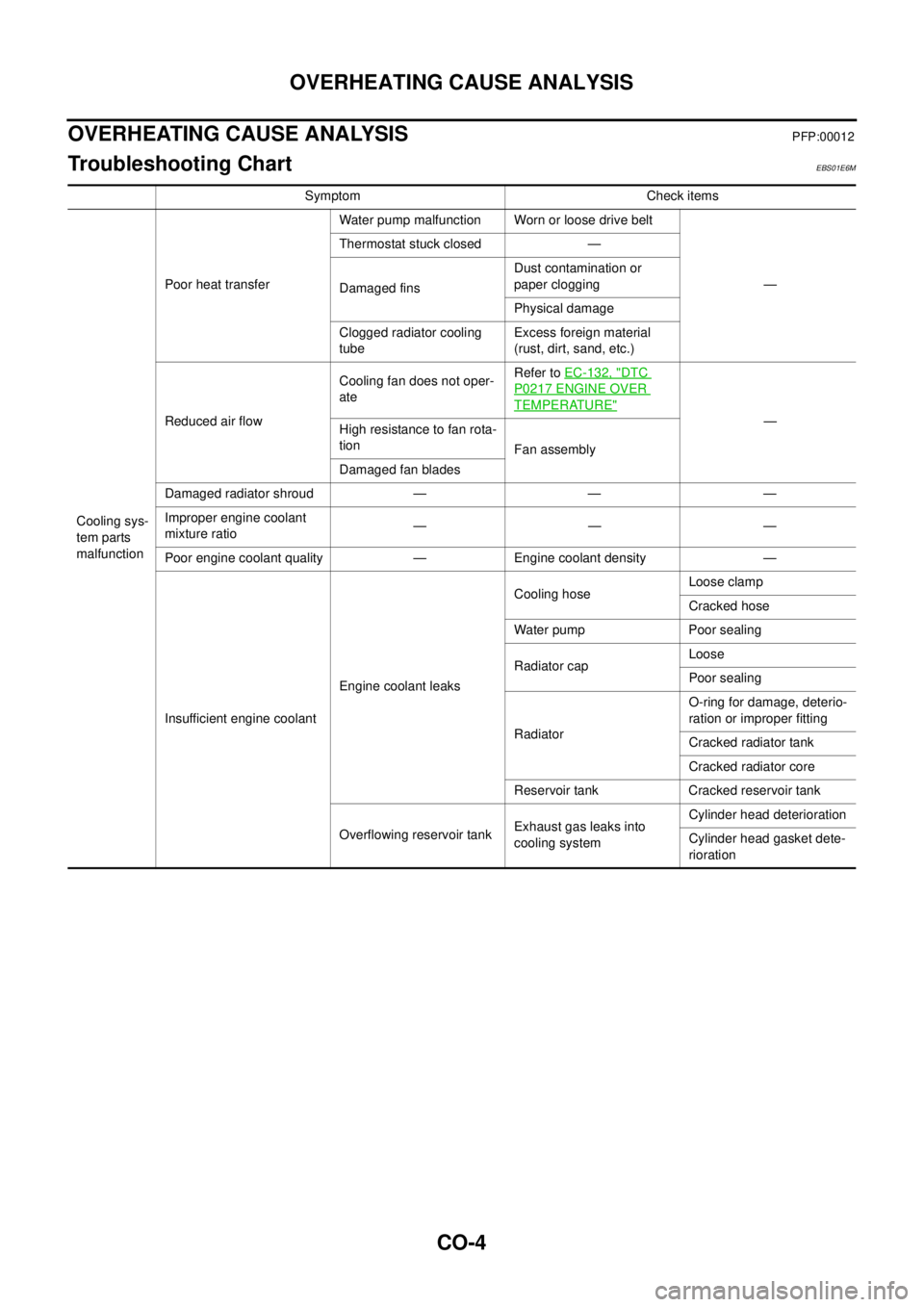
OVERHEATING CAUSE ANALYSIS
PFP:00012
Troubleshooting ChartEBS01E6M
Symptom Check items
Cooling sys-
tem parts
malfunctionPoor heat transferWater pump malfunction Worn or loose drive belt
— Thermostat stuck closed —
Damaged finsDust contamination or
paper clogging
Physical damage
Clogged radiator cooling
tubeExcess foreign material
(rust, dirt, sand, etc.)
Reduced air flowCooling fan does not oper-
ateRefer toEC-132, "
DTC
P0217 ENGINE OVER
TEMPERATURE"
—
Highresistancetofanrota-
tion
Fan assembly
Damaged fan blades
Damaged radiator shroud — — —
Improper engine coolant
mixture ratio—— —
Poor engine coolant quality — Engine coolant density —
Insufficient engine coolantEngine coolant leaksCooling hoseLoose clamp
Cracked hose
Water pump Poor sealing
Radiator capLoose
Poor sealing
RadiatorO-ring for damage, deterio-
ration or improper fitting
Cracked radiator tank
Cracked radiator core
Reservoir tank Cracked reservoir tank
Overflowing reservoir tankExhaust gas leaks into
cooling systemCylinder head deterioration
Cylinder head gasket dete-
rioration
Page 903 of 3171
COOLING FAN
CO-19
C
D
E
F
G
H
I
J
K
L
MA
CO
COOLING FANPFP:21140
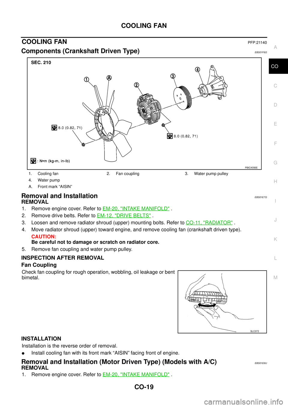
Components (Crankshaft Driven Type)EBS01F6G
Removal and InstallationEBS01E7G
REMOVAL
1. Remove engine cover. Refer toEM-20, "INTAKE MANIFOLD".
2. Remove drive belts. Refer toEM-12, "
DRIVE BELTS".
3. Loosen and remove radiator shroud (upper) mounting bolts. Refer toCO-11, "
RADIATOR".
4. Move radiator shroud (upper) toward engine, and remove cooling fan (crankshaft driven type).
CAUTION:
Be careful not to damage or scratch on radiator core.
5. Remove fan coupling and water pump pulley.
INSPECTION AFTER REMOVAL
Fan Coupling
Check fan coupling for rough operation, wobbling, oil leakage or bent
bimetal.
INSTALLATION
Installation is the reverse order of removal.
lInstall cooling fan with its front mark “AISIN” facing front of engine.
Removal and Installation (Motor Driven Type) (Models with A/C)EBS01E6U
REMOVAL
1. Remove engine cover. Refer toEM-20, "INTAKE MANIFOLD".
1. Cooling fan 2. Fan coupling 3. Water pump pulley
4. Water pump
A. Front mark “AISIN”
PBIC4056E
SLC072
Page 905 of 3171
WATER PUMP
CO-21
C
D
E
F
G
H
I
J
K
L
MA
CO
WAT E R P U MPPFP:21020
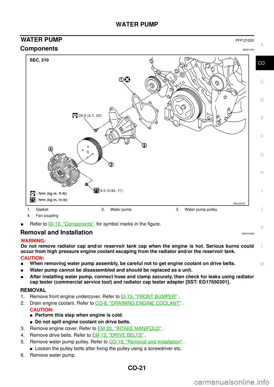
ComponentsEBS01F6K
lRefer toGI-10, "Components"for symbol marks in the figure.
Removal and InstallationEBS01E6W
WARNING:
Do not remove radiator cap and/or reservoir tank cap when the engine is hot. Serious burns could
occur from high pressure engine coolant escaping from the radiator and/or the reservoir tank.
CAUTION:
lWhen removing water pump assembly, be careful not to get engine coolant on drive belts.
lWater pump cannot be disassembled and should be replaced as a unit.
lAfter installing water pump, connect hose and clamp securely, then check for leaks using radiator
cap tester (commercial service tool) and radiator cap tester adapter [SST: EG17650301].
REMOVAL
1. Remove front engine undercover. Refer toEI-15, "FRONT BUMPER".
2. Drain engine coolant. Refer toCO-8, "
DRAINING ENGINE COOLANT".
CAUTION:
lPerform this step when engine is cold.
lDo not spill engine coolant on drive belts.
3. Remove engine cover. Refer toEM-20, "
INTAKE MANIFOLD".
4. Remove drive belts. Refer toEM-12, "
DRIVE BELTS".
5. Remove water pump pulley. Refer toCO-19, "
Removal and Installation".
lLoosen the pulley bolts after fixing the pulley using a screwdriver etc.
6. Remove water pump.
1. Gasket 2. Water pump 3. Water pump pulley
4. Fan coupling
PBIC4057E
Page 906 of 3171
CO-22
WATER PUMP
lEngine coolant will leak from cylinder block, so have a receptacle ready below.
CAUTION:
lHandle the water pump vane so that it does not contact any other parts.
lWater pump cannot be disassembled and should be replaced as a unit.
INSPECTION AFTER REMOVAL
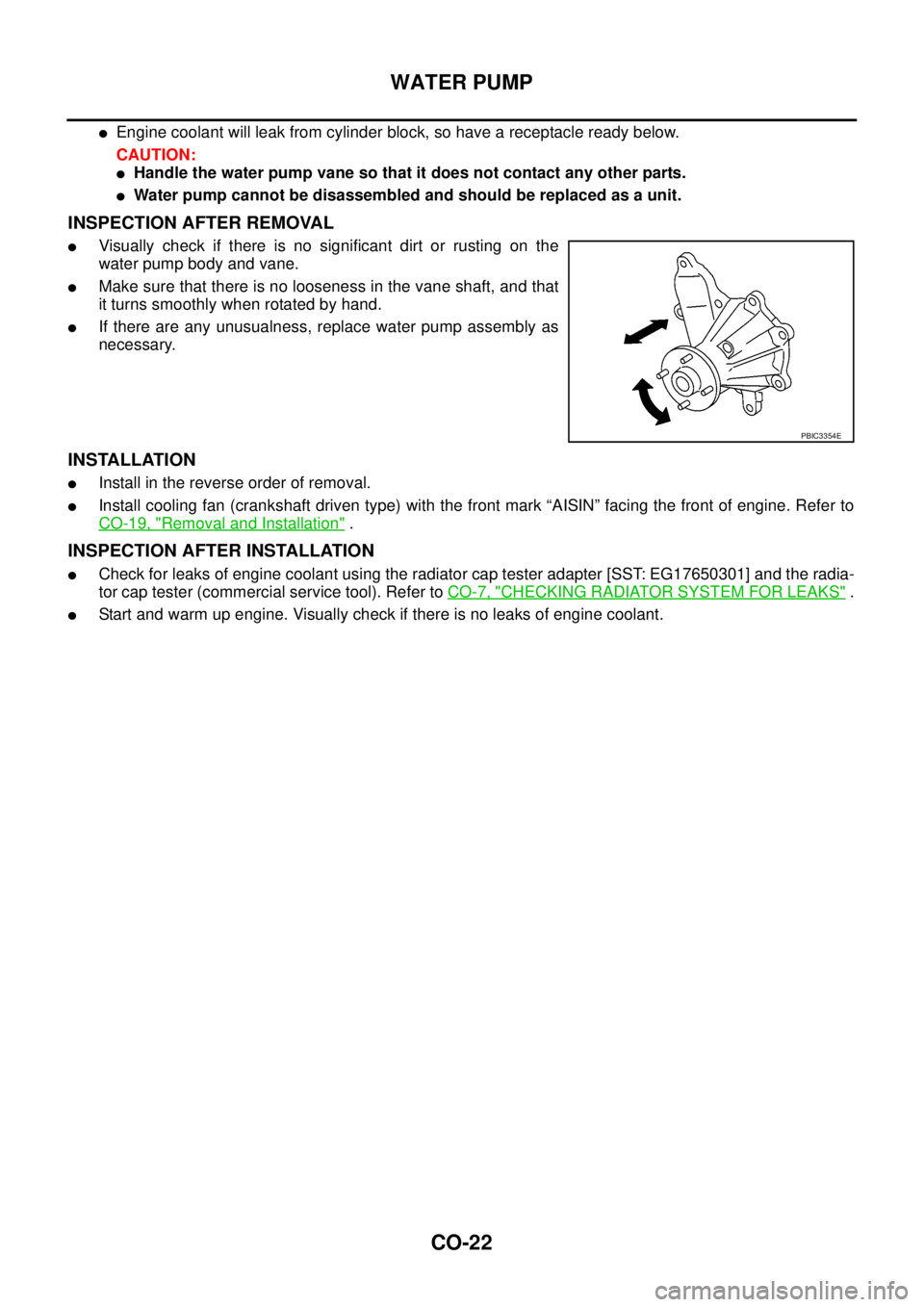
lVisually check if there is no significant dirt or rusting on the
water pump body and vane.
lMake sure that there is no looseness in the vane shaft, and that
it turns smoothly when rotated by hand.
lIf there are any unusualness, replace water pump assembly as
necessary.
INSTALLATION
lInstall in the reverse order of removal.
lInstall cooling fan (crankshaft driven type) with the front mark “AISIN” facing the front of engine. Refer to
CO-19, "
Removal and Installation".
INSPECTION AFTER INSTALLATION
lCheck for leaks of engine coolant using the radiator cap tester adapter [SST: EG17650301] and the radia-
tor cap tester (commercial service tool). Refer toCO-7, "
CHECKING RADIATOR SYSTEM FOR LEAKS".
lStart and warm up engine. Visually check if there is no leaks of engine coolant.
PBIC3354E
Page 997 of 3171
ENGINE CONTROL SYSTEM
EC-17
C
D
E
F
G
H
I
J
K
L
MA
EC
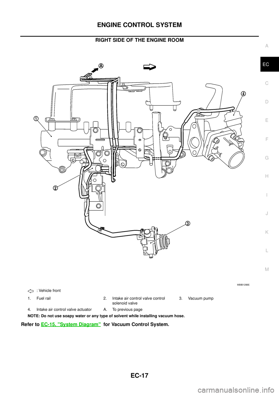
RIGHT SIDE OF THE ENGINE ROOM
Refer toEC-15, "System Diagram"for Vacuum Control System.
MBIB1288E
: Vehicle front
1. Fuel rail 2. Intake air control valve control
solenoid valve3. Vacuum pump
4. Intake air control valve actuator A. To previous page
NOTE: Do not use soapy water or any type of solvent while installing vacuum hose.
Page 1003 of 3171
BASIC SERVICE PROCEDURE
EC-23
C
D
E
F
G
H
I
J
K
L
MA
EC
BASIC SERVICE PROCEDUREPFP:00018
Fuel FilterEBS01KCK
DESCRIPTION
A water draining cock is on the lower side and a priming pump for bleeding air is on the upper side.
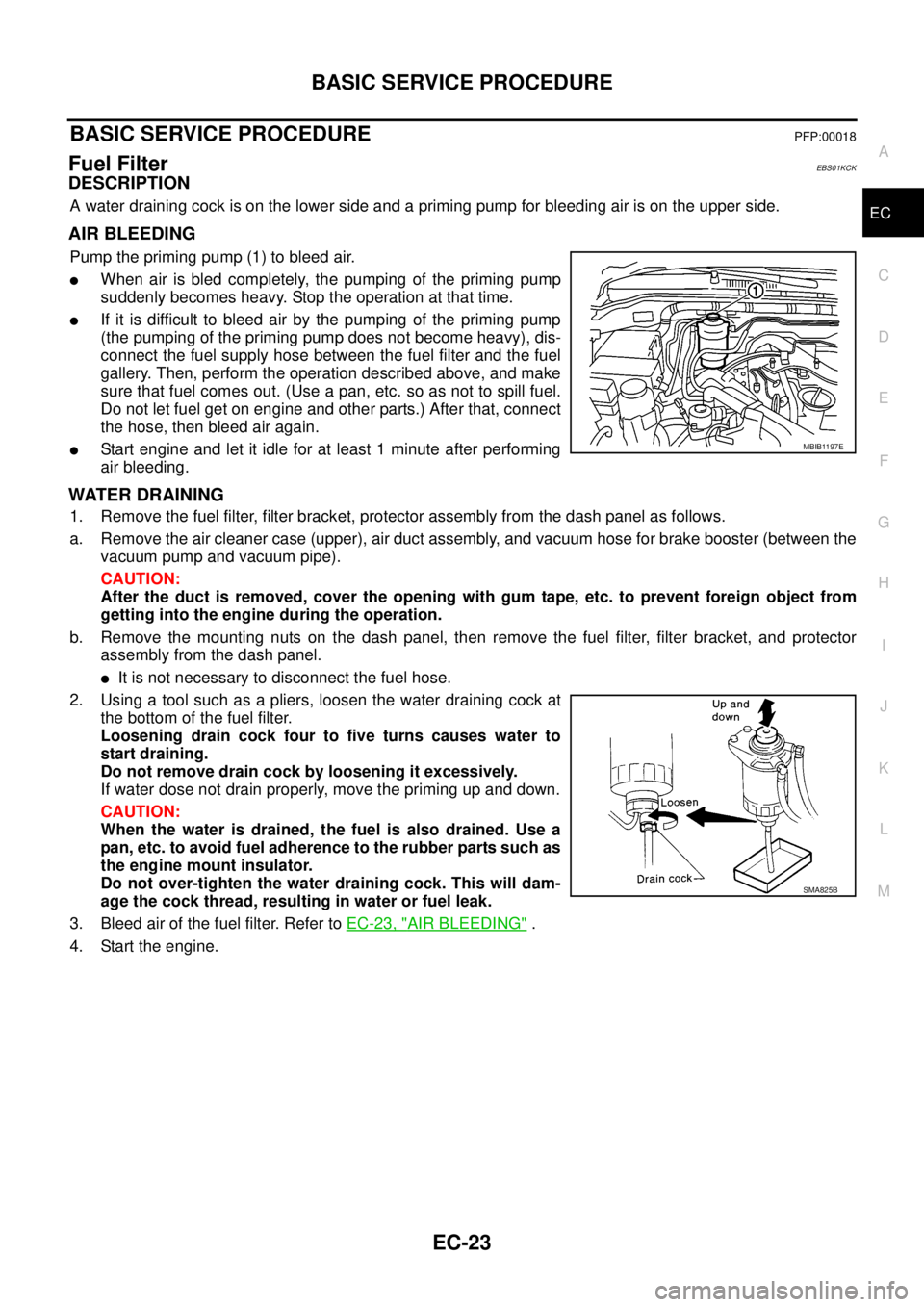
AIR BLEEDING
Pump the priming pump (1) to bleed air.
lWhen air is bled completely, the pumping of the priming pump
suddenly becomes heavy. Stop the operation at that time.
lIf it is difficult to bleed air by the pumping of the priming pump
(the pumping of the priming pump does not become heavy), dis-
connect the fuel supply hose between the fuel filter and the fuel
gallery. Then, perform the operation described above, and make
sure that fuel comes out. (Use a pan, etc. so as not to spill fuel.
Do not let fuel get on engine and other parts.) After that, connect
the hose, then bleed air again.
lStart engine and let it idle for at least 1 minute after performing
air bleeding.
WATER DRAINING
1. Remove the fuel filter, filter bracket, protector assembly from the dash panel as follows.
a. Remove the air cleaner case (upper), air duct assembly, and vacuum hose for brake booster (between the
vacuum pump and vacuum pipe).
CAUTION:
After the duct is removed, cover the opening with gum tape, etc. to prevent foreign object from
getting into the engine during the operation.
b. Remove the mounting nuts on the dash panel, then remove the fuel filter, filter bracket, and protector
assembly from the dash panel.
lIt is not necessary to disconnect the fuel hose.
2. Using a tool such as a pliers, loosen the water draining cock at
the bottom of the fuel filter.
Loosening drain cock four to five turns causes water to
start draining.
Do not remove drain cock by loosening it excessively.
If water dose not drain properly, move the priming up and down.
CAUTION:
When the water is drained, the fuel is also drained. Use a
pan, etc. to avoid fuel adherence to the rubber parts such as
the engine mount insulator.
Do not over-tighten the water draining cock. This will dam-
age the cock thread, resulting in water or fuel leak.
3. Bleed air of the fuel filter. Refer toEC-23, "
AIR BLEEDING".
4. Start the engine.
MBIB1197E
SMA825B
Page 1019 of 3171
TROUBLE DIAGNOSIS
EC-39
C
D
E
F
G
H
I
J
K
L
MA
EC
3.CHECK IDLE SPEED
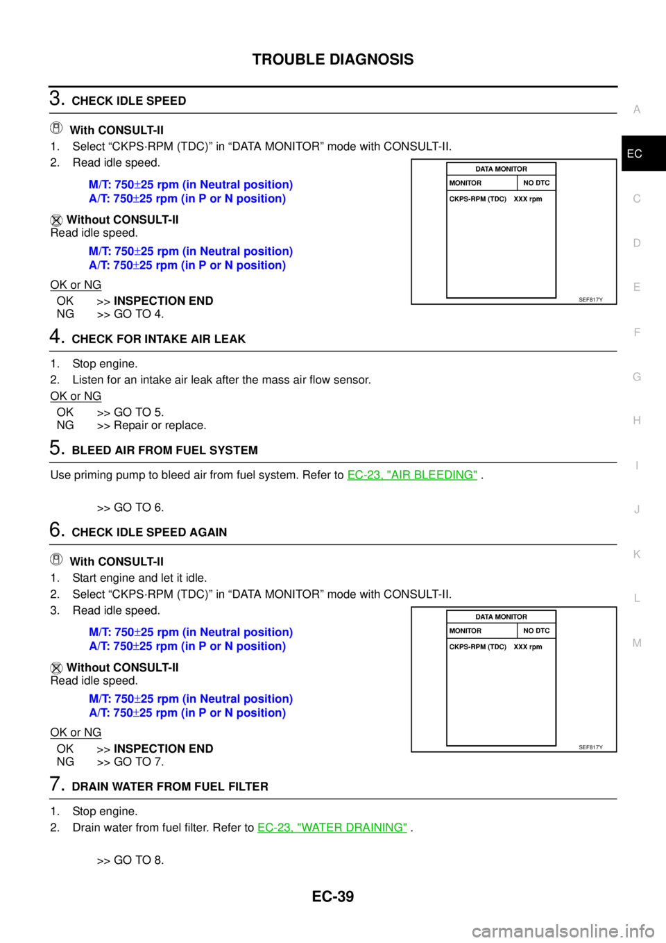
With CONSULT-II
1. Select “CKPS·RPM (TDC)” in “DATA MONITOR” mode with CONSULT-II.
2. Read idle speed.
Without CONSULT-II
Read idle speed.
OK or NG
OK >>INSPECTION END
NG >> GO TO 4.
4.CHECK FOR INTAKE AIR LEAK
1. Stop engine.
2. Listen for an intake air leak after the mass air flow sensor.
OK or NG
OK >> GO TO 5.
NG >> Repair or replace.
5.BLEED AIR FROM FUEL SYSTEM
Use priming pump to bleed air from fuel system. Refer toEC-23, "
AIR BLEEDING".
>> GO TO 6.
6.CHECK IDLE SPEED AGAIN
With CONSULT-II
1. Start engine and let it idle.
2. Select “CKPS·RPM (TDC)” in “DATA MONITOR” mode with CONSULT-II.
3. Read idle speed.
Without CONSULT-II
Read idle speed.
OK or NG
OK >>INSPECTION END
NG >> GO TO 7.
7.DRAIN WATER FROM FUEL FILTER
1. Stop engine.
2. Drain water from fuel filter. Refer toEC-23, "
WATER DRAINING".
>> GO TO 8. M/T: 750±25 rpm (in Neutral position)
A/T: 750±25 rpm (in P or N position)
M/T: 750±25 rpm (in Neutral position)
A/T: 750±25 rpm (in P or N position)
SEF817Y
M/T: 750±25 rpm (in Neutral position)
A/T: 750±25 rpm (in P or N position)
M/T: 750±25 rpm (in Neutral position)
A/T: 750±25 rpm (in P or N position)
SEF817Y