2005 NISSAN NAVARA battery replacement
[x] Cancel search: battery replacementPage 227 of 3171
ON-VEHICLE SERVICE
AT-219
D
E
F
G
H
I
J
K
L
MA
B
AT
CONTROL VALVE WITH TCM REMOVAL AND INSTALLATION
Removal
1. Disconnect the battery cable from the negative terminal.
2. Remove under cover.
3. Drain ATF through drain hole.
4. Remove control cable from A/T assembly. Refer toAT- 2 1 0 , "
COMPONENTS".
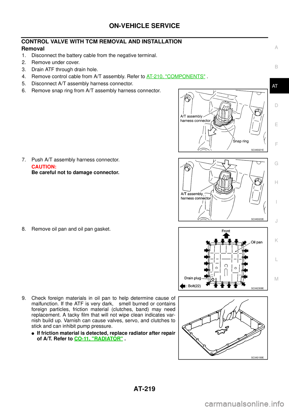
5. Disconnect A/T assembly harness connector.
6. Remove snap ring from A/T assembly harness connector.
7. Push A/T assembly harness connector.
CAUTION:
Be careful not to damage connector.
8. Remove oil pan and oil pan gasket.
9. Check foreign materials in oil pan to help determine cause of
malfunction. If the ATF is very dark, smell burned or contains
foreign particles, friction material (clutches, band) may need
replacement. A tacky film that will not wipe clean indicates var-
nish build up. Varnish can cause valves, servo, and clutches to
stick and can inhibit pump pressure.
lIf friction material is detected, replace radiator after repair
of A/T. Refer toCO-11, "
RADIATOR".
SCIA5021E
SCIA5022E
SCIA2308E
SCIA5199E
Page 235 of 3171
ON-VEHICLE SERVICE
AT-227
D
E
F
G
H
I
J
K
L
MA
B
AT
A/T FLUID TEMPERATURE SENSOR 2 REMOVAL AND INSTALLATION
Removal
1. Disconnect the battery cable from the negative terminal.
2. Remove under cover.
3. Drain ATF through drain hole.
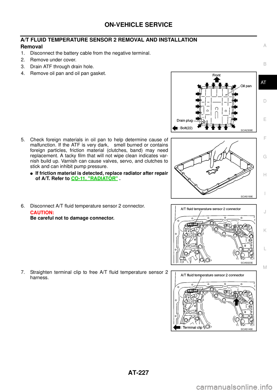
4. Remove oil pan and oil pan gasket.
5. Check foreign materials in oil pan to help determine cause of
malfunction. If the ATF is very dark, smell burned or contains
foreign particles, friction material (clutches, band) may need
replacement. A tacky film that will not wipe clean indicates var-
nish build up. Varnish can cause valves, servo, and clutches to
stick and can inhibit pump pressure.
lIf friction material is detected, replace radiator after repair
of A/T. Refer toCO-11, "
RADIATOR".
6. Disconnect A/T fluid temperature sensor 2 connector.
CAUTION:
Be careful not to damage connector.
7. Straighten terminal clip to free A/T fluid temperature sensor 2
harness.
SCIA2308E
SCIA5199E
SCIA5023E
SCIA5146E
Page 492 of 3171

AV-4
SYSTEM DESCRIPTION
SYSTEM DESCRIPTION
PFP:00000
System FunctionsEKS00Q5X
Refer to Owner's Manual for audio system operating instructions.
AUDIO
Speed Sensitive Volume (6CD Player Type)
Volume level of this system gone up and down automatically in proportion to the vehicle speed. And the con-
trol level can be selected by the customer.
NATS AUDIO LINK (WITHOUT NAVIGATION SYSTEM)
Description
The link with the NATS IMMU implies that the audio unit can basically only be operated if connected to the
matching NATS IMMU to which the audio unit was initially fitted on the production line.
Since radio operation is impossible after the link with the NATS is disrupted theft of the audio unit is basically
useless since special equipment is required to reset the audio unit.
Initialization Process for Audio Units That Are Linked to The NATS IMMU
New audio units will be delivered to the factories in the “NEW” state, i.e. ready to be linked with the vehicle's
NATS. When the audio unit in “NEW” state is first switched on at the factory, it will start up communication with
the vehicle's immobilizer control unit (IMMU) and send a code (the “audio unit Code”) to the IMMU. The IMMU
will then store this code, which is unique to each audio unit, in its (permanent) memory.
Upon receipt of the code by the IMMU, the NATS will confirm correct receipt of the audio unit code to the audio
unit. Hereafter, the audio unit will operate as normal.
During the initialization process, “NEW” is displayed on the audio unit display. Normally though, communica-
tion between audio unit and IMMU takes such a short time (300 ms) that the audio unit seems to switch on
directly without showing “NEW” on its display.
Normal Operation
Each time the audio unit is switched on afterwards, the audio unit code will be verified between the audio unit
and the NATS before the audio unit becomes operational. During the code verification process, “WAIT” is
shown on the audio unit display. Again, the communication takes such a short time (300 ms) that the audio
unit seems to switch on directly without showing “WAIT” on its display.
When The Radio Is Locked
In case of a audio unit being linked with the vehicle's NATS (immobilizer system), disconnection of the link
between the audio unit and the IMMU will cause the audio unit to switch into the lock (“SECURE”) mode in
which the audio unit is fully inoperative. Hence, repair of the audio unit is basically impossible, unless the
audio unit is reset to the “NEW” state for which special decoding equipment is required.
Clarion has provided their authorized service representatives with so called “decoder boxes” which can bring
the audio unit back to the “NEW” state, enabling the audio unit to be switched on after which repair can be per-
formed. Subsequently, when the repaired audio unit is delivered to the final user again, it will be in the “NEW”
state to enable re-linking the audio unit to the vehicle's immobilizer system. As a result of the above, repair of
the audio unit can only be done by an authorized Clarion representative (when the owner of the vehicle
requests repair and can show personal identification).
Service Procedure
Item Service procedure Description
Battery disconnection No additional action required. –
Radio needs repair Repair needs to be done by authorized
representative of radio manufacturer since
radio cannot be operated unless it is reset
to NEW state, using special decoding
equipment.–
Replacement of radio by new part No additional action required. Radio is delivered in NEW state.
Transferring radio to another vehicle/
replacement of radio by an “old” partRadio needs to be reset to NEW state by
authorized representative of radio manu-
facturer.–
Replacement of IMMU Radio needs to be reset to NEW state by
authorized representative of Clarion.After switching on the radio, it will display
“SECURE” after 1 minute.
Page 586 of 3171

BL-2
Model) ..................................................................... 51
Check RH and LH Rear Door Lock Actuator Switch... 51
Check Door Lock/Unlock Switch ............................ 52
Check Door Lock/Unlock Switch Indicator .............. 53
POWER DOOR LOCK — SUPER LOCK — ............ 55
Component Parts and Harness Connector Location... 55
KING CAB ........................................................... 55
DOUBLE CAB ..................................................... 56
System Description ................................................. 57
OUTLINE ............................................................. 58
OPERATION ........................................................ 58
CAN Communication System Description .............. 59
CAN Communication Unit ....................................... 59
Schematic ............................................................... 60
Wiring Diagram —D/LOCK— ................................. 61
Terminals and Reference Value for BCM ................ 69
CONSULT-II Function (BCM) .................................. 70
CONSULT-II BASIC OPERATION PROCEDURE
... 70
CONSULT-II APPLICATION ITEMS .................... 71
Work Flow ............................................................... 72
Trouble Diagnoses Chart by Symptom ................... 72
Check Power Supply and Ground Circuit ............... 73
Check Door Switch ................................................. 74
CHECK DOOR SWITCH (DOUBLE CAB) .......... 74
CHECK DOOR SWITCH (KING CAB) ................ 76
Check Key Switch ................................................... 78
Check Front Door Lock Actuator (Driver Side) ....... 80
Check Front Door Lock Actuator (Passenger Side)... 81
Check Front Door Lock Actuator Switch ................. 81
Check Rear Door Lock Actuator LH (Double Cab
Models) ................................................................... 82
Check Rear Door Lock Actuator RH (Double Cab
Models) ................................................................... 82
Check RH and LH Rear Door Lock Actuator Switch
(Double Cab Models) .............................................. 83
Check Super Lock Actuator (Driver Side) ............... 83
Check Super Lock Actuator (Passenger Side) ....... 84
Check Super Lock Actuator (Rear LH) ................... 84
Check Super Lock Actuator (Rear RH) .................. 85
Check Door Lock/Unlock Switch ............................ 86
Check Door Lock/Unlock Switch Indicator .............. 87
MULTI-REMOTE CONTROL SYSTEM ..................... 89
Component Parts and Harness Connector Location... 89
KING CAB ........................................................... 89
DOUBLE CAB ..................................................... 90
System Description ................................................. 91
INPUTS ............................................................... 91
OPERATING PROCEDURE ................................ 91
CAN Communication System Description .............. 92
Wiring Diagram — MULTI — For LHD Models ....... 93
Wiring Diagram — MULTI — For RHD Models ...... 97
Terminals and Reference Value for BCM ..............101
CONSULT-II Function (BCM) ................................102
CONSULT-II Inspection Procedure .......................102
“MULTI REMOTE ENT” .....................................102
CONSULT-II Application Items .............................103
“MULTI REMOTE ENT” .....................................103
Trouble Diagnosis Procedure ...............................104Trouble Diagnosis Chart by Symptom ..................105
Check Keyfob Battery and Function .....................106
Check ACC Switch ................................................107
Check Door Switch ...............................................108
CHECK DOOR SWITCH (DOUBLE CAB) .........108
CHECK DOOR SWITCH (KING CAB) ...............110
Check Key Switch .................................................113
Check Hazard Function ........................................114
Check Map Lamp and Ignition Keyhole Illumination
Function ................................................................114
ID Code Entry Procedure ......................................115
KEYFOB ID SET UP ..........................................115
CONSULT-II INSPECTION PROCEDURE ........115
Remote Controller Battery Replacement ..............116
DOOR ......................................................................117
Fitting Adjustment (King Cab) ...............................117
FRONT DOOR ...................................................118
REAR DOOR .....................................................118
STRIKER ADJUSTMENT ..................................118
Fitting Adjustment (Double Cab) ...........................119
FRONT DOOR ...................................................120
REAR DOOR .....................................................120
STRIKER ADJUSTMENT ..................................120
Removal and Installation of Front Door ................120
REMOVAL ..........................................................120
INSTALLATION ..................................................121
Removal and Installation of Rear Door (King Cab).121
REMOVAL ..........................................................121
INSTALLATION ..................................................122
Removal and Installation of Rear Door (Double Cab)
.123
REMOVAL ..........................................................123
INSTALLATION ..................................................123
Removal and Installation of Door Weather-strip
(King Cab) .............................................................124
REMOVAL ..........................................................124
INSTALLATION ..................................................124
Removal and Installation of Door Weather-strip
(Double Cab) .........................................................125
REMOVAL ..........................................................125
INSTALLATION ..................................................125
FRONT DOOR LOCK ..............................................126
Removal and Installation .......................................126
REMOVAL ..........................................................126
INSTALLATION ..................................................129
REAR DOOR LOCK ................................................130
Removal and Installation of Rear Door Lock (King
Cab) ......................................................................130
REMOVAL ..........................................................130
INSTALLATION ..................................................131
Removal and Installation of Rear Door Lock (Double
Cab) ......................................................................132
REMOVAL ..........................................................132
INSTALLATION ..................................................134
TAIL GATE ...............................................................135
Component Parts Location ...................................135
FUEL FILLER LID OPENER ...................................136
Removal and Installation of Fuel Filler Lid ............136
REMOVAL ..........................................................136
Page 689 of 3171
MULTI-REMOTE CONTROL SYSTEM
BL-105
C
D
E
F
G
H
J
K
L
MA
B
BL
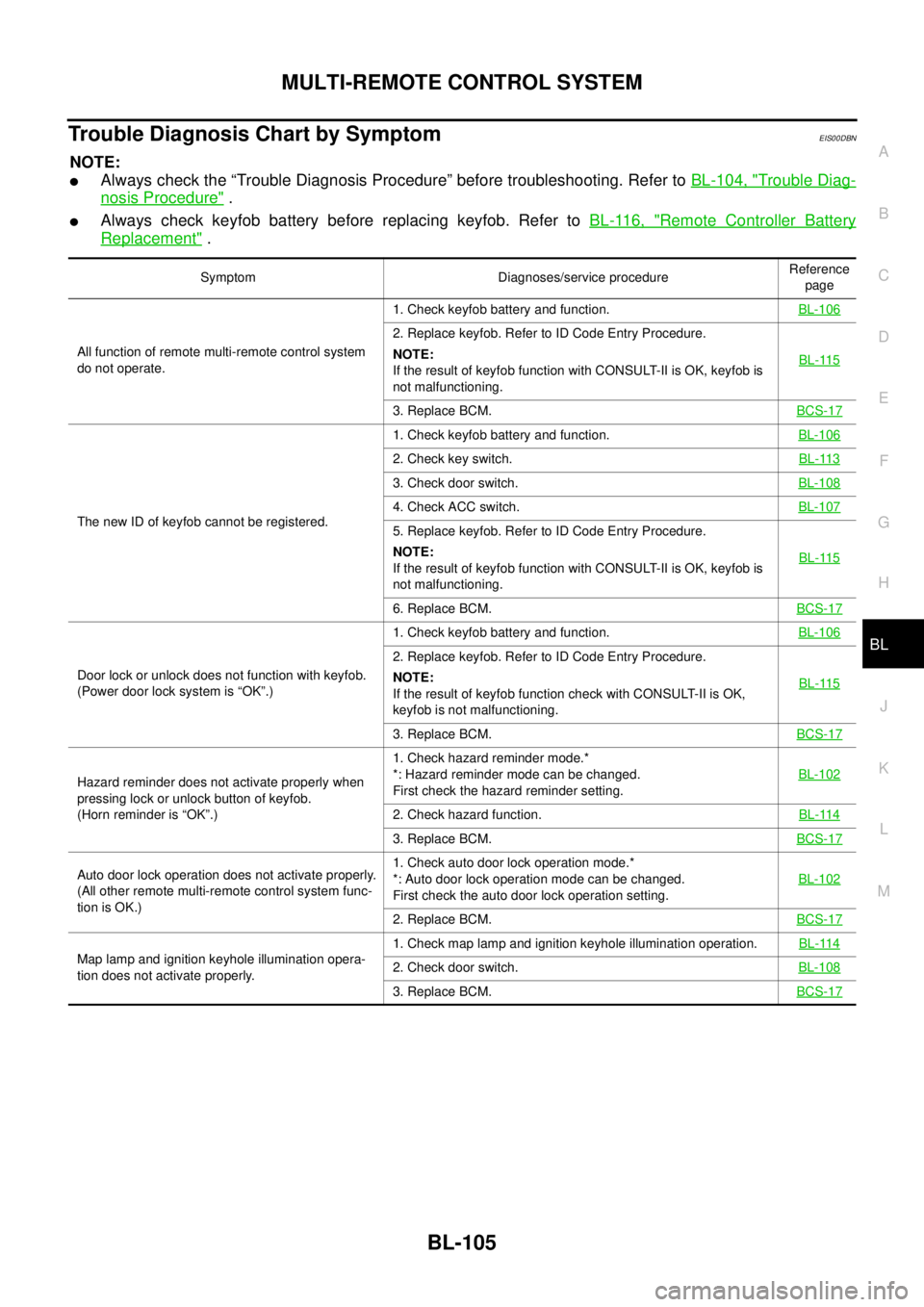
Trouble Diagnosis Chart by SymptomEIS00DBN
NOTE:
lAlways check the “Trouble Diagnosis Procedure” before troubleshooting. Refer toBL-104, "Trouble Diag-
nosis Procedure".
lAlways check keyfob battery before replacing keyfob. Refer toBL-116, "Remote Controller Battery
Replacement".
Symptom Diagnoses/service procedureReference
page
All function of remote multi-remote control system
do not operate.1. Check keyfob battery and function.BL-106
2. Replace keyfob. Refer to ID Code Entry Procedure.
NOTE:
If the result of keyfob function with CONSULT-II is OK, keyfob is
not malfunctioning.BL-115
3. Replace BCM.BCS-17
The new ID of keyfob cannot be registered.1. Check keyfob battery and function.BL-106
2. Check key switch.BL-113
3. Check door switch.BL-108
4. Check ACC switch.BL-107
5. Replace keyfob. Refer to ID Code Entry Procedure.
NOTE:
If the result of keyfob function with CONSULT-II is OK, keyfob is
not malfunctioning.BL-115
6. Replace BCM.BCS-17
Door lock or unlock does not function with keyfob.
(Power door lock system is “OK”.)1. Check keyfob battery and function.BL-106
2. Replace keyfob. Refer to ID Code Entry Procedure.
NOTE:
If the result of keyfob function check with CONSULT-II is OK,
keyfob is not malfunctioning.BL-115
3. Replace BCM.BCS-17
Hazard reminder does not activate properly when
pressing lock or unlock button of keyfob.
(Horn reminder is “OK”.)1. Check hazard reminder mode.*
*: Hazard reminder mode can be changed.
First check the hazard reminder setting.BL-102
2. Check hazard function.BL-114
3. Replace BCM.BCS-17
Auto door lock operation does not activate properly.
(All other remote multi-remote control system func-
tion is OK.)1. Check auto door lock operation mode.*
*: Auto door lock operation mode can be changed.
First check the auto door lock operation setting.BL-102
2. Replace BCM.BCS-17
Map lamp and ignition keyhole illumination opera-
tion does not activate properly.1. Check map lamp and ignition keyhole illumination operation.BL-1142. Check door switch.BL-108
3. Replace BCM.BCS-17
Page 690 of 3171

BL-106
MULTI-REMOTE CONTROL SYSTEM
Check Keyfob Battery and Function
EIS00DBO
1.CHECK KEYFOB BATTERY
1. Remove keyfob battery. Refer toBL-116, "
Remote Controller Battery Replacement".
2. Measure voltage between battery positive and negative termi-
nals, (+) and (-).
NOTE:
Keyfob does not function if battery is not set correctly.
OK or NG
OK >> GO TO 2.
NG >> Replace battery.
2.CHECK KEYFOB FUNCTION
With CONSULT-II
Check keyfob function in “DATA MONITOR” mode with CONSULT-II. When pushing each button of keyfob, the
corresponding monitor item should be turned as follows.
OK or NG
OK >> Keyfob is OK.
NG >> Replace keyfob.Voltage : 2.5 – 3.0V
SEL237W
Condition Monitor item
Pushing LOCK KEYLESS LOCK : ON
Pushing UNLOCK KEYLESS UNLOCK : ON
Press and hold UNLOCKRKE KEEP UNLK* : ON
*: Press and hold the unlock button for 3
seconds.
Pushing LOCK and UNLOCK at the
same timeRKE LCK-UNLOCK : ON
PIIA6468E
Page 700 of 3171
BL-116
MULTI-REMOTE CONTROL SYSTEM
7. Select “NATS V.5.0”.
If “NATS V5.0” is not indicated, go toGI-50, "
CONSULT-II Data
Link Connector (DLC) Circuit".
8. Perform each diagnostic test mode according to each service
procedure.
For further information, see the CONSULT-II Operation Manual
NATS.
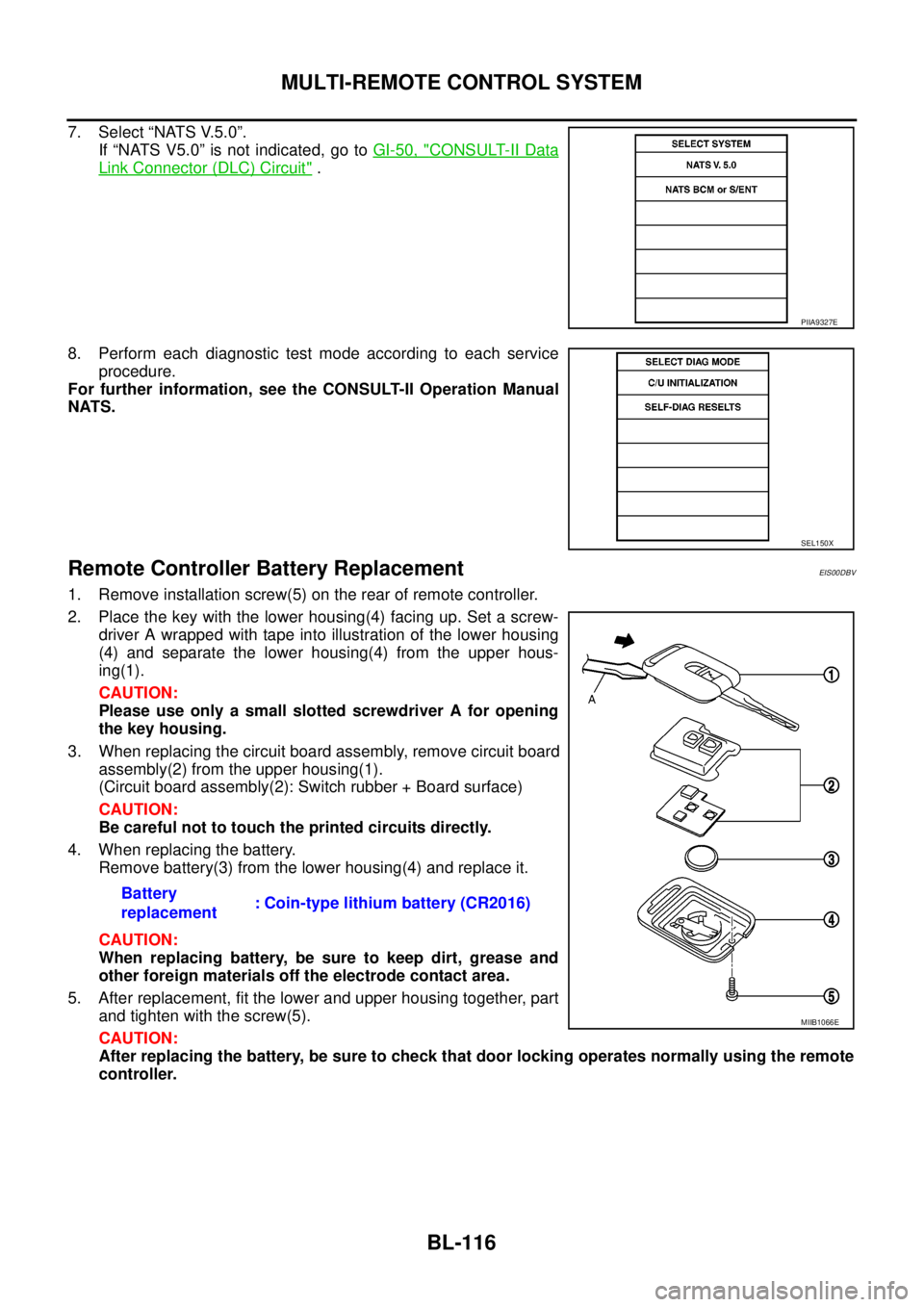
Remote Controller Battery ReplacementEIS00DBV
1. Remove installation screw(5) on the rear of remote controller.
2. Place the key with the lower housing(4) facing up. Set a screw-
driver A wrapped with tape into illustration of the lower housing
(4) and separate the lower housing(4) from the upper hous-
ing(1).
CAUTION:
Please use only a small slotted screwdriver A for opening
the key housing.
3. When replacing the circuit board assembly, remove circuit board
assembly(2) from the upper housing(1).
(Circuit board assembly(2): Switch rubber + Board surface)
CAUTION:
Be careful not to touch the printed circuits directly.
4. When replacing the battery.
Remove battery(3) from the lower housing(4) and replace it.
CAUTION:
When replacing battery, be sure to keep dirt, grease and
other foreign materials off the electrode contact area.
5. After replacement, fit the lower and upper housing together, part
and tighten with the screw(5).
CAUTION:
After replacing the battery, be sure to check that door locking operates normally using the remote
controller.
PIIA9327E
SEL150X
Battery
replacement: Coin-type lithium battery (CR2016)
MIIB1066E
Page 1623 of 3171
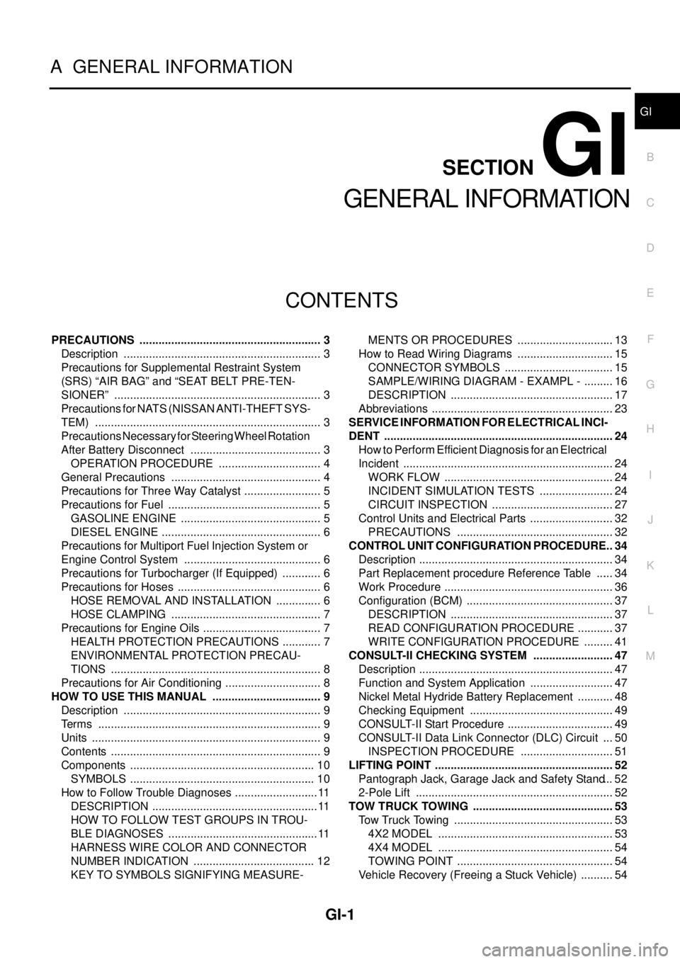
GI-1
GENERAL INFORMATION
A GENERAL INFORMATION
CONTENTS
C
D
E
F
G
H
I
J
K
L
MB
GI
SECTIONGI
GENERAL INFORMATION
PRECAUTIONS .......................................................... 3
Description ............................................................... 3
Precautions for Supplemental Restraint System
(SRS)“AIRBAG”and“SEATBELTPRE-TEN-
SIONER” .................................................................. 3
Precautions for NATS (NISSAN ANTI-THEFT SYS-
TEM) ........................................................................ 3
Precautions Necessary for Steering Wheel Rotation
After Battery Disconnect .......................................... 3
OPERATION PROCEDURE ................................. 4
General Precautions ................................................ 4
Precautions for Three Way Catalyst ......................... 5
Precautions for Fuel ................................................. 5
GASOLINE ENGINE ............................................. 5
DIESEL ENGINE ................................................... 6
Precautions for Multiport Fuel Injection System or
Engine Control System ............................................ 6
Precautions for Turbocharger (If Equipped) ............. 6
Precautions for Hoses .............................................. 6
HOSE REMOVAL AND INSTALLATION ............... 6
HOSE CLAMPING ................................................ 7
Precautions for Engine Oils ...................................... 7
HEALTH PROTECTION PRECAUTIONS ............. 7
ENVIRONMENTAL PROTECTION PRECAU-
TIONS ................................................................... 8
Precautions for Air Conditioning ............................... 8
HOW TO USE THIS MANUAL ................................... 9
Description ............................................................... 9
Terms ....................................................................... 9
Units ......................................................................... 9
Contents ................................................................... 9
Components ........................................................... 10
SYMBOLS ........................................................... 10
How to Follow Trouble Diagnoses ........................... 11
DESCRIPTION ..................................................... 11
HOW TO FOLLOW TEST GROUPS IN TROU-
BLE DIAGNOSES ................................................ 11
HARNESS WIRE COLOR AND CONNECTOR
NUMBER INDICATION ....................................... 12
KEY TO SYMBOLS SIGNIFYING MEASURE-MENTS OR PROCEDURES ............................... 13
How to Read Wiring Diagrams ............................... 15
CONNECTOR SYMBOLS ................................... 15
SAMPLE/WIRING DIAGRAM - EXAMPL - .......... 16
DESCRIPTION .................................................... 17
Abbreviations .......................................................... 23
SERVICE INFORMATION FOR ELECTRICAL INCI-
DENT ......................................................................... 24
How to Perform Efficient Diagnosis for an Electrical
Incident ................................................................... 24
WORK FLOW ...................................................... 24
INCIDENT SIMULATION TESTS ........................ 24
CIRCUIT INSPECTION ....................................... 27
Control Units and Electrical Parts ........................... 32
PRECAUTIONS .................................................. 32
CONTROL UNIT CONFIGURATION PROCEDURE... 34
Description .............................................................. 34
Part Replacement procedure Reference Table ...... 34
Work Procedure ...................................................... 36
Configuration (BCM) ............................................... 37
DESCRIPTION .................................................... 37
READ CONFIGURATION PROCEDURE ............ 37
WRITE CONFIGURATION PROCEDURE .......... 41
CONSULT-II CHECKING SYSTEM .......................... 47
Description .............................................................. 47
Function and System Application ........................... 47
Nickel Metal Hydride Battery Replacement ............ 48
Checking Equipment .............................................. 49
CONSULT-II Start Procedure .................................. 49
CONSULT-II Data Link Connector (DLC) Circuit .... 50
INSPECTION PROCEDURE .............................. 51
LIFTING POINT ......................................................... 52
Pantograph Jack, Garage Jack and Safety Stand... 52
2-Pole Lift ............................................................... 52
TOW TRUCK TOWING ............................................. 53
Tow Truck Towing ................................................... 53
4X2 MODEL ........................................................ 53
4X4 MODEL ........................................................ 54
TOWING POINT .................................................. 54
Vehicle Recovery (Freeing a Stuck Vehicle) ........... 54