2005 NISSAN NAVARA alternator
[x] Cancel search: alternatorPage 476 of 3171
ATC-142
REFRIGERANT LINES
Removal and Installation for Compressor
EJS006CN
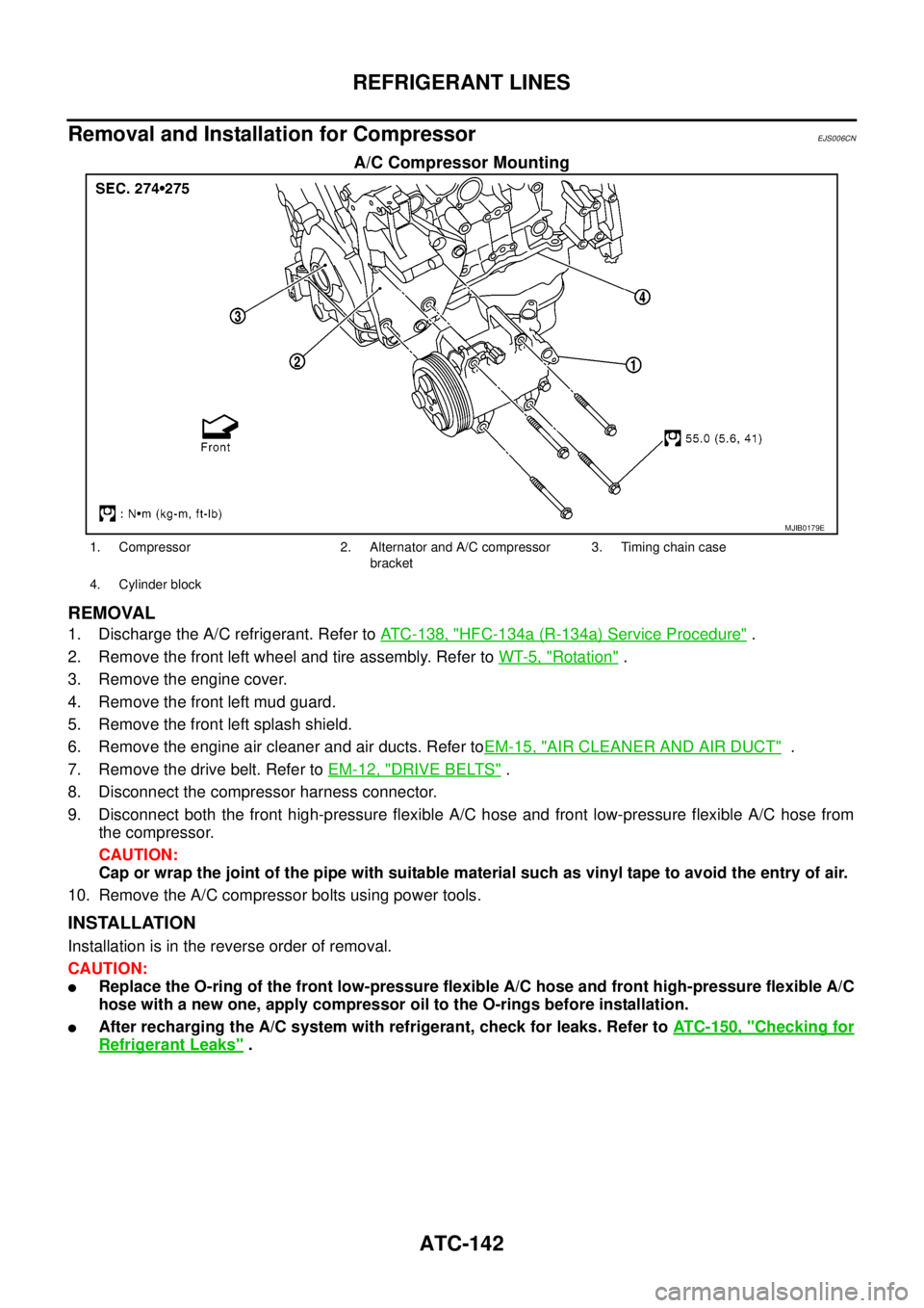
A/C Compressor Mounting
REMOVAL
1. Discharge the A/C refrigerant. Refer toATC-138, "HFC-134a (R-134a) Service Procedure".
2. Remove the front left wheel and tire assembly. Refer toWT-5, "
Rotation".
3. Remove the engine cover.
4. Remove the front left mud guard.
5. Remove the front left splash shield.
6. Remove the engine air cleaner and air ducts. Refer toEM-15, "
AIR CLEANER AND AIR DUCT".
7. Remove the drive belt. Refer toEM-12, "
DRIVE BELTS".
8. Disconnect the compressor harness connector.
9. Disconnect both the front high-pressure flexible A/C hose and front low-pressure flexible A/C hose from
the compressor.
CAUTION:
Cap or wrap the joint of the pipe with suitable material such as vinyl tape to avoid the entry of air.
10. Remove the A/C compressor bolts using power tools.
INSTALLATION
Installation is in the reverse order of removal.
CAUTION:
lReplace the O-ring of the front low-pressure flexible A/C hose and front high-pressure flexible A/C
hose with a new one, apply compressor oil to the O-rings before installation.
lAfter recharging the A/C system with refrigerant, check for leaks. Refer toATC-150, "Checking for
Refrigerant Leaks".
MJIB0179E
1. Compressor 2. Alternator and A/C compressor
bracket3. Timing chain case
4. Cylinder block
Page 845 of 3171
![NISSAN NAVARA 2005 Repair Workshop Manual TROUBLE DIAGNOSIS
BRC-23
[ABS]
C
D
E
G
H
I
J
K
L
MA
B
BRC
For Fast and Accurate DiagnosisEFS005TX
PRECAUTIONS FOR DIAGNOSIS
lBefore performing diagnosis, always read precautions. Refer toBRC-17, "CONS NISSAN NAVARA 2005 Repair Workshop Manual TROUBLE DIAGNOSIS
BRC-23
[ABS]
C
D
E
G
H
I
J
K
L
MA
B
BRC
For Fast and Accurate DiagnosisEFS005TX
PRECAUTIONS FOR DIAGNOSIS
lBefore performing diagnosis, always read precautions. Refer toBRC-17, "CONS](/manual-img/5/57362/w960_57362-844.png)
TROUBLE DIAGNOSIS
BRC-23
[ABS]
C
D
E
G
H
I
J
K
L
MA
B
BRC
For Fast and Accurate DiagnosisEFS005TX
PRECAUTIONS FOR DIAGNOSIS
lBefore performing diagnosis, always read precautions. Refer toBRC-17, "CONSULT- II Functions".
lAfter diagnosis is finished, be sure to erase memory. Refer toBRC-18, "ERASE MEMORY".
lWhen checking continuity and voltage between units, be sure to check for disconnection, looseness,
bend, or collapse of connector terminals. If any malfunction is found, repair or replace connector termi-
nals.
lFor intermittent symptoms, possible cause is malfunction in harness, harness connector, or terminals.
Move harness, harness connector, and terminals to check for poor connections.
lIf a circuit tester is used for check, be careful not to forcibly extend any connector terminal.
lABS system electrically controls brake operation and engine output. Following symptoms may be caused
by normal operations:
Basic InspectionEFS005TY
BASIC INSPECTION 1 BRAKE FLUID LEVEL, LEAKS, AND BRAKE PADS
1. Check fluid level in the brake reservoir tank. If fluid level is low, refill brake fluid.
2. Check brake tube and around ABS actuator and electric unit (control unit) for leaks. If leakage or seepage
is found, check the following items.
lIf ABS actuator and electric unit (control unit) connection is loose, tighten brake tube to the specified
torque and re-conduct the leak inspection to make sure there are no leakage.
lIf there is damage to the connection flare nut or ABS actuator and electric unit (control unit) screw,
replace the damaged part and re-conduct the leak inspection to make sure there are no leakage.
lIf there is leakage or seepage at any location other than ABS actuator and electric unit (control unit)
connection, wipe away leakage or seepage with clean cloth. Then inspect again and confirm than there
is on leakage.
lIf there is leakage from ABS actuator and electric unit (control unit), wipe away leakage or seepage with
clean cloth. Then inspect again. If there is leakage or seepage, replace ABS actuator and electric unit
(control unit).
CAUTION:
ABS actuator and electric unit (control unit) body cannot be disassembled.
3. Check brake pad degree of wear. Refer toBR-24, "
PAD WEAR INSPECTION"in “Front Disc Brake” and
BR-32, "
Lining Thickness Inspection"in “Rear Drum Brake”.
BASIC INSPECTION 2 POWER SYSTEM TERMINAL LOOSENESS AND BATTERY INSPECTION
Make sure battery positive cable, negative cable and ground connection are not loose. In addition, check the
battery voltage to make sure it has not dropped and alternator is normal.
Symptom Symptom description Result
Motor operation noiseThis is noise of motor inside ABS actuator and electric unit (control unit). Slight
noise may occur during ABS operation.
Normal
Just after engine starts, motor operating noise may be heard. This is a normal
status of the system operation check.
System operation check noiseWhen engine starts, slight “click” noise may be heard from engine compart-
ment. This is normal and is part of system operation check.Normal
ABS operation
(Longer stopping distance)When driving on roads with a low coefficient of friction, such as snowy roads
or gravel roads, the stopping distance is sometimes longer for vehicles
equipped with ABS. Therefore, when driving on such roads, drive at a suffi-
ciently reduced speed to be safe.Normal
Page 1127 of 3171
DTC P0234 TC SYSTEM
EC-147
C
D
E
F
G
H
I
J
K
L
MA
EC
DTCP0234TCSYSTEMPFP:14411
DescriptionEBS01KG1
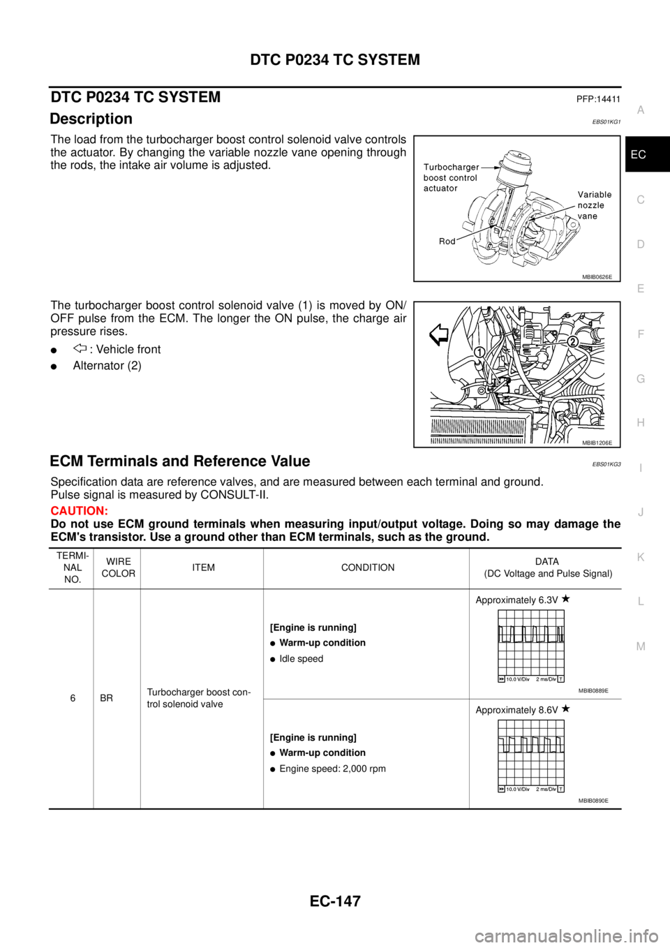
The load from the turbocharger boost control solenoid valve controls
the actuator. By changing the variable nozzle vane opening through
the rods, the intake air volume is adjusted.
The turbocharger boost control solenoid valve (1) is moved by ON/
OFF pulse from the ECM. The longer the ON pulse, the charge air
pressure rises.
l: Vehicle front
lAlternator (2)
ECM Terminals and Reference ValueEBS01KG3
Specification data are reference valves, and are measured between each terminal and ground.
Pulse signal is measured by CONSULT-II.
CAUTION:
Do not use ECM ground terminals when measuring input/output voltage. Doing so may damage the
ECM's transistor. Use a ground other than ECM terminals, such as the ground.
MBIB0626E
MBIB1206E
TERMI-
NAL
NO.WIRE
COLORITEM CONDITIONDATA
(DC Voltage and Pulse Signal)
6BRTurbocharger boost con-
trol solenoid valve[Engine is running]
lWarm-up condition
lIdle speedApproximately 6.3V
[Engine is running]
lWarm-up condition
lEngine speed: 2,000 rpmApproximately 8.6V
MBIB0889E
MBIB0890E
Page 1130 of 3171
EC-150
DTC P0234 TC SYSTEM
Diagnostic Procedure
EBS01KG7
1.CHECK VACUUM SOURCE
1. Turn ignition switch OFF.
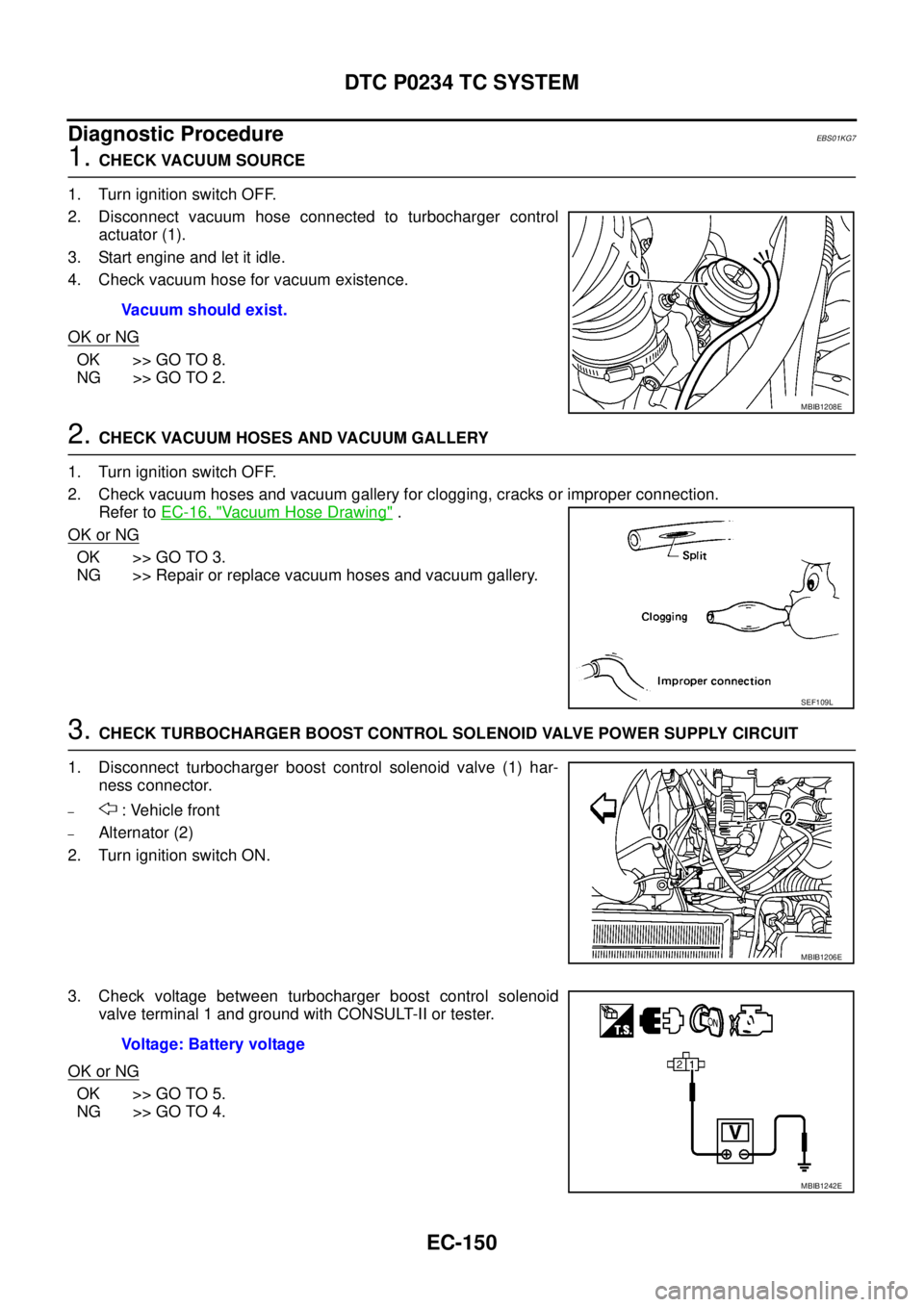
2. Disconnect vacuum hose connected to turbocharger control
actuator (1).
3. Start engine and let it idle.
4. Check vacuum hose for vacuum existence.
OK or NG
OK >> GO TO 8.
NG >> GO TO 2.
2.CHECK VACUUM HOSES AND VACUUM GALLERY
1. Turn ignition switch OFF.
2. Check vacuum hoses and vacuum gallery for clogging, cracks or improper connection.
Refer toEC-16, "
Vacuum Hose Drawing".
OK or NG
OK >> GO TO 3.
NG >> Repair or replace vacuum hoses and vacuum gallery.
3.CHECK TURBOCHARGER BOOST CONTROL SOLENOID VALVE POWER SUPPLY CIRCUIT
1. Disconnect turbocharger boost control solenoid valve (1) har-
ness connector.
–: Vehicle front
–Alternator (2)
2. Turn ignition switch ON.
3. Check voltage between turbocharger boost control solenoid
valve terminal 1 and ground with CONSULT-II or tester.
OK or NG
OK >> GO TO 5.
NG >> GO TO 4.Vacuum should exist.
MBIB1208E
SEF109L
MBIB1206E
Voltage: Battery voltage
MBIB1242E
Page 1132 of 3171
EC-152
DTC P0234 TC SYSTEM
9.CHECK TURBOCHARGER BOOST SENSOR
Refer toEC-158, "
Component Inspection".
OK or NG
OK >> GO TO 10.
NG >> Replace turbocharger boost sensor.
10.CHECK INTERMITTENT INCIDENT
Refer toEC-70, "
TROUBLE DIAGNOSIS FOR INTERMITTENT INCIDENT".
>>INSPECTION END
Component InspectionEBS01KG8
TURBOCHARGER BOOST CONTROL SOLENOID VALVE
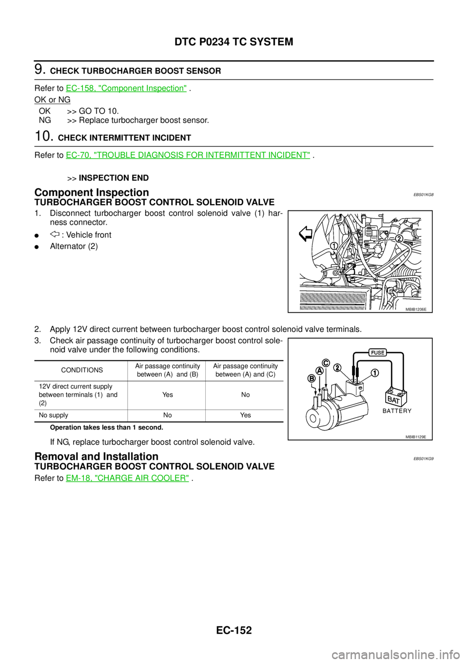
1. Disconnect turbocharger boost control solenoid valve (1) har-
ness connector.
l: Vehicle front
lAlternator (2)
2. Apply 12V direct current between turbocharger boost control solenoid valve terminals.
3. Check air passage continuity of turbocharger boost control sole-
noid valve under the following conditions.
Operation takes less than 1 second.
If NG, replace turbocharger boost control solenoid valve.
Removal and InstallationEBS01KG9
TURBOCHARGER BOOST CONTROL SOLENOID VALVE
Refer toEM-18, "CHARGE AIR COOLER".
MBIB1206E
CONDITIONSAir passage continuity
between (A) and (B)Air passage continuity
between (A) and (C)
12V direct current supply
between terminals (1) and
(2)Ye s N o
No supply No Yes
MBIB1129E
Page 1183 of 3171
DTC P0563 BATTERY VOLTAGE
EC-203
C
D
E
F
G
H
I
J
K
L
MA
EC
DTC P0563 BATTERY VOLTAGEPFP:24410
On Board Diagnosis LogicEBS01KI1
The MI will not light up for this self-diagnosis.
DTC Confirmation ProcedureEBS01KI2
NOTE:
If DTC Confirmation Procedure has been previously conducted, always turn ignition switch OFF and wait at
least 10 seconds before conducting the next test.
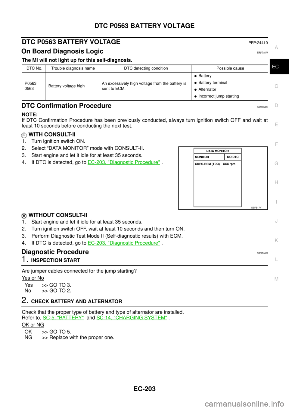
WITH CONSULT-II
1. Turn ignition switch ON.
2. Select “DATA MONITOR” mode with CONSULT-II.
3. Start engine and let it idle for at least 35 seconds.
4. If DTC is detected, go toEC-203, "
Diagnostic Procedure".
WITHOUT CONSULT-II
1. Start engine and let it idle for at least 35 seconds.
2. Turn ignition switch OFF, wait at least 10 seconds and then turn ON.
3. Perform Diagnostic Test Mode II (Self-diagnostic results) with ECM.
4. If DTC is detected, go toEC-203, "
Diagnostic Procedure".
Diagnostic ProcedureEBS01KI3
1.INSPECTION START
Are jumper cables connected for the jump starting?
Ye s o r N o
Ye s > > G O T O 3 .
No >> GO TO 2.
2.CHECK BATTERY AND ALTERNATOR
Check that the proper type of battery and type of alternator are installed.
Refer to,SC-5, "
BATTERY"andSC-14, "CHARGING SYSTEM".
OK or NG
OK >> GO TO 5.
NG >> Replace with the proper one.
DTC No. Trouble diagnosis name DTC detecting condition Possible cause
P0563
0563Battery voltage highAn excessively high voltage from the battery is
sent to ECM.
lBattery
lBattery terminal
lAlternator
lIncorrect jump starting
SEF817Y
Page 1289 of 3171
TC BOOST CONTROL SOLENOID VALVE
EC-309
C
D
E
F
G
H
I
J
K
L
MA
EC
TC BOOST CONTROL SOLENOID VALVEPFP:14956
DescriptionEBS01KLY
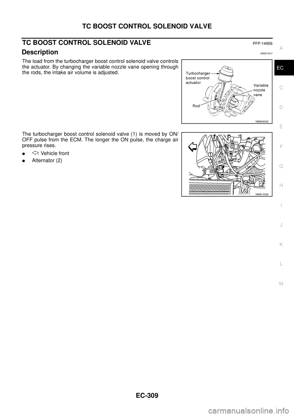
The load from the turbocharger boost control solenoid valve controls
the actuator. By changing the variable nozzle vane opening through
the rods, the intake air volume is adjusted.
The turbocharger boost control solenoid valve (1) is moved by ON/
OFF pulse from the ECM. The longer the ON pulse, the charge air
pressure rises.
l: Vehicle front
lAlternator (2)
MBIB0626E
MBIB1206E
Page 1292 of 3171
EC-312
TC BOOST CONTROL SOLENOID VALVE
Diagnostic Procedure
EBS01KM2
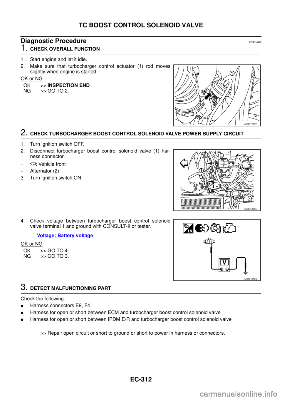
1.CHECK OVERALL FUNCTION
1. Start engine and let it idle.
2. Make sure that turbocharger control actuator (1) rod moves
slightly when engine is started.
OK or NG
OK >>INSPECTION END
NG >> GO TO 2.
2.CHECK TURBOCHARGER BOOST CONTROL SOLENOID VALVE POWER SUPPLY CIRCUIT
1. Turn ignition switch OFF.
2. Disconnect turbocharger boost control solenoid valve (1) har-
ness connector.
–: Vehicle front
–Alternator (2)
3. Turn ignition switch ON.
4. Check voltage between turbocharger boost control solenoid
valve terminal 1 and ground with CONSULT-II or tester.
OK or NG
OK >> GO TO 4.
NG >> GO TO 3.
3.DETECT MALFUNCTIONING PART
Check the following.
lHarness connectors E9, F4
lHarness for open or short between ECM and turbocharger boost control solenoid valve
lHarness for open or short between IPDM E/R and turbocharger boost control solenoid valve
>> Repair open circuit or short to ground or short to power in harness or connectors.
MBIB1207E
MBIB1206E
Voltage: Battery voltage
MBIB1242E