2005 NISSAN NAVARA battery location
[x] Cancel search: battery locationPage 553 of 3171

TROUBLE DIAGNOSIS
AV-65
C
D
E
F
G
H
I
J
L
MA
B
AV
Example of Symptoms Not MalfunctionEKS00Q6T
BASIC OPERATION
NOTE:
Locations stored in the Address Book and other memory functions may be lost if the vehicle's battery is disconnected or becomes dis-
charged. If this occurs, service the vehicle's battery as necessary and re-enter the information in the Address Book.
VEHICLE ICON
Symptom Possible cause Possible solution
No image is displayed.The brightness is at the lowest setting. Adjust the brightness of the display.
The display is turned off.
Press and hold to turn on the display.
No voice guidance is available.
The volume is too high or too low.The volume is not set correctly, or it is turned off. Adjust the volume of voice guidance.
Volume guidance is not provided for narrow streets
(roads displayed in gray).This is not a malfunction.
No map is displayed on the screen.The map DVD-ROM is not inserted, or it is inserted
upside down.Insert the map DVD-ROM correctly.
A screen other than map screen is displayed. Press “MAP”.
Thescreenistoodim.
The movement is slow.The temperature in the interior of the vehicle is low.Wait until the interior of the vehicle has
warmed up.
Some pixels in the display are
darker or brighter than others.This condition is an inherent characteristic of liquid
crystal displays.This is not a malfunction.
Some menu items cannot be
selected.Some menu items become unavailable while the
vehicle is driven.Park the vehicle in a safe location, and
then operate the navigation system.
Symptom Possible cause Possible solution
Names of roads and locations dif-
fer between Plan view and Bird-
view™.This is because the quantity of the displayed infor-
mation is reduced so that the screen does not
become too crowded. There is also a chance that
names of the roads or locations may be displayed
multiple times, and the names appearing on the a
screen may be different because of a processing
procedure.This is not a malfunction.
The vehicle icon is not displayed in
the correct position.The vehicle was transported after the ignition switch
was turned off, for example, by a ferry or car trans-
porter.Drive the vehicle for a while on a road
whereGPScanbereceived.
The position and direction of the vehicle may be
incorrect depending on the driving environments and
the levels of positioning accuracy of the navigation
system.This is not a malfunction. Drive the vehi-
cle for a while to automatically correct the
position and direction of the vehicle icon.
Whenthevehicleistravellingona
new road, the vehicle icon is
located on another road nearby.Because the new road is not stored in the map data,
the system automatically places the vehicle ion on
the nearest road available.Updated road information will be included
in the next version of the map DVD-ROM.
The screen does not switch to the
night screen even after turning on
the headlights.The daytime screen was set the last time the head-
lights were turned on.Set the screen to the night screen mode
using when turning on the headlights.
The map does not scroll even
when the vehicle is moving.The current location map screen is not displayed. Press “MAP”.
The vehicle icon is not displayed. The current location map screen is not displayed. Press “MAP”.
The GPS indicator on the screen
remains gray.GPS signals cannot be received depending on the
vehicle location, such as in a parking garage, on a
road that has numerous tall buildings, etc.Drive on an open, straight road for a
while.
GPS signals cannot be received because objects
are placed on the rear parcel shelf.Remove the objects from the rear parcel
shelf.
A sufficient amount of GPS satellites are not avail-
able.Wait for the satellites to move locations
available for navigation system.
Page 586 of 3171

BL-2
Model) ..................................................................... 51
Check RH and LH Rear Door Lock Actuator Switch... 51
Check Door Lock/Unlock Switch ............................ 52
Check Door Lock/Unlock Switch Indicator .............. 53
POWER DOOR LOCK — SUPER LOCK — ............ 55
Component Parts and Harness Connector Location... 55
KING CAB ........................................................... 55
DOUBLE CAB ..................................................... 56
System Description ................................................. 57
OUTLINE ............................................................. 58
OPERATION ........................................................ 58
CAN Communication System Description .............. 59
CAN Communication Unit ....................................... 59
Schematic ............................................................... 60
Wiring Diagram —D/LOCK— ................................. 61
Terminals and Reference Value for BCM ................ 69
CONSULT-II Function (BCM) .................................. 70
CONSULT-II BASIC OPERATION PROCEDURE
... 70
CONSULT-II APPLICATION ITEMS .................... 71
Work Flow ............................................................... 72
Trouble Diagnoses Chart by Symptom ................... 72
Check Power Supply and Ground Circuit ............... 73
Check Door Switch ................................................. 74
CHECK DOOR SWITCH (DOUBLE CAB) .......... 74
CHECK DOOR SWITCH (KING CAB) ................ 76
Check Key Switch ................................................... 78
Check Front Door Lock Actuator (Driver Side) ....... 80
Check Front Door Lock Actuator (Passenger Side)... 81
Check Front Door Lock Actuator Switch ................. 81
Check Rear Door Lock Actuator LH (Double Cab
Models) ................................................................... 82
Check Rear Door Lock Actuator RH (Double Cab
Models) ................................................................... 82
Check RH and LH Rear Door Lock Actuator Switch
(Double Cab Models) .............................................. 83
Check Super Lock Actuator (Driver Side) ............... 83
Check Super Lock Actuator (Passenger Side) ....... 84
Check Super Lock Actuator (Rear LH) ................... 84
Check Super Lock Actuator (Rear RH) .................. 85
Check Door Lock/Unlock Switch ............................ 86
Check Door Lock/Unlock Switch Indicator .............. 87
MULTI-REMOTE CONTROL SYSTEM ..................... 89
Component Parts and Harness Connector Location... 89
KING CAB ........................................................... 89
DOUBLE CAB ..................................................... 90
System Description ................................................. 91
INPUTS ............................................................... 91
OPERATING PROCEDURE ................................ 91
CAN Communication System Description .............. 92
Wiring Diagram — MULTI — For LHD Models ....... 93
Wiring Diagram — MULTI — For RHD Models ...... 97
Terminals and Reference Value for BCM ..............101
CONSULT-II Function (BCM) ................................102
CONSULT-II Inspection Procedure .......................102
“MULTI REMOTE ENT” .....................................102
CONSULT-II Application Items .............................103
“MULTI REMOTE ENT” .....................................103
Trouble Diagnosis Procedure ...............................104Trouble Diagnosis Chart by Symptom ..................105
Check Keyfob Battery and Function .....................106
Check ACC Switch ................................................107
Check Door Switch ...............................................108
CHECK DOOR SWITCH (DOUBLE CAB) .........108
CHECK DOOR SWITCH (KING CAB) ...............110
Check Key Switch .................................................113
Check Hazard Function ........................................114
Check Map Lamp and Ignition Keyhole Illumination
Function ................................................................114
ID Code Entry Procedure ......................................115
KEYFOB ID SET UP ..........................................115
CONSULT-II INSPECTION PROCEDURE ........115
Remote Controller Battery Replacement ..............116
DOOR ......................................................................117
Fitting Adjustment (King Cab) ...............................117
FRONT DOOR ...................................................118
REAR DOOR .....................................................118
STRIKER ADJUSTMENT ..................................118
Fitting Adjustment (Double Cab) ...........................119
FRONT DOOR ...................................................120
REAR DOOR .....................................................120
STRIKER ADJUSTMENT ..................................120
Removal and Installation of Front Door ................120
REMOVAL ..........................................................120
INSTALLATION ..................................................121
Removal and Installation of Rear Door (King Cab).121
REMOVAL ..........................................................121
INSTALLATION ..................................................122
Removal and Installation of Rear Door (Double Cab)
.123
REMOVAL ..........................................................123
INSTALLATION ..................................................123
Removal and Installation of Door Weather-strip
(King Cab) .............................................................124
REMOVAL ..........................................................124
INSTALLATION ..................................................124
Removal and Installation of Door Weather-strip
(Double Cab) .........................................................125
REMOVAL ..........................................................125
INSTALLATION ..................................................125
FRONT DOOR LOCK ..............................................126
Removal and Installation .......................................126
REMOVAL ..........................................................126
INSTALLATION ..................................................129
REAR DOOR LOCK ................................................130
Removal and Installation of Rear Door Lock (King
Cab) ......................................................................130
REMOVAL ..........................................................130
INSTALLATION ..................................................131
Removal and Installation of Rear Door Lock (Double
Cab) ......................................................................132
REMOVAL ..........................................................132
INSTALLATION ..................................................134
TAIL GATE ...............................................................135
Component Parts Location ...................................135
FUEL FILLER LID OPENER ...................................136
Removal and Installation of Fuel Filler Lid ............136
REMOVAL ..........................................................136
Page 657 of 3171

POWER DOOR LOCK — SUPER LOCK —
BL-73
C
D
E
F
G
H
J
K
L
MA
B
BL
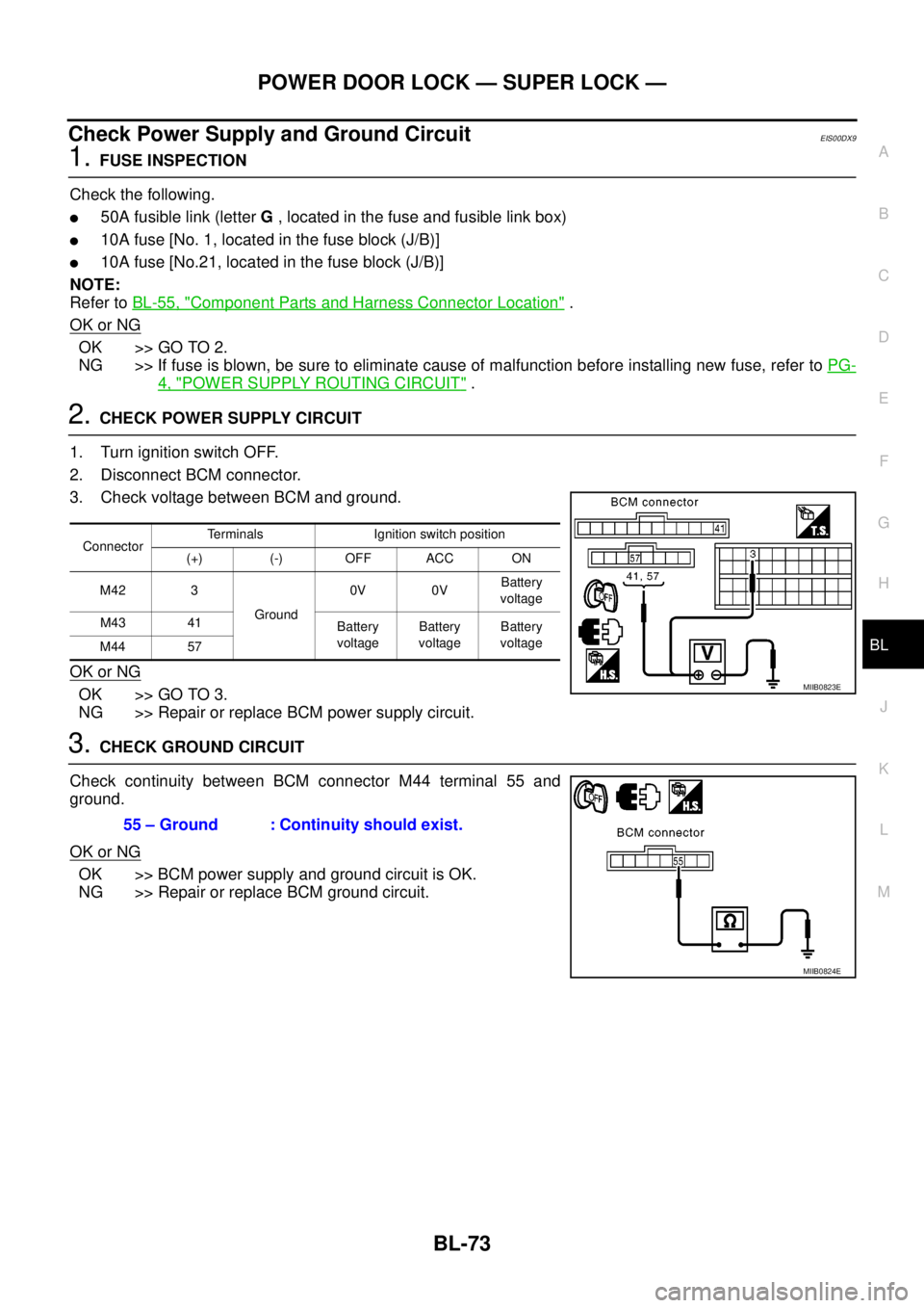
Check Power Supply and Ground CircuitEIS00DX9
1.FUSE INSPECTION
Check the following.
l50A fusible link (letterG, located in the fuse and fusible link box)
l10A fuse [No. 1, located in the fuse block (J/B)]
l10A fuse [No.21, located in the fuse block (J/B)]
NOTE:
Refer toBL-55, "
Component Parts and Harness Connector Location".
OK or NG
OK >> GO TO 2.
NG >> If fuse is blown, be sure to eliminate cause of malfunction before installing new fuse, refer toPG-
4, "POWER SUPPLY ROUTING CIRCUIT".
2.CHECK POWER SUPPLY CIRCUIT
1. Turn ignition switch OFF.
2. Disconnect BCM connector.
3. Check voltage between BCM and ground.
OK or NG
OK >> GO TO 3.
NG >> Repair or replace BCM power supply circuit.
3.CHECK GROUND CIRCUIT
Check continuity between BCM connector M44 terminal 55 and
ground.
OK or NG
OK >> BCM power supply and ground circuit is OK.
NG >> Repair or replace BCM ground circuit.
ConnectorTerminals Ignition switch position
(+) (-) OFF ACC ON
M42 3
Ground0V 0VBattery
voltage
M43 41
Battery
voltageBattery
voltageBattery
voltage
M44 57
MIIB0823E
55 – Ground : Continuity should exist.
MIIB0824E
Page 823 of 3171

BRC-1
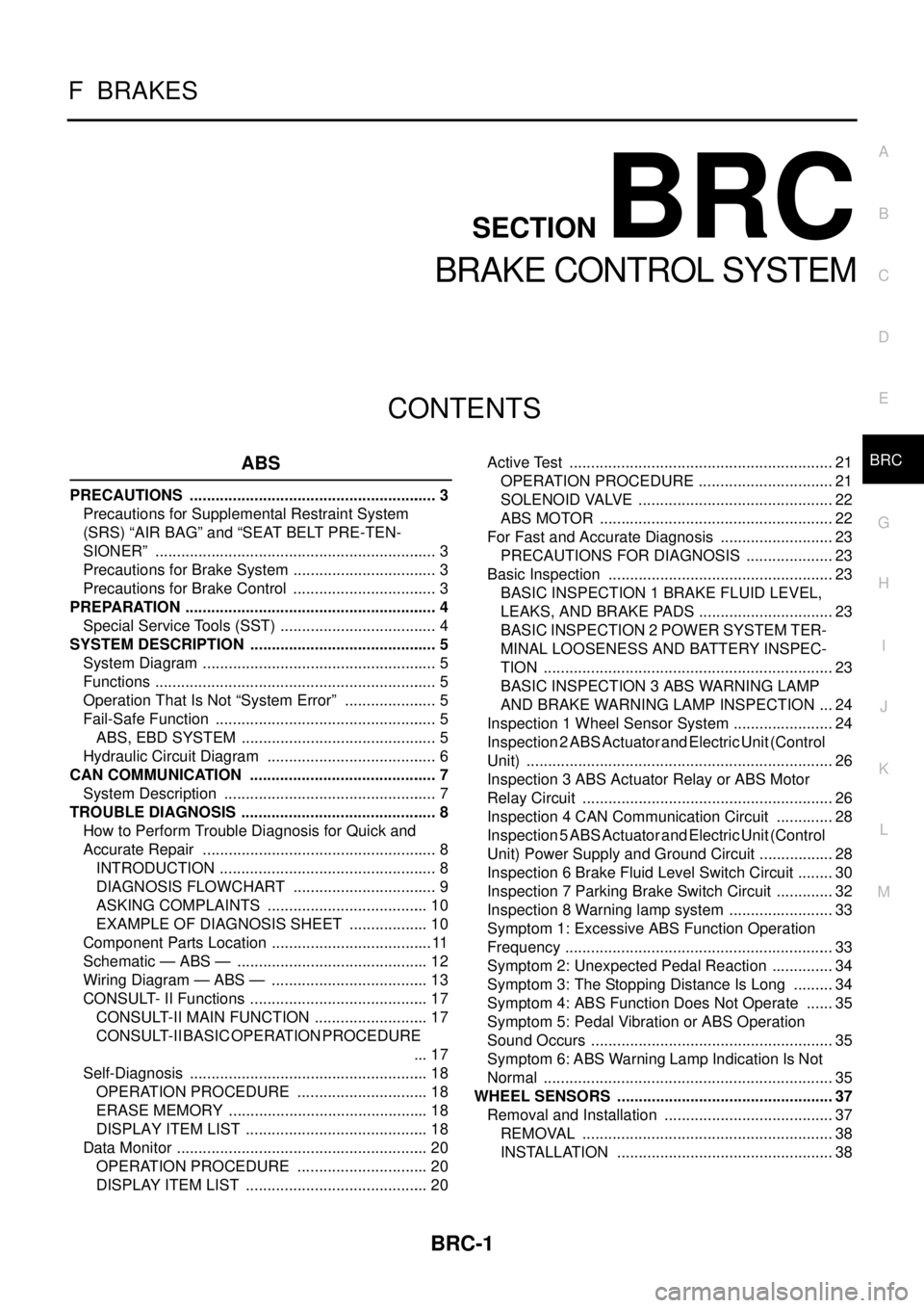
BRAKE CONTROL SYSTEM
F BRAKES
CONTENTS
C
D
E
G
H
I
J
K
L
M
SECTIONBRC
A
B
BRC
BRAKE CONTROL SYSTEM
ABS
PRECAUTIONS .......................................................... 3
Precautions for Supplemental Restraint System
(SRS)“AIRBAG”and“SEATBELTPRE-TEN-
SIONER” .................................................................. 3
Precautions for Brake System .................................. 3
Precautions for Brake Control .................................. 3
PREPARATION ........................................................... 4
Special Service Tools (SST) ..................................... 4
SYSTEM DESCRIPTION ............................................ 5
System Diagram ....................................................... 5
Functions .................................................................. 5
Operation That Is Not “System Error” ...................... 5
Fail-Safe Function .................................................... 5
ABS, EBD SYSTEM .............................................. 5
Hydraulic Circuit Diagram ........................................ 6
CAN COMMUNICATION ............................................ 7
System Description .................................................. 7
TROUBLE DIAGNOSIS .............................................. 8
How to Perform Trouble Diagnosis for Quick and
Accurate Repair ....................................................... 8
INTRODUCTION ................................................... 8
DIAGNOSIS FLOWCHART .................................. 9
ASKING COMPLAINTS ...................................... 10
EXAMPLE OF DIAGNOSIS SHEET ................... 10
Component Parts Location ...................................... 11
Schematic — ABS — ............................................. 12
Wiring Diagram — ABS — ..................................... 13
CONSULT- II Functions .......................................... 17
CONSULT-II MAIN FUNCTION ........................... 17
CONSULT-II BASIC OPERATION PROCEDURE
... 17
Self-Diagnosis ........................................................ 18
OPERATION PROCEDURE ............................... 18
ERASE MEMORY ............................................... 18
DISPLAY ITEM LIST ........................................... 18
Data Monitor ........................................................... 20
OPERATION PROCEDURE ............................... 20
DISPLAY ITEM LIST ........................................... 20Active Test .............................................................. 21
OPERATION PROCEDURE ................................ 21
SOLENOID VALVE .............................................. 22
ABS MOTOR ....................................................... 22
For Fast and Accurate Diagnosis ........................... 23
PRECAUTIONS FOR DIAGNOSIS ..................... 23
Basic Inspection ..................................................... 23
BASIC INSPECTION 1 BRAKE FLUID LEVEL,
LEAKS, AND BRAKE PADS ................................ 23
BASIC INSPECTION 2 POWER SYSTEM TER-
MINAL LOOSENESS AND BATTERY INSPEC-
TION .................................................................... 23
BASIC INSPECTION 3 ABS WARNING LAMP
AND BRAKE WARNING LAMP INSPECTION .... 24
Inspection 1 Wheel Sensor System ........................ 24
Inspection 2 ABS Actuator and Electric Unit (Control
Unit) ........................................................................ 26
Inspection 3 ABS Actuator Relay or ABS Motor
Relay Circuit ........................................................... 26
Inspection 4 CAN Communication Circuit .............. 28
Inspection 5 ABS Actuator and Electric Unit (Control
Unit) Power Supply and Ground Circuit .................. 28
Inspection 6 Brake Fluid Level Switch Circuit ......... 30
Inspection 7 Parking Brake Switch Circuit .............. 32
Inspection 8 Warning lamp system ......................... 33
Symptom 1: Excessive ABS Function Operation
Frequency ............................................................... 33
Symptom 2: Unexpected Pedal Reaction ............... 34
Symptom 3: The Stopping Distance Is Long .......... 34
Symptom 4: ABS Function Does Not Operate ....... 35
Symptom 5: Pedal Vibration or ABS Operation
Sound Occurs ......................................................... 35
Symptom 6: ABS Warning Lamp Indication Is Not
Normal .................................................................... 35
WHEEL SENSORS ................................................... 37
Removal and Installation ........................................ 37
REMOVAL ........................................................... 38
INSTALLATION ................................................... 38
Page 845 of 3171
![NISSAN NAVARA 2005 Repair Workshop Manual TROUBLE DIAGNOSIS
BRC-23
[ABS]
C
D
E
G
H
I
J
K
L
MA
B
BRC
For Fast and Accurate DiagnosisEFS005TX
PRECAUTIONS FOR DIAGNOSIS
lBefore performing diagnosis, always read precautions. Refer toBRC-17, "CONS NISSAN NAVARA 2005 Repair Workshop Manual TROUBLE DIAGNOSIS
BRC-23
[ABS]
C
D
E
G
H
I
J
K
L
MA
B
BRC
For Fast and Accurate DiagnosisEFS005TX
PRECAUTIONS FOR DIAGNOSIS
lBefore performing diagnosis, always read precautions. Refer toBRC-17, "CONS](/manual-img/5/57362/w960_57362-844.png)
TROUBLE DIAGNOSIS
BRC-23
[ABS]
C
D
E
G
H
I
J
K
L
MA
B
BRC
For Fast and Accurate DiagnosisEFS005TX
PRECAUTIONS FOR DIAGNOSIS
lBefore performing diagnosis, always read precautions. Refer toBRC-17, "CONSULT- II Functions".
lAfter diagnosis is finished, be sure to erase memory. Refer toBRC-18, "ERASE MEMORY".
lWhen checking continuity and voltage between units, be sure to check for disconnection, looseness,
bend, or collapse of connector terminals. If any malfunction is found, repair or replace connector termi-
nals.
lFor intermittent symptoms, possible cause is malfunction in harness, harness connector, or terminals.
Move harness, harness connector, and terminals to check for poor connections.
lIf a circuit tester is used for check, be careful not to forcibly extend any connector terminal.
lABS system electrically controls brake operation and engine output. Following symptoms may be caused
by normal operations:
Basic InspectionEFS005TY
BASIC INSPECTION 1 BRAKE FLUID LEVEL, LEAKS, AND BRAKE PADS
1. Check fluid level in the brake reservoir tank. If fluid level is low, refill brake fluid.
2. Check brake tube and around ABS actuator and electric unit (control unit) for leaks. If leakage or seepage
is found, check the following items.
lIf ABS actuator and electric unit (control unit) connection is loose, tighten brake tube to the specified
torque and re-conduct the leak inspection to make sure there are no leakage.
lIf there is damage to the connection flare nut or ABS actuator and electric unit (control unit) screw,
replace the damaged part and re-conduct the leak inspection to make sure there are no leakage.
lIf there is leakage or seepage at any location other than ABS actuator and electric unit (control unit)
connection, wipe away leakage or seepage with clean cloth. Then inspect again and confirm than there
is on leakage.
lIf there is leakage from ABS actuator and electric unit (control unit), wipe away leakage or seepage with
clean cloth. Then inspect again. If there is leakage or seepage, replace ABS actuator and electric unit
(control unit).
CAUTION:
ABS actuator and electric unit (control unit) body cannot be disassembled.
3. Check brake pad degree of wear. Refer toBR-24, "
PAD WEAR INSPECTION"in “Front Disc Brake” and
BR-32, "
Lining Thickness Inspection"in “Rear Drum Brake”.
BASIC INSPECTION 2 POWER SYSTEM TERMINAL LOOSENESS AND BATTERY INSPECTION
Make sure battery positive cable, negative cable and ground connection are not loose. In addition, check the
battery voltage to make sure it has not dropped and alternator is normal.
Symptom Symptom description Result
Motor operation noiseThis is noise of motor inside ABS actuator and electric unit (control unit). Slight
noise may occur during ABS operation.
Normal
Just after engine starts, motor operating noise may be heard. This is a normal
status of the system operation check.
System operation check noiseWhen engine starts, slight “click” noise may be heard from engine compart-
ment. This is normal and is part of system operation check.Normal
ABS operation
(Longer stopping distance)When driving on roads with a low coefficient of friction, such as snowy roads
or gravel roads, the stopping distance is sometimes longer for vehicles
equipped with ABS. Therefore, when driving on such roads, drive at a suffi-
ciently reduced speed to be safe.Normal
Page 1633 of 3171

HOW TO USE THIS MANUAL
GI-11
C
D
E
F
G
H
I
J
K
L
MB
GI
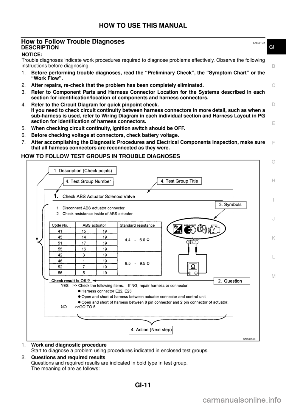
How to Follow Trouble DiagnosesEAS001GX
DESCRIPTION
NOTICE:
Trouble diagnoses indicate work procedures required to diagnose problems effectively. Observe the following
instructions before diagnosing.
1.Before performing trouble diagnoses, read the “Preliminary Check”, the “Symptom Chart” or the
“Work Flow”.
2.After repairs, re-check that the problem has been completely eliminated.
3.Refer to Component Parts and Harness Connector Location for the Systems described in each
section for identification/location of components and harness connectors.
4.Refer to the Circuit Diagram for quick pinpoint check.
If you need to check circuit continuity between harness connectors in more detail, such as when a
sub-harness is used, refer to Wiring Diagram in each individual section and Harness Layout in PG
section for identification of harness connectors.
5.When checking circuit continuity, ignition switch should be OFF.
6.Before checking voltage at connectors, check battery voltage.
7.After accomplishing the Diagnostic Procedures and Electrical Components Inspection, make sure
that all harness connectors are reconnected as they were.
HOW TO FOLLOW TEST GROUPS IN TROUBLE DIAGNOSES
1.Work and diagnostic procedure
Start to diagnose a problem using procedures indicated in enclosed test groups.
2.Questions and required results
Questions and required results are indicated in bold type in test group.
The meaning of are as follows:
SAIA0256E
Page 1639 of 3171

HOW TO USE THIS MANUAL
GI-17
C
D
E
F
G
H
I
J
K
L
MB
GI
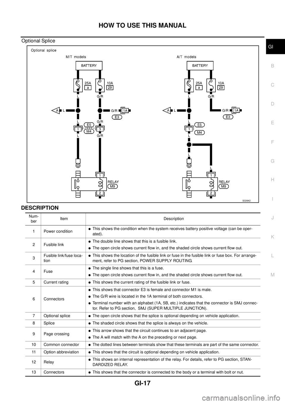
Optional Splice
DESCRIPTION
SGI942
Num-
berItem Description
1 Power condition
lThis shows the condition when the system receives battery positive voltage (can be oper-
ated).
2 Fusible link
lThe double line shows that this is a fusible link.
lThe open circle shows current flow in, and the shaded circle shows current flow out.
3Fusible link/fuse loca-
tion
lThis shows the location of the fusible link or fuse in the fusible link or fuse box. For arrange-
ment, refer to PG section, POWER SUPPLY ROUTING.
4Fuse
lThe single line shows that this is a fuse.
lThe open circle shows current flow in, and the shaded circle shows current flow out.
5 Current rating
lThis shows the current rating of the fusible link or fuse.
6 Connectors
lThis shows that connector E3 is female and connector M1 is male.
lThe G/R wire is located in the 1A terminal of both connectors.
lTerminal number with an alphabet (1A, 5B, etc.) indicates that the connector is SMJ connec-
tor. Refer to PG section, SMJ (SUPER MULTIPLE JUNCTION).
7 Optional splice
lThe open circle shows that the splice is optional depending on vehicle application.
8Splice
lThe shaded circle shows that the splice is always on the vehicle.
9 Page crossing
lThis arrow shows that the circuit continues to an adjacent page.
lThe A will match with the A on the preceding or next page.
10 Common connector
lThe dotted lines between terminals show that these terminals are part of the same connector.
11 Option abbreviation
lThis shows that the circuit is optional depending on vehicle application.
12 Relay
lThis shows an internal representation of the relay. For details, refer to PG section, STAN-
DARDIZED RELAY.
13 Connectors
lThis shows that the connector is connected to the body or a terminal with bolt or nut.
Page 1712 of 3171
![NISSAN NAVARA 2005 Repair Workshop Manual GW-26
POWER WINDOW SYSTEM
BCM Power Supply and Ground Circuit Check
EIS00B7T
1.CHECK FUSE
lCheck 10A fuse [No. 1, located in the fuse block (J/B)].
lCheck 10A fuse [No. 21, located in the fuse block ( NISSAN NAVARA 2005 Repair Workshop Manual GW-26
POWER WINDOW SYSTEM
BCM Power Supply and Ground Circuit Check
EIS00B7T
1.CHECK FUSE
lCheck 10A fuse [No. 1, located in the fuse block (J/B)].
lCheck 10A fuse [No. 21, located in the fuse block (](/manual-img/5/57362/w960_57362-1711.png)
GW-26
POWER WINDOW SYSTEM
BCM Power Supply and Ground Circuit Check
EIS00B7T
1.CHECK FUSE
lCheck 10A fuse [No. 1, located in the fuse block (J/B)].
lCheck 10A fuse [No. 21, located in the fuse block (J/B)].
lCheck 50A fusible link (letterGlocated in the fuse and fusible link box).
NOTE:
Refer toGW-15, "
Component Parts and Harness Connector Location".
OK or NG
OK >> GO TO 2.
NG >> If fuse is blown, be sure to eliminate cause of malfunction before installing new fuse.
2.CHECK POWER SUPPLY CIRCUIT
1. Turn ignition switch OFF.
2. Disconnect BCM connector.
3. Turn ignition switch ON.
4. Check voltage between BCM connector M42, 43, 44 terminal 3,
41, 57 and ground.
OK or NG
OK >> GO TO 3.
NG >> Repair or replace harness.
3.CHECK GROUND CIRCUIT
1. Turn ignition switch OFF.
2. Disconnect BCM.
3. Check continuity between BCM connector M44 terminal 55 and
ground.
OK or NG
OK >> Power supply and ground circuit is OK.
NG >> Repair or replace harness.3 - Ground : Battery voltage
41 - Ground : Battery voltage
57 - Ground : Battery voltage
MIIB0733E
55 - Ground : Continuity should exist.
MIIB0594E