2005 NISSAN NAVARA wheel bolt torque
[x] Cancel search: wheel bolt torquePage 799 of 3171
BRAKE TUBE AND HOSE
BR-13
C
D
E
G
H
I
J
K
L
MA
B
BR
CAUTION:
lAll brake tubes and hoses must be free from excessive bending, twisting and pulling.
lMake sure that there is no interference with other parts when turning steering both clockwise and
counterclockwise.
lBrake tube and hose is an important safety part. Always disassemble the parts and retighten their
fittings, if a brake fluid leak is detected. Replace applicable part with a new one, if damaged part is
detected.
lBe careful not to splash brake fluid on painted areas; it may cause paint damage. If brake fluid is
splashed on painted surfaces of body, immediately wipe off them and wash it away with water.
lDo not bend or twist brake hose sharply, or strongly pull it.
lCover the open end of brake tube and hoses when disconnecting to prevent entrance of dirt.
lRefill with new brake fluid “DOT 3” or “DOT 4”.
lNever reuse drained brake fluid.
Removal and Installation of Front Brake Tube and Brake HoseEFS005SM
REMOVAL
1. Drain brake fluid. Refer toBR-10, "Drain and Refill".
2. Using a flare nut wrench, disconnect brake tube from brake hose.
3. Remove union bolt and remove brake hose from caliper assembly.
4. Remove lock plate and remove brake hose from vehicle.
INSTALLATION
1. Assemble the union bolt and copper washers to the brake hose.
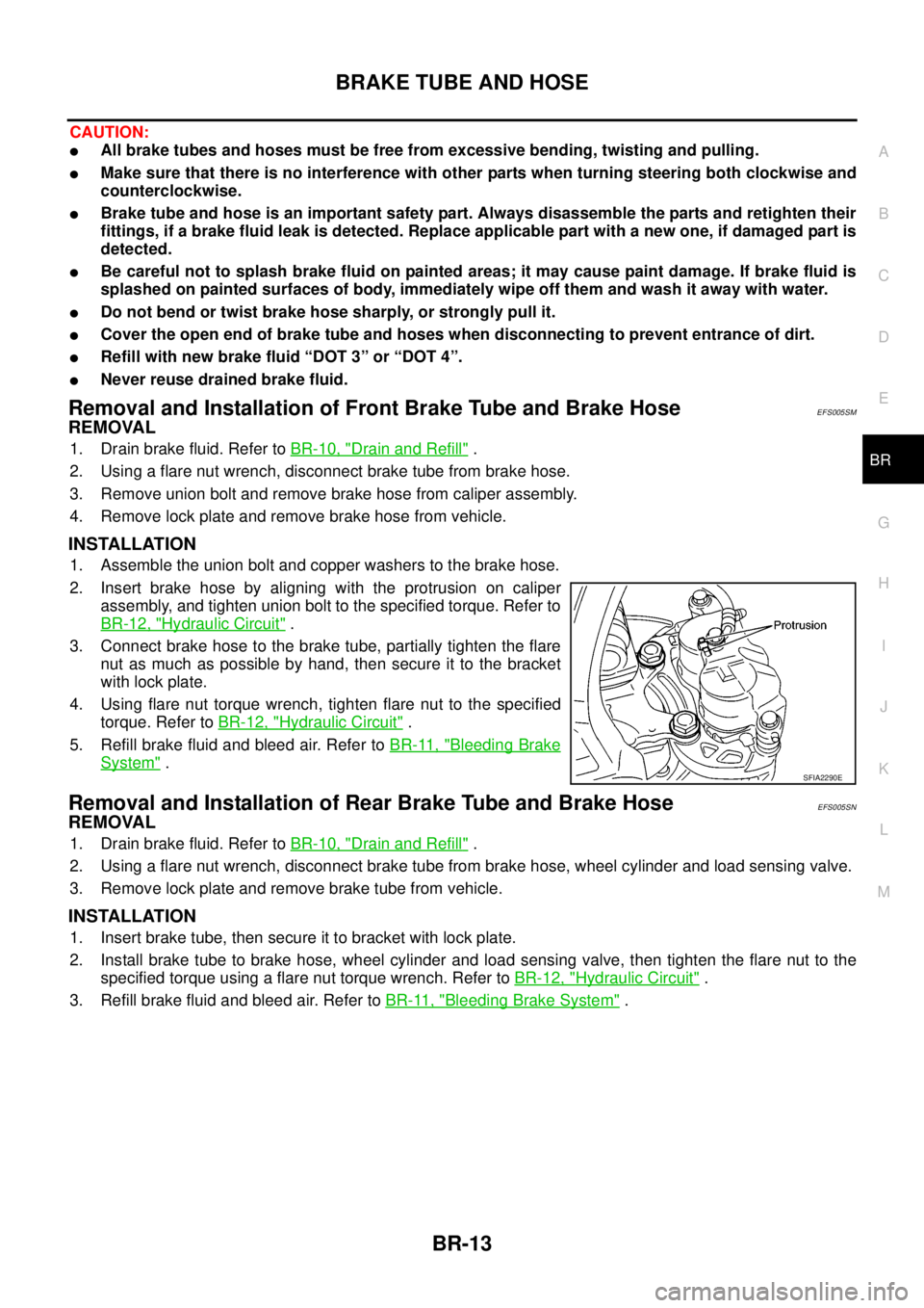
2. Insert brake hose by aligning with the protrusion on caliper
assembly, and tighten union bolt to the specified torque. Refer to
BR-12, "
Hydraulic Circuit".
3. Connect brake hose to the brake tube, partially tighten the flare
nut as much as possible by hand, then secure it to the bracket
with lock plate.
4. Using flare nut torque wrench, tighten flare nut to the specified
torque. Refer toBR-12, "
Hydraulic Circuit".
5. Refill brake fluid and bleed air. Refer toBR-11, "
Bleeding Brake
System".
Removal and Installation of Rear Brake Tube and Brake HoseEFS005SN
REMOVAL
1. Drain brake fluid. Refer toBR-10, "Drain and Refill".
2. Using a flare nut wrench, disconnect brake tube from brake hose, wheel cylinder and load sensing valve.
3. Remove lock plate and remove brake tube from vehicle.
INSTALLATION
1. Insert brake tube, then secure it to bracket with lock plate.
2. Install brake tube to brake hose, wheel cylinder and load sensing valve, then tighten the flare nut to the
specified torque using a flare nut torque wrench. Refer toBR-12, "
Hydraulic Circuit".
3. Refill brake fluid and bleed air. Refer toBR-11, "
Bleeding Brake System".
SFIA2290E
Page 812 of 3171
BR-26
FRONT DISC BRAKE
Removal and Installation of Brake Caliper Assembly
EFS005T1
REMOVAL
1. Remove tyre from vehicle.
2. Fasten disc rotor using wheel nut.
CAUTION:
Align the matching marks of disc rotor and wheel hub, which were marked at the time of removal
when reusing disc rotor.
3. Drain brake fluid. Refer toBR-10, "
Drain and Refill".
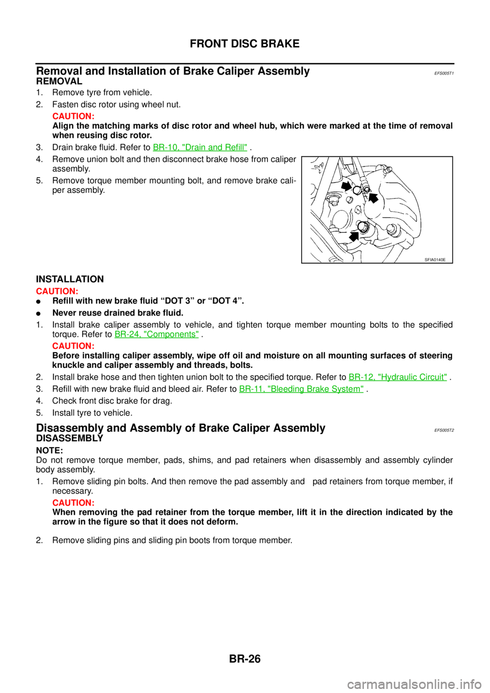
4. Remove union bolt and then disconnect brake hose from caliper
assembly.
5. Remove torque member mounting bolt, and remove brake cali-
per assembly.
INSTALLATION
CAUTION:
lRefill with new brake fluid “DOT 3” or “DOT 4”.
lNever reuse drained brake fluid.
1. Install brake caliper assembly to vehicle, and tighten torque member mounting bolts to the specified
torque. Refer toBR-24, "
Components".
CAUTION:
Before installing caliper assembly, wipe off oil and moisture on all mounting surfaces of steering
knuckle and caliper assembly and threads, bolts.
2. Install brake hose and then tighten union bolt to the specified torque. Refer toBR-12, "
Hydraulic Circuit".
3. Refill with new brake fluid and bleed air. Refer toBR-11, "
Bleeding Brake System".
4. Check front disc brake for drag.
5. Install tyre to vehicle.
Disassembly and Assembly of Brake Caliper AssemblyEFS005T2
DISASSEMBLY
NOTE:
Do not remove torque member, pads, shims, and pad retainers when disassembly and assembly cylinder
body assembly.
1. Remove sliding pin bolts. And then remove the pad assembly and pad retainers from torque member, if
necessary.
CAUTION:
When removing the pad retainer from the torque member, lift it in the direction indicated by the
arrow in the figure so that it does not deform.
2. Remove sliding pins and sliding pin boots from torque member.
SFIA0140E
Page 814 of 3171
BR-28
FRONT DISC BRAKE
ASSEMBLY
CAUTION:
When assembling, use only rubber lubricant specified below.
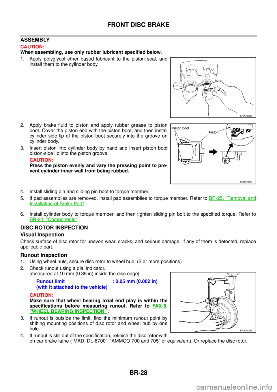
1. Apply polyglycol ether based lubricant to the piston seal, and
install them to the cylinder body.
2. Apply brake fluid to piston and apply rubber grease to piston
boot.Coverthepistonendwiththepistonboot,andtheninstall
cylinder side lip of the piston boot securely into the groove on
cylinder body.
3. Insert piston into cylinder body by hand and insert piston boot
piston-side lip into the piston groove.
CAUTION:
Press the piston evenly and vary the pressing point to pre-
vent cylinder inner wall from being rubbed.
4. Install sliding pin and sliding pin boot to torque member.
5. If pad assemblies are removed, install pad assemblies to torque member. Refer toBR-25, "
Removal and
Installation of Brake Pad".
6. Install cylinder body to torque member, and then tighten sliding pin bolt to the specified torque. Refer to
BR-24, "
Components".
DISC ROTOR INSPECTION
Visual Inspection
Check surface of disc rotor for uneven wear, cracks, and serious damage. If any of them is detected, replace
applicable part.
Runout Inspection
1. Using wheel nuts, secure disc rotor to wheel hub. (2 or more positions)
2. Check runout using a dial indicator.
[measured at 10 mm (0.39 in) inside the disc edge]
CAUTION:
Make sure that wheel bearing axial end play is within the
specifications before measuring runout. Refer toFAX-5,
"WHEEL BEARING INSPECTION".
3. If runout is outside the limit, find the minimum runout point by
shifting mounting positions of disc rotor and wheel hub by one
hole.
4. If runout is still out of the specification, refinish the disc rotor with
on-car brake lathe (“MAD, DL-8700”, “AMMCO 700 and 705” or equivalent). Or replace the disc rotor.
SFIA2920E
SFIA2279E
Runout limit
(with it attached to the vehicle):0.05mm(0.002in)
BRA0013D
Page 820 of 3171
BR-34
REAR DRUM BRAKE
Removal and Installation of Wheel Cylinder
EFS006AH
REMOVAL
1. Drain brake fluid. Refer toBR-10, "Drain and Refill".
2. Remove rear brake shoe assembly.
3. Remove brake tube from the wheel cylinder.
4. Remove bolts on the wheel cylinder, and then remove wheel cylinder from the back plate.
INSTALLATION
lInstallation is the reverse order of removal. Tighten bolts to the specified torque. Refer toBR-30, "Compo-
nents".
lRefill with new brake fluid and bleed air. Refer toBR-11, "Bleeding Brake System".
Disassembly and Assembly of Wheel CylinderEFS006AI
DISASSEMBLY
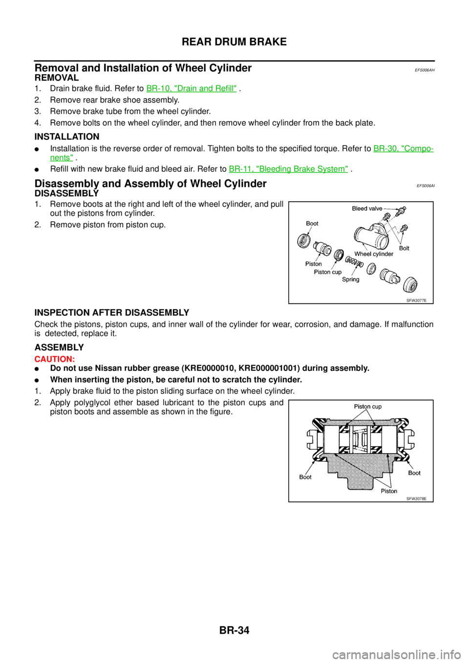
1. Remove boots at the right and left of the wheel cylinder, and pull
out the pistons from cylinder.
2. Remove piston from piston cup.
INSPECTION AFTER DISASSEMBLY
Check the pistons, piston cups, and inner wall of the cylinder for wear, corrosion, and damage. If malfunction
is detected, replace it.
ASSEMBLY
CAUTION:
lDo not use Nissan rubber grease (KRE0000010, KRE000001001) during assembly.
lWhen inserting the piston, be careful not to scratch the cylinder.
1. Apply brake fluid to the piston sliding surface on the wheel cylinder.
2. Apply polyglycol ether based lubricant to the piston cups and
piston boots and assemble as shown in the figure.
SFIA3077E
SFIA3078E
Page 860 of 3171
![NISSAN NAVARA 2005 Repair Workshop Manual BRC-38
[ABS]
WHEEL SENSORS
REMOVAL
Pay attention to the following when removing wheel sensor.
CAUTION:
lAs much as possible, avoid rotating wheel sensor when removing it. Pull wheel sensors out with-
NISSAN NAVARA 2005 Repair Workshop Manual BRC-38
[ABS]
WHEEL SENSORS
REMOVAL
Pay attention to the following when removing wheel sensor.
CAUTION:
lAs much as possible, avoid rotating wheel sensor when removing it. Pull wheel sensors out with-](/manual-img/5/57362/w960_57362-859.png)
BRC-38
[ABS]
WHEEL SENSORS
REMOVAL
Pay attention to the following when removing wheel sensor.
CAUTION:
lAs much as possible, avoid rotating wheel sensor when removing it. Pull wheel sensors out with-
out pulling on sensor harness.
lTake care to avoid damaging wheel sensor edges or rotor teeth. Remove wheel sensor first before
removing front or rear wheel hub. This is to avoid damage to wheel sensor wiring and loss of sen-
sor function.
INSTALLATION
Pay attention to the following when installing wheel sensor. Tighten installation bolts and nuts to the specified
torques.
lWhen installing, make sure there is no foreign material such as iron chips on and in the mounting hole of
the wheel sensor. Make sure no foreign material has been caught in the sensor rotor. Remove any foreign
material and clean the mount.
lWhen installing wheel sensor, be sure to press rubber grommets in until they lock at locations shown
above in figure. When installed, harness must not be twisted.
Page 1516 of 3171
EM-134
CYLINDER BLOCK
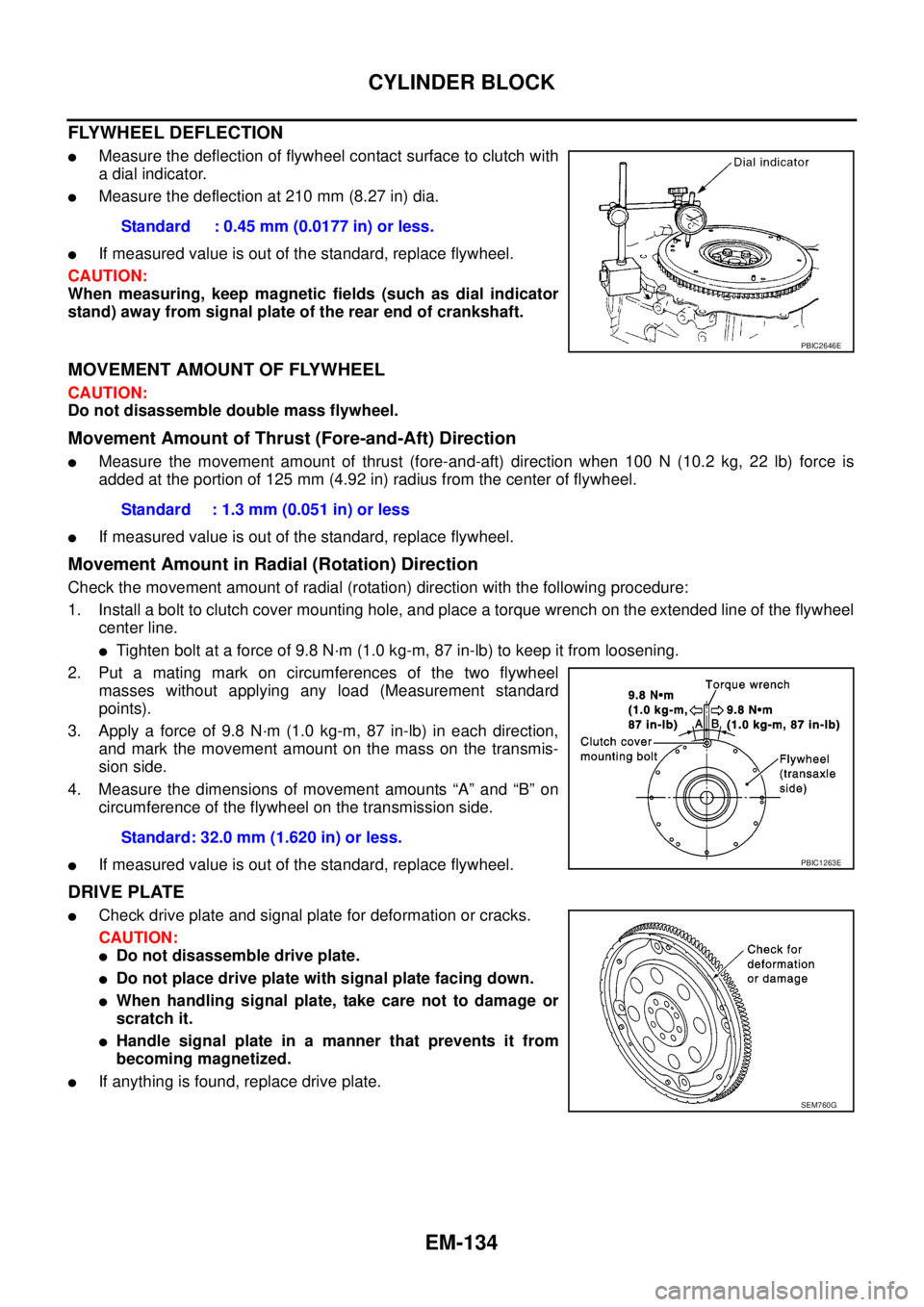
FLYWHEEL DEFLECTION
lMeasure the deflection of flywheel contact surface to clutch with
a dial indicator.
lMeasure the deflection at 210 mm (8.27 in) dia.
lIf measured value is out of the standard, replace flywheel.
CAUTION:
When measuring, keep magnetic fields (such as dial indicator
stand) away from signal plate of the rear end of crankshaft.
MOVEMENT AMOUNT OF FLYWHEEL
CAUTION:
Do not disassemble double mass flywheel.
Movement Amount of Thrust (Fore-and-Aft) Direction
lMeasure the movement amount of thrust (fore-and-aft) direction when 100 N (10.2 kg, 22 lb) force is
added at the portion of 125 mm (4.92 in) radius from the center of flywheel.
lIf measured value is out of the standard, replace flywheel.
Movement Amount in Radial (Rotation) Direction
Check the movement amount of radial (rotation) direction with the following procedure:
1. Install a bolt to clutch cover mounting hole, and place a torque wrench on the extended line of the flywheel
center line.
lTighten bolt at a force of 9.8 N·m (1.0 kg-m, 87 in-lb) to keep it from loosening.
2. Put a mating mark on circumferences of the two flywheel
masses without applying any load (Measurement standard
points).
3. Apply a force of 9.8 N·m (1.0 kg-m, 87 in-lb) in each direction,
and mark the movement amount on the mass on the transmis-
sion side.
4. Measure the dimensions of movement amounts “A” and “B” on
circumference of the flywheel on the transmission side.
lIf measured value is out of the standard, replace flywheel.
DRIVE PLATE
lCheck drive plate and signal plate for deformation or cracks.
CAUTION:
lDo not disassemble drive plate.
lDo not place drive plate with signal plate facing down.
lWhen handling signal plate, take care not to damage or
scratch it.
lHandle signal plate in a manner that prevents it from
becoming magnetized.
lIf anything is found, replace drive plate.Standard : 0.45 mm (0.0177 in) or less.
PBIC2646E
Standard : 1.3 mm (0.051 in) or less
Standard: 32.0 mm (1.620 in) or less.
PBIC1263E
SEM760G
Page 1537 of 3171
WHEEL HUB
FAX-5
C
E
F
G
H
I
J
K
L
MA
B
FA X
WHEEL HUBPFP:43202
On-Vehicle Inspection and ServiceEDS003I7
Make sure the mounting conditions (looseness, backlash) of each component and component status (wear,
damage) are normal.
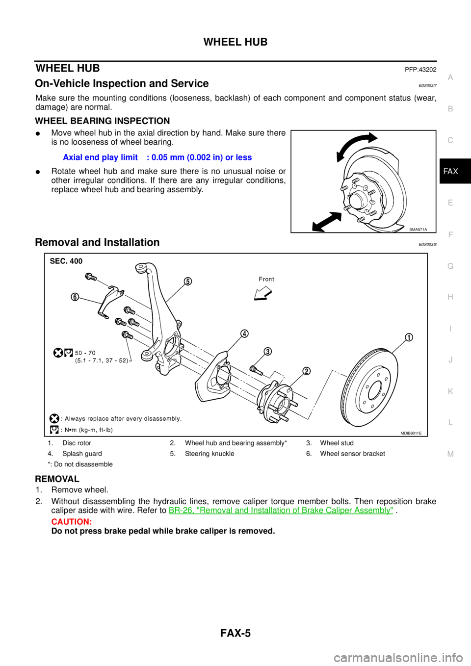
WHEEL BEARING INSPECTION
lMove wheel hub in the axial direction by hand. Make sure there
is no looseness of wheel bearing.
lRotate wheel hub and make sure there is no unusual noise or
other irregular conditions. If there are any irregular conditions,
replace wheel hub and bearing assembly.
Removal and InstallationEDS003I8
REMOVAL
1. Remove wheel.
2. Without disassembling the hydraulic lines, remove caliper torque member bolts. Then reposition brake
caliper aside with wire. Refer toBR-26, "
Removal and Installation of Brake Caliper Assembly".
CAUTION:
Do not press brake pedal while brake caliper is removed.Axial end play limit : 0.05 mm (0.002 in) or less
SMA571A
1. Disc rotor 2. Wheel hub and bearing assembly* 3. Wheel stud
4. Splash guard 5. Steering knuckle 6. Wheel sensor bracket
*: Do not disassemble
MDIB9011E
Page 1555 of 3171
FRONT OIL SEAL
FFD-9
C
E
F
G
H
I
J
K
L
MA
B
FFD
FRONT OIL SEALPFP:38189
Removal and InstallationEDS00353
CAUTION:
Verify identification stamp of replacement frequency put in the lower part of gear carrier to determine
replacement for collapsible spacer when replacing front oil seal. Refer toFFD-9, "
IDENTIFICATION
STAMP OF REPLACEMENT FREQUENCY OF FRONT OIL SEAL". If necessary collapsible spacer
replacement, remove final drive assembly and disassemble it to replace front oil seal and collapsible
spacer. Refer toFFD-15, "
Removal and Installation"andFFD-17, "Disassembly and Assembly".
NOTE:
The reuse of collapsible spacer is prohibited in principle. However, it is reusable on a one-time basis
only in cases when replacing front oil seal.
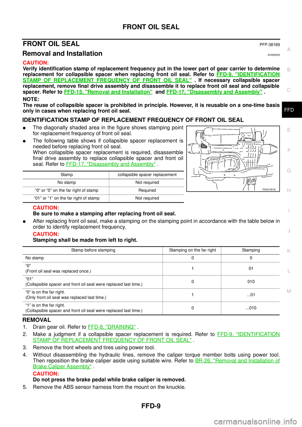
IDENTIFICATION STAMP OF REPLACEMENT FREQUENCY OF FRONT OIL SEAL
lThe diagonally shaded area in the figure shows stamping point
for replacement frequency of front oil seal.
lThe following table shows if collapsible spacer replacement is
needed before replacing front oil seal.
When collapsible spacer replacement is required, disassemble
final drive assembly to replace collapsible spacer and front oil
seal. Refer toFFD-17, "
Disassembly and Assembly".
CAUTION:
Be sure to make a stamping after replacing front oil seal.
lAfter replacing front oil seal, make a stamping on the stamping point in accordance with the table below in
order to identify replacement frequency.
CAUTION:
Stamping shall be made from left to right.
REMOVAL
1. Drain gear oil. Refer toFFD-8, "DRAINING".
2. Make a judgment if a collapsible spacer replacement is required. Refer toFFD-9, "
IDENTIFICATION
STAMP OF REPLACEMENT FREQUENCY OF FRONT OIL SEAL".
3. Remove the front wheels and tires using power tool.
4. Without disassembling the hydraulic lines, remove the caliper torque member bolts using power tool.
Then reposition the brake caliper aside using suitable wire. Refer toBR-26, "
Removal and Installation of
Brake Caliper Assembly".
CAUTION:
Do not press the brake pedal while brake caliper is removed.
5. Remove the ABS sensor harness from the mount on the knuckle.
Stamp collapsible spacer replacement
No stamp Not required
“0” or “0” on the far right of stamp Required
“01” or “1” on the far right of stamp Not required
PDIA1001E
Stamp before stamping Stamping on the far right Stamping
No stamp00
“0”
(Front oil seal was replaced once.)101
“01”
(Collapsible spacer and front oil seal were replaced last time.)0010
“0”isonthefarright.
(Only front oil seal was replaced last time.)1 ...01
“1”isonthefarright.
(Collapsible spacer and front oil seal were replaced last time.)0 ...010