2005 NISSAN NAVARA seat adjustment
[x] Cancel search: seat adjustmentPage 489 of 3171

AV-1
AUDIO-VISUAL SYSTEM
K ELECTRICAL
CONTENTS
C
D
E
F
G
H
I
J
L
M
SECTIONAV
A
B
AV
AUDIO-VISUAL SYSTEM
PRECAUTIONS .......................................................... 3
Precautions for Supplemental Restraint System
(SRS)“AIRBAG”and“SEATBELTPRE-TEN-
SIONER” .................................................................. 3
Wiring Diagrams and Trouble Diagnosis .................. 3
SYSTEM DESCRIPTION ............................................ 4
System Functions ..................................................... 4
AUDIO ................................................................... 4
NATS AUDIO LINK (WITHOUT NAVIGATION
SYSTEM) .............................................................. 4
VEHICLE INFORMATION SYSTEM ..................... 5
NAVIGATION SYSTEM ......................................... 5
HANDS-FREE PHONE ......................................... 7
Component Description ............................................ 8
AUDIO UNIT ......................................................... 8
NAVI CONTROL UNIT .......................................... 8
GPS ANTENNA .................................................... 9
DISPLAY UNIT ...................................................... 9
AV SWITCH .......................................................... 9
Component Parts Location ..................................... 10
Location Of Antenna .............................................. 10
Schematic — AUDIO — / With 1CD Player Type... 12
Wiring Diagram — AUDIO — / With 1CD Player Type
... 13
Schematic — AUDIO — / With 6CD Player Type... 16
Wiring Diagram — AUDIO — / With 6CD Player Type
... 17
Schematic — NAVI — ............................................ 20
Wiring Diagram — NAVI — .................................... 21
Schematic — NAVI — / COMM .............................. 28
Wiring Diagram — NAVI — / COMM ...................... 29
Wiring Diagram — TELEPHONE (PRE WIRE) —
/ Without NAVI ........................................................ 32
CAN Communication .............................................. 33
SYSTEM DESCRIPTION .................................... 33
TERMINALS AND REFERENCE VALUE FOR CON-
TROL UNIT ............................................................... 34
Audio Unit (1CD Player Type) ................................ 34
Audio Unit (6CD Player Type) Without NAVI .......... 35Audio Unit (With NAVI) ........................................... 37
NAVI Control Unit ................................................... 38
Display Unit ............................................................ 41
DIAGNOSIS SYSTEM ............................................... 44
Navigation System Diagnosis Function .................. 44
On Bord Self-Diagnosis Function ........................... 44
DESCRIPTION .................................................... 44
DIAGNOSIS ITEM ............................................... 44
OPERATION PROCEDURE ................................ 45
Self Diagnosis Mode ............................................... 46
ERROR DETECTION RANGE OF SELF-DIAG-
NOSIS MODE ..................................................... 47
DIAGNOSIS RESULTS ....................................... 47
Confirmation/Adjustment Mode .............................. 48
SCREEN TROUBLE DIAGNOSIS ...................... 49
VEHICLE SIGNALS ............................................ 49
SPEAKER TEST ................................................. 50
NAVIGATION ....................................................... 50
ERROR HISTORY ............................................... 51
VEHICLE CAN DIAGNOSIS ............................... 53
AV COMM DIAGNOSIS ....................................... 54
HANDSFREE PHONE ........................................ 54
BLUETOOTH ....................................................... 54
DELETE UNIT CONNECTION LOG ................... 55
CONSULT-II Functions ........................................... 56
CONSULT-II FUNCTIONS ................................... 56
CONSULT-II BASIC OPERATION PROCEDURE
... 56
SELF-DIAG RESULTS ........................................ 56
DATA MONITOR ................................................. 58
AV COMM MONITOR .......................................... 59
ECU PART NUMBER .......................................... 60
TROUBLE DIAGNOSIS ............................................ 61
Navigation System .................................................. 61
RGB Image ............................................................. 61
Voice Activated Control System ............................. 62
Steering Wheel Switch ............................................ 63
Component Parts Inspection .................................. 63
STEERING WHEEL SWITCH UNIT INSPEC-
Page 585 of 3171
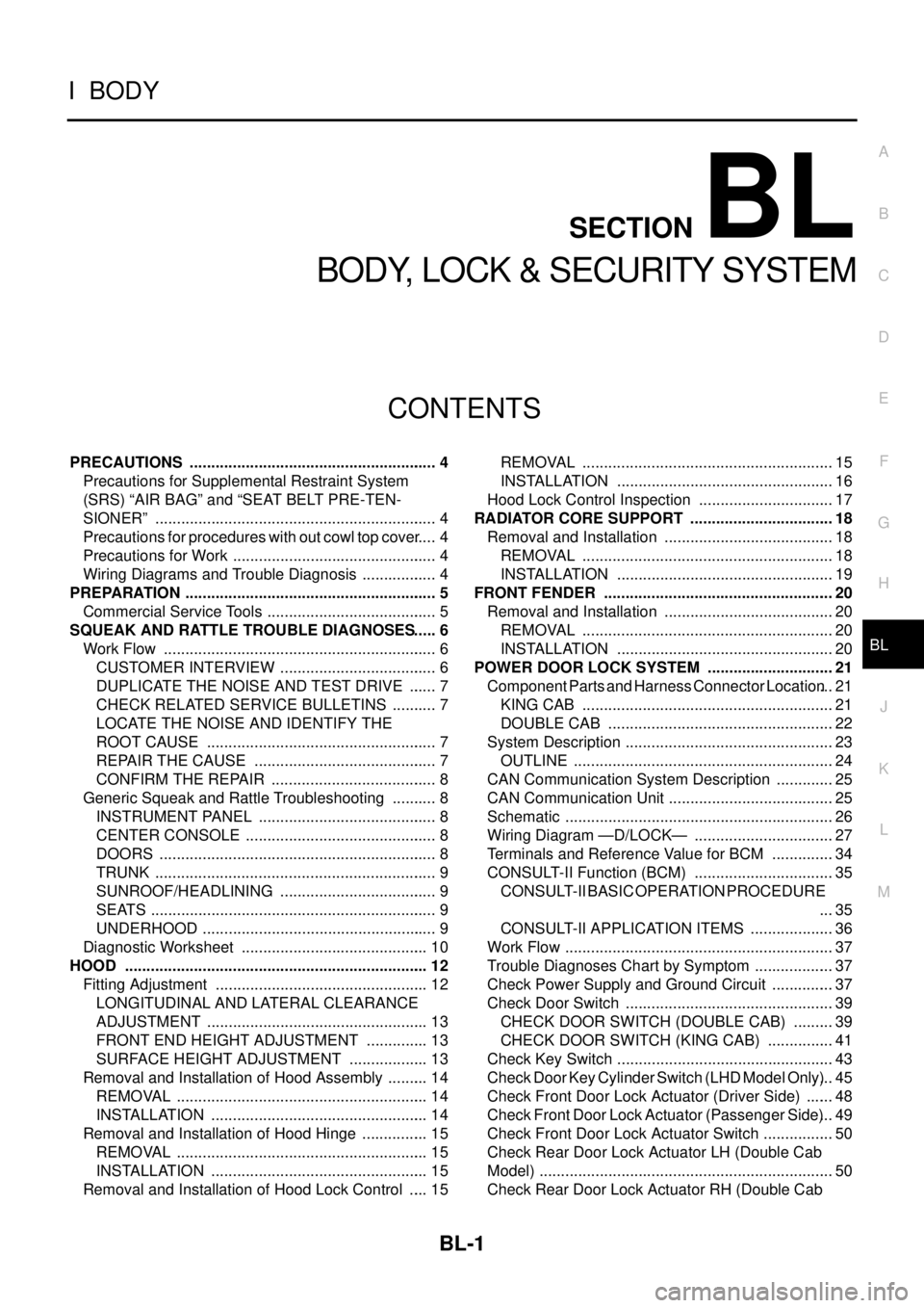
BL-1
BODY, LOCK & SECURITY SYSTEM
IBODY
CONTENTS
C
D
E
F
G
H
J
K
L
M
SECTIONBL
A
B
BL
BODY, LOCK & SECURITY SYSTEM
PRECAUTIONS .......................................................... 4
Precautions for Supplemental Restraint System
(SRS)“AIRBAG”and“SEATBELTPRE-TEN-
SIONER” .................................................................. 4
Precautions for procedures with out cowl top cover..... 4
Precautions for Work ................................................ 4
Wiring Diagrams and Trouble Diagnosis .................. 4
PREPARATION ........................................................... 5
Commercial Service Tools ........................................ 5
SQUEAK AND RATTLE TROUBLE DIAGNOSES..... 6
Work Flow ................................................................ 6
CUSTOMER INTERVIEW ..................................... 6
DUPLICATE THE NOISE AND TEST DRIVE ....... 7
CHECK RELATED SERVICE BULLETINS ........... 7
LOCATE THE NOISE AND IDENTIFY THE
ROOT CAUSE ...................................................... 7
REPAIR THE CAUSE ........................................... 7
CONFIRM THE REPAIR ....................................... 8
Generic Squeak and Rattle Troubleshooting ........... 8
INSTRUMENT PANEL .......................................... 8
CENTER CONSOLE ............................................. 8
DOORS ................................................................. 8
TRUNK .................................................................. 9
SUNROOF/HEADLINING ..................................... 9
SEATS ................................................................... 9
UNDERHOOD ....................................................... 9
Diagnostic Worksheet ............................................ 10
HOOD ....................................................................... 12
Fitting Adjustment .................................................. 12
LONGITUDINAL AND LATERAL CLEARANCE
ADJUSTMENT .................................................... 13
FRONT END HEIGHT ADJUSTMENT ............... 13
SURFACE HEIGHT ADJUSTMENT ................... 13
Removal and Installation of Hood Assembly .......... 14
REMOVAL ........................................................... 14
INSTALLATION ................................................... 14
Removal and Installation of Hood Hinge ................ 15
REMOVAL ........................................................... 15
INSTALLATION ................................................... 15
Removal and Installation of Hood Lock Control ..... 15REMOVAL ........................................................... 15
INSTALLATION ................................................... 16
Hood Lock Control Inspection ................................ 17
RADIATOR CORE SUPPORT .................................. 18
Removal and Installation ........................................ 18
REMOVAL ........................................................... 18
INSTALLATION ................................................... 19
FRONT FENDER ...................................................... 20
Removal and Installation ........................................ 20
REMOVAL ........................................................... 20
INSTALLATION ................................................... 20
POWER DOOR LOCK SYSTEM .............................. 21
Component Parts and Harness Connector Location... 21
KING CAB ........................................................... 21
DOUBLE CAB ..................................................... 22
System Description ................................................. 23
OUTLINE ............................................................. 24
CAN Communication System Description .............. 25
CAN Communication Unit ....................................... 25
Schematic ............................................................... 26
Wiring Diagram —D/LOCK— ................................. 27
Terminals and Reference Value for BCM ............... 34
CONSULT-II Function (BCM) ................................. 35
CONSULT-II BASIC OPERATION PROCEDURE
... 35
CONSULT-II APPLICATION ITEMS .................... 36
Work Flow ............................................................... 37
Trouble Diagnoses Chart by Symptom ................... 37
Check Power Supply and Ground Circuit ............... 37
Check Door Switch ................................................. 39
CHECK DOOR SWITCH (DOUBLE CAB) .......... 39
CHECK DOOR SWITCH (KING CAB) ................ 41
Check Key Switch ................................................... 43
Check Door Key Cylinder Switch (LHD Model Only)... 45
Check Front Door Lock Actuator (Driver Side) ....... 48
Check Front Door Lock Actuator (Passenger Side)... 49
Check Front Door Lock Actuator Switch ................. 50
Check Rear Door Lock Actuator LH (Double Cab
Model) ..................................................................... 50
Check Rear Door Lock Actuator RH (Double Cab
Page 588 of 3171
BL-4
PRECAUTIONS
PRECAUTIONS
PFP:00001
Precautions for Supplemental Restraint System (SRS) “AIR BAG” and “SEAT
BELT PRE-TENSIONER”
EIS00DHW
The Supplemental Restraint System such as “AIR BAG” and “SEAT BELT PRE-TENSIONER”, used along
with a front seat belt, helps to reduce the risk or severity of injury to the driver and front passenger for certain
types of collision. Information necessary to service the system safely is included in the SRS and SB section of
this Service Manual.
WARNING:
lTo avoid rendering the SRS inoperative, which could increase the risk of personal injury or death
in the event of a collision which would result in air bag inflation, all maintenance must be per-
formed by an authorized NISSAN/INFINITI dealer.
lImproper maintenance, including incorrect removal and installation of the SRS, can lead to per-
sonal injury caused by unintentional activation of the system. For removal of Spiral Cable and Air
Bag Module, see the SRS section.
lDo not use electrical test equipment on any circuit related to the SRS unless instructed to in this
Service Manual. SRS wiring harnesses can be identified by yellow and/or orange harnesses or
harness connectors.
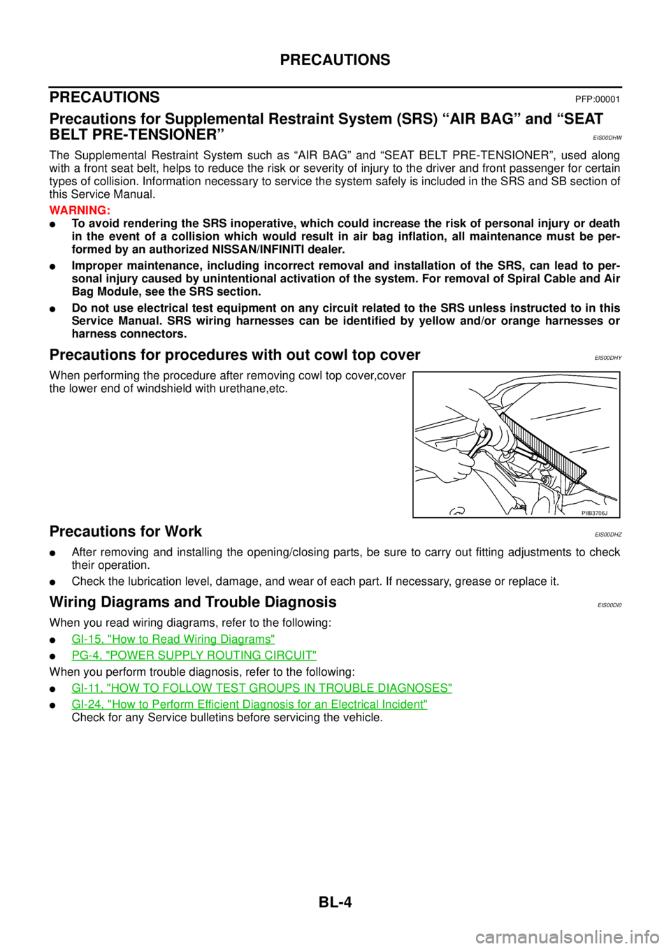
Precautions for procedures with out cowl top coverEIS00DHY
When performing the procedure after removing cowl top cover,cover
the lower end of windshield with urethane,etc.
Precautions for WorkEIS00DHZ
lAfter removing and installing the opening/closing parts, be sure to carry out fitting adjustments to check
their operation.
lCheck the lubrication level, damage, and wear of each part. If necessary, grease or replace it.
Wiring Diagrams and Trouble DiagnosisEIS00DI0
When you read wiring diagrams, refer to the following:
lGI-15, "How to Read Wiring Diagrams"
lPG-4, "POWER SUPPLY ROUTING CIRCUIT"
When you perform trouble diagnosis, refer to the following:
lGI-11, "HOW TO FOLLOW TEST GROUPS IN TROUBLE DIAGNOSES"
lGI-24, "How to Perform Efficient Diagnosis for an Electrical Incident"
Check for any Service bulletins before servicing the vehicle.
PIIB3706J
Page 593 of 3171

SQUEAK AND RATTLE TROUBLE DIAGNOSES
BL-9
C
D
E
F
G
H
J
K
L
MA
B
BL
TRUNK
Trunk noises are often caused by a loose jack or loose items put into the trunk by the owner.
In addition look for:
1. Trunk lid dumpers out of adjustment
2. Trunk lid striker out of adjustment
3. Trunk lid torsion bars knocking together
4. A loose license plate or bracket
Most of these incidents can be repaired by adjusting, securing or insulating the item(s) or component(s) caus-
ing the noise.
SUNROOF/HEADLINING
Noises in the sunroof/headlining area can often be traced to one of the following:
1. Sunroof lid, rail, linkage or seals making a rattle or light knocking noise
2. Sunvisor shaft shaking in the holder
3. Front or rear windshield touching headlining and squeaking
Again, pressing on the components to stop the noise while duplicating the conditions can isolate most of these
incidents. Repairs usually consist of insulating with felt cloth tape.
SEATS
When isolating seat noise it's important to note the position the seat is in and the load placed on the seat when
the noise is present. These conditions should be duplicated when verifying and isolating the cause of the
noise.
Cause of seat noise include:
1. Headrest rods and holder
2. A squeak between the seat pad cushion and frame
3. Rear seatback lock and bracket
These noises can be isolated by moving or pressing on the suspected components while duplicating the con-
ditions under which the noise occurs. Most of these incidents can be repaired by repositioning the component
or applying urethane tape to the contact area.
UNDERHOOD
Some interior noise may be caused by components under the hood or on the engine wall. The noise is then
transmitted into the passenger compartment.
Causes of transmitted underhood noise include:
1. Any component mounted to the engine wall
2. Components that pass through the engine wall
3. Engine wall mounts and connectors
4. Loose radiator mounting pins
5. Hood bumpers out of adjustment
6. Hood striker out of adjustment
These noises can be difficult to isolate since they cannot be reached from the interior of the vehicle. The best
method is to secure, move or insulate one component at a time and test drive the vehicle. Also, engine RPM
or load can be changed to isolate the noise. Repairs can usually be made by moving, adjusting, securing, or
insulating the component causing the noise.
Page 787 of 3171
BR-1
BRAKE SYSTEM
F BRAKES
CONTENTS
C
D
E
G
H
I
J
K
L
M
SECTIONBR
A
B
BR
BRAKE SYSTEM
PRECAUTIONS .......................................................... 3
Precautions for Supplemental Restraint System
(SRS)“AIRBAG”and“SEATBELTPRE-TEN-
SIONER” .................................................................. 3
Precautions for Brake System .................................. 3
PREPARATION ........................................................... 4
Special Service Tools ............................................... 4
Commercial Service Tools ........................................ 4
NOISE, VIBRATION AND HARSHNESS (NVH)
TROUBLESHOOTING ................................................ 5
NVH Troubleshooting Chart ..................................... 5
BRAKE PEDAL .......................................................... 6
Inspection and Adjustment ....................................... 6
ADJUSTMENT ...................................................... 7
Removal and Installation .......................................... 8
COMPONENTS .................................................... 8
REMOVAL ............................................................. 8
INSPECTION AFTER REMOVAL ......................... 9
INSTALLATION ..................................................... 9
BRAKE FLUID .......................................................... 10
On-board Inspection ............................................... 10
CHECKING BRAKE FLUID LEVEL .................... 10
Drain and Refill ....................................................... 10
Bleeding Brake System ........................................... 11
LHD MODEL ........................................................ 11
RHD MODEL ........................................................ 11
BRAKE TUBE AND HOSE ....................................... 12
Hydraulic Circuit ..................................................... 12
Removal and Installation of Front Brake Tube and
Brake Hose ............................................................ 13
REMOVAL ........................................................... 13
INSTALLATION ................................................... 13
Removal and Installation of Rear Brake Tube and
Brake Hose ............................................................ 13
REMOVAL ........................................................... 13
INSTALLATION ................................................... 13
Inspection after Installation .................................... 14
LOAD SENSING VALVE .......................................... 15
Removal and Installation ........................................ 15
REMOVAL ........................................................... 15INSTALLATION ................................................... 15
Inspection ............................................................... 16
INSPECTION ...................................................... 16
BRAKE MASTER CYLINDER .................................. 17
On-Board Inspection ............................................... 17
LEAK INSPECTION ............................................ 17
Removal and Installation ........................................ 17
REMOVAL ........................................................... 17
INSTALLATION ................................................... 17
Components ........................................................... 17
Disassembly and Assembly .................................... 18
DISASSEMBLY ................................................... 18
ASSEMBLY ......................................................... 18
BRAKE BOOSTER ................................................... 19
On-Vehicle Service ................................................. 19
OPERATING CHECK .......................................... 19
AIRTIGHT CHECK .............................................. 19
Removal and Installation ........................................ 20
COMPONENTS ................................................... 20
REMOVAL ........................................................... 20
INSPECTION AFTER REMOVAL ....................... 20
INSTALLATION ................................................... 21
VACUUM LINES ....................................................... 22
Component ............................................................. 22
Removal and Installation ........................................ 23
Inspection ............................................................... 23
VISUAL INSPECTION ......................................... 23
CHECK VALVE INSPECTION ............................. 23
FRONT DISC BRAKE ............................................... 24
On-Board Inspection ............................................... 24
PAD WEAR INSPECTION ................................... 24
Components ........................................................... 24
Removal and Installation of Brake Pad .................. 25
REMOVAL ........................................................... 25
INSTALLATION ................................................... 25
Removal and Installation of Brake Caliper Assembly
... 26
REMOVAL ........................................................... 26
INSTALLATION ................................................... 26
Disassembly and Assembly of Brake Caliper
Page 981 of 3171
EC-1
ENGINE CONTROL SYSTEM
B ENGINE
CONTENTS
C
D
E
F
G
H
I
J
K
L
M
SECTIONEC
A
EC
ENGINE CONTROL SYSTEM
INDEX FOR DTC ........................................................ 6
DTC No. Index ......................................................... 6
Alphabetical Index .................................................... 8
PRECAUTIONS ........................................................ 10
Precautions for Supplemental Restraint System
(SRS)“AIRBAG”and“SEATBELTPRE-TEN-
SIONER” ................................................................ 10
On Board Diagnostic (OBD) System of Engine ...... 10
Precautions ............................................................ 10
Wiring Diagrams and Trouble Diagnosis ................ 13
PREPARATION ......................................................... 14
Special Service Tools ............................................. 14
Commercial Service Tools ...................................... 14
ENGINE CONTROL SYSTEM .................................. 15
System Diagram ..................................................... 15
Vacuum Hose Drawing ........................................... 16
System Chart ......................................................... 18
Fuel Injection Control System ................................ 18
Fuel Injection Timing Control System ..................... 20
Air Conditioning Cut Control ................................... 20
Fuel Cut Control (At No Load & High Engine Speed)... 20
Crankcase Ventilation System ............................... 21
CAN Communication .............................................. 22
BASIC SERVICE PROCEDURE .............................. 23
Fuel Filter ............................................................... 23
Fuel Pump Learning Value Clearing ...................... 24
Injector Adjustment Value Registration .................. 25
ON BOARD DIAGNOSTIC (OBD) SYSTEM ............ 27
DTC Detection Logic .............................................. 27
Diagnostic Trouble Code (DTC) ............................. 27
Freeze Frame Data ................................................ 28
NATS (Nissan Anti-theft System) ........................... 28
Malfunction Indicator (MI) ....................................... 28
Relationship Between MI, DTC, CONSULT-II and
Driving Patterns ...................................................... 31
TROUBLE DIAGNOSIS ............................................ 33
Trouble Diagnosis Introduction ............................... 33
DTC Inspection Priority Chart ................................ 37
Basic Inspection ..................................................... 38
Symptom Matrix Chart ........................................... 42Engine Control Component Parts Location ............ 46
Circuit Diagram ....................................................... 50
ECM Harness Connector Terminal Layout ............. 52
ECM Terminals And Reference Value .................... 52
CONSULT-II Function (ENGINE) ............................ 59
CONSULT-II Reference Value in Data Monitor Mode
... 66
Major Sensor Reference Graph in Data Monitor
Mode ....................................................................... 69
TROUBLE DIAGNOSIS FOR INTERMITTENT INCI-
DENT ......................................................................... 70
Description .............................................................. 70
Diagnostic Procedure ............................................. 70
POWER SUPPLY AND GROUND CIRCUIT ............. 71
ECM Terminals and Reference Value ..................... 71
Wiring Diagram ....................................................... 72
Diagnostic Procedure ............................................. 73
Ground Inspection .................................................. 78
DTC U1000 CAN COMMUNICATION LINE .............. 79
Description .............................................................. 79
On Board Diagnosis Logic ...................................... 79
DTC Confirmation Procedure ................................. 79
Wiring Diagram ....................................................... 80
Diagnostic Procedure ............................................. 81
DTC P0016 CKP - CMP CORRELATION ................. 82
On Board Diagnosis Logic ...................................... 82
DTC Confirmation Procedure ................................. 82
Diagnostic Procedure ............................................. 82
DTC P0088 FUEL SYSTEM ...................................... 84
On Board Diagnosis Logic ...................................... 84
DTC Confirmation Procedure ................................. 84
Diagnostic Procedure ............................................. 84
Removal and Installation ........................................ 85
DTC P0089 FUEL PUMP .......................................... 86
On Board Diagnosis Logic ...................................... 86
DTC Confirmation Procedure ................................. 86
Diagnostic Procedure ............................................. 87
Removal and Installation ........................................ 87
DTC P0093 FUEL SYSTEM ...................................... 88
On Board Diagnosis Logic ...................................... 88
Page 1347 of 3171
SQUEAK AND RATTLE TROUBLE DIAGNOSES
EI-9
C
D
E
F
G
H
J
K
L
MA
B
EI
SEATS
When isolating seat noise it's important to note the position the seat is in and the load placed on the seat when
the noise is present. These conditions should be duplicated when verifying and isolating the cause of the
noise.
Cause of seat noise include:
1. Headrest rods and holder
2. A squeak between the seat pad cushion and frame
3. The rear seatback lock and bracket
These noises can be isolated by moving or pressing on the suspected components while duplicating the con-
ditions under which the noise occurs. Most of these incidents can be repaired by repositioning the component
or applying urethane tape to the contact area.
UNDERHOOD
Some interior noise may be caused by components under the hood or on the engine wall. The noise is then
transmitted into the passenger compartment.
Causes of transmitted underhood noise include:
1. Any component mounted to the engine wall
2. Components that pass through the engine wall
3. Engine wall mounts and connectors
4. Loose radiator mounting pins
5. Hood bumpers out of adjustment
6. Hood striker out of adjustment
These noises can be difficult to isolate since they cannot be reached from the interior of the vehicle. The best
method is to secure, move or insulate one component at a time and test drive the vehicle. Also, engine RPM
or load can be changed to isolate the noise. Repairs can usually be made by moving, adjusting, securing, or
insulating the component causing the noise.
Page 1578 of 3171
FFD-32
FRONT FINAL DRIVE ASSEMBLY
11. Apply anti-corrosive oil to the thread and seat of drive pinion
lock nut, and temporarily tighten drive pinion lock nut to drive
pinion.
CAUTION:
Do not reuse drive pinion lock nut.
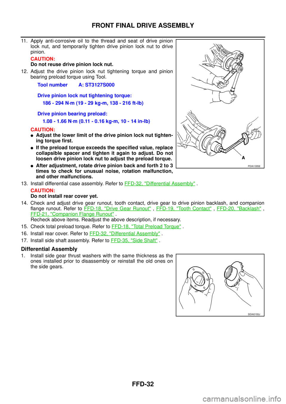
12. Adjust the drive pinion lock nut tightening torque and pinion
bearing preload torque using Tool.
CAUTION:
lAdjust the lower limit of the drive pinion lock nut tighten-
ing torque first.
lIf the preload torque exceeds the specified value, replace
collapsible spacer and tighten it again to adjust. Do not
loosen drive pinion lock nut to adjust the preload torque.
lAfter adjustment, rotate drive pinion back and forth 2 to 3
times to check for unusual noise, rotation malfunction,
and other malfunctions.
13. Install differential case assembly. Refer toFFD-32, "
Differential Assembly".
CAUTION:
Do not install rear cover yet.
14. Check and adjust drive gear runout, tooth contact, drive gear to drive pinion backlash, and companion
flange runout. Refer toFFD-18, "
Drive Gear Runout",FFD-19, "To o t h C o n t a c t",FFD-20, "Backlash",
FFD-21, "
Companion Flange Runout".
Recheck above items. Readjust the above description, if necessary.
15. Check total preload torque. Refer toFFD-18, "
Total Preload Torque".
16. Install rear cover. Refer toFFD-32, "
Differential Assembly".
17. Install side shaft assembly. Refer toFFD-35, "
Side Shaft".
Differential Assembly
1. Install side gear thrust washers with the same thickness as the
ones installed prior to disassembly or reinstall the old ones on
the side gears.Tool number A: ST3127S000
Drive pinion lock nut tightening torque:
186 - 294 N·m (19 - 29 kg-m, 138 - 216 ft-lb)
Drive pinion bearing preload:
1.08 - 1.66 N·m (0.11 - 0.16 kg-m, 10 - 14 in-lb)
PDIA1005E
SDIA0193J