2005 NISSAN NAVARA fuel
[x] Cancel search: fuelPage 1 of 3171
MODELD40 SERIES
2005 NISSAN EUROPE S.A.S.
All rights reserved. No part of this Electronic Service Manual may be reproduced or stored in a retrieval system, or transmitted in any
form, or by any means, electronic, mechanical, photocopying, recording or otherwise, without the prior written permission of Nissan
Europe S.A.S., Paris, France.
A GENERAL INFORMATION
B ENGINE
C TRANSMISSION/TRANSAXLE
D DRIVELINE/AXLE
E SUSPENSION F BRAKES
G STEERING H RESTRAINTS
I BODY
J AIR CONDITIONER
K ELECTRICAL
L MAINTENANCE
M INDEXGI General Information
EM Engine Mechanical
LU Engine Lubrication System
CO Engine Cooling System
EC Engine Control System
FL Fuel System
EX Exhaust System
ACC Accelerator Control System
CL Clutch
MTManualTransmission
AT Automatic Transmission
TF Transfer
PR Propeller Shaft
FFD Front Final Drive
RFD Rear Final Drive
FAX Front Axle
RAX Rear Axle
FSU Front Suspension
RSU Rear Suspension
WT Road Wheels & Tires
BR Brake System
PB Parking Brake System
BRC Brake Control System
PS Power Steering System
SB Seat Belts
SRS Supplemental Restraint System (SRS)
BL Body, Lock & Security System
GW Glasses, Window System & Mirrors
RF Roof
EI Exterior & Interior
IP Instrument Panel
SE Seat
ATC Automatic Air Conditioner
MTC Manual Air Conditioner
SC Starting & Charging System
LT Lighting System
DI Driver Information System
WW Wiper, Washer & Horn
BCS Body Control System
LAN LAN System
AV Audio, Visual & Telephone System
ACS Auto Cruise Control System
PG Power Supply, Ground & Circuit Elements
MA Maintenance
IDX Alphabetical Index
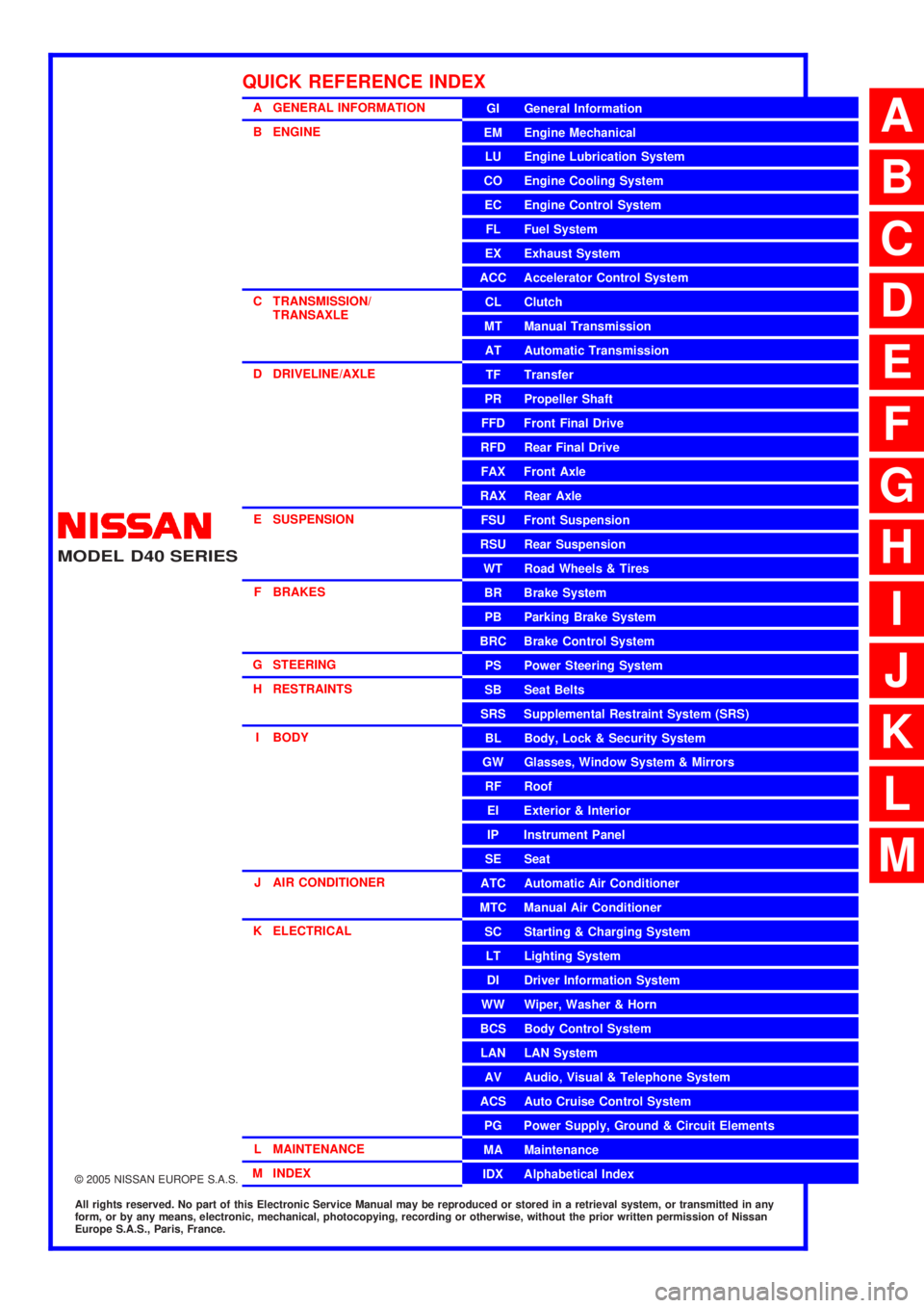
QUICK REFERENCE INDEX
A
B
C
D
E
F
G
H
I
J
K
L
M
Page 257 of 3171

TRANSMISSION ASSEMBLY
AT-249
D
E
F
G
H
I
J
K
L
MA
B
AT
5. Remove front valance center, engine undercover front, engine under cover middle and engine under
coverrear.RefertoEI-15, "
FRONT BUMPER".
6. Remove front cross member.
7. Remove main muffler. Refer toEX-2, "
EXHAUST SYSTEM".
8. Remove rear propeller shaft. Refer toPR-8, "
Removal and Installation".
9. Remove front propeller shaft. Refer toPR-4, "
Removal and Installation".
10. Remove starter motor. Refer toSC-31, "
Removal and Installation".
11. Remove control cable and bracket. Refer toAT- 2 1 0 , "
Control Cable Removal and Installation".
12. Disconnect fluid cooler tube.
13. Remove A/T fluid charging pipe from A/T assembly.
14. Remove O-ring from A/T fluid charging pipe.
15. Plug up openings such as A/T fluid charging pipe hole, etc.
16. Remove rear plate cover from rear plate.
17. Turn crankshaft to access and remove the four bolts for drive
plate and torque converter.
CAUTION:
When turning crankshaft, turn it clockwise as viewed from
the front of engine.
18. Support A/T assembly using a transmission jack.
CAUTION:
When setting transmission jack, be careful not to allow it to
collide against drain plug.
19. Remove protector (fuel tube), and then disconnect fuel tubes.
Refer toFL-7, "
FUEL COOLER". (4WD models)
20. Remove A/T cross member.
21. Remove engine mounting insulator (rear) from A/T assembly.
22. Disconnect the following:
lA/T assembly harness connector
lATP switch connector
l4LO switch connector
lWait detection switch connector
lTransfer control device connector
23. Support transfer assembly using a transmission jack. (4WD models)
24. Remove the wiring harness from bracket.
25. Remove bolts fixing A/T assembly to engine assembly.
26. Remove A/T assembly from the vehicle.
CAUTION:
lSecure torque converter to prevent it from dropping.
lSecure A/T assembly to a transmission jack.
27. Remove A/T air breather hose. Refer toAT- 2 4 3 , "
AIR
BREATHER HOSE".
28. Remove transfer assembly from A/T assembly. Refer toT F - 111 ,
"Removal and Installation". (4WD models)
SCIA6828E
SCIA6927E
SCIA2203E
Page 493 of 3171

SYSTEM DESCRIPTION
AV-5
C
D
E
F
G
H
I
J
L
MA
B
AV
Personal Audio Setting
The radio is designed to store several settings (volume, bass, treble, preset stations) with every NATS ignition
key used. Up to a maximum of 4 NATS keys can be registered. During the communication mentioned under
“Anti-Theft System”, the radio will recognize the used ignition key and select the accompanying settings.
VEHICLE INFORMATION SYSTEM
lThe status of audio system, fuel consumption, rear view monitor and navigation system are displayed.
lNAVI control unit receives the data signal from ECM, combination meter via CAN communication. It calcu-
lates the values of fuel economy, and trip computer from the received information and displays them.
NAVIGATION SYSTEM
Refer to Owner's Manual or navigation system Owner's Manual for navigation system operating instructions.
Location Detection Principle
The navigation system periodically calculates the vehicle's current
position according to the following three signals:
lTravel distance of the vehicle as determined by the vehicle
speed sensor
lTurning angle of the vehicle as determined by the gyroscope
(angular velocity sensor)
lDirection of vehicle travel as determined by the GPS antenna
(GPS information)
The current position of the vehicle is then identified by comparing the
calculated vehicle position with map data read from the map DVD-
ROM, which is stored in the DVD-ROM drive (map-matching), and
indicated on the screen as a vehicle mark. More accurate data is judged and used by comparing vehicle posi-
tion detection results found by the GPS with the result by map-matching.
The current vehicle position will be calculated by detecting the dis-
tance the vehicle moved from the previous calculation point and its
direction.
lTravel distance
Travel distance calculations are based on the vehicle speed
sensor input signal. Therefore, the calculation may become
incorrect as the tires wear down. To prevent this, an automatic
distance correction function has been adopted.
lTravel direction
Change in the travel direction of the vehicle is calculated by a
gyroscope (angular velocity sensor) and a GPS antenna (GPS
information). They have both advantages and disadvantages.
More accurate traveling direction is detected because priorities are set for the signals from these two
devices according to the situation.
No communication from IMMU to radio 1. If NATS is malfunctioning, check NATS
system.
2. After NATS is repaired, reset radio to
NEW state by authorized representative
of Clarion.After switching on the radio, the radio will
display “SECURE” after 1 minute. Further
use of radio is impossible until communica-
tion is established again, or after radio is
reset by authorized representative of Clar-
ion.
When initialized between ECM and IMMU. Radio needs to be reset to NEW status by
authorized representative of Clarion.After switching on the radio, it will display
“SECURE” after 1 minute. Item Service procedure Description
SKIB1058E
Type Advantage Disadvantage
Gyroscope
(angular velocity sensor)Can detect the vehicle's turning angle
quite accurately.Direction errors may accumulate when vehicle is
driven for long distances without stopping.
GPS antenna
(GPS information)Can detect the vehicle's travel direction
(North/South/East/West).Correct direction cannot be detected when vehi-
cle speed is low.
SEL684V
Page 549 of 3171
TROUBLE DIAGNOSIS
AV-61
C
D
E
F
G
H
I
J
L
MA
B
AV
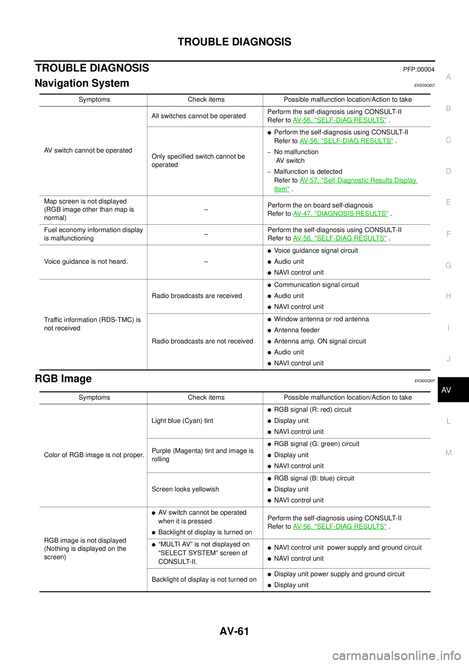
TROUBLE DIAGNOSISPFP:00004
Navigation SystemEKS00Q6O
RGB ImageEKS00Q6P
Symptoms Check items Possible malfunction location/Action to take
AV switch cannot be operatedAll switches cannot be operatedPerform the self-diagnosis using CONSULT-II
Refer toAV-56, "
SELF-DIAG RESULTS".
Only specified switch cannot be
operated
lPerform the self-diagnosis using CONSULT-II
Refer toAV-56, "
SELF-DIAG RESULTS".
–No malfunction
AV switch
–Malfunction is detected
Refer toAV-57, "
Self-Diagnostic Results Display
Item".
Map screen is not displayed
(RGB image other than map is
normal)–Perform the on board self-diagnosis
Refer toAV-47, "
DIAGNOSIS RESULTS".
Fuel economy information display
is malfunctioning–Perform the self-diagnosis using CONSULT-II
Refer toAV-56, "
SELF-DIAG RESULTS".
Voice guidance is not heard. –
lVoice guidance signal circuit
lAudio unit
lNAVI control unit
Traffic information (RDS-TMC) is
not receivedRadio broadcasts are received
lCommunication signal circuit
lAudio unit
lNAVI control unit
Radio broadcasts are not received
lWindow antenna or rod antenna
lAntenna feeder
lAntenna amp. ON signal circuit
lAudio unit
lNAVI control unit
Symptoms Check items Possible malfunction location/Action to take
Color of RGB image is not proper.Light blue (Cyan) tint
lRGB signal (R: red) circuit
lDisplay unit
lNAVI control unit
Purple (Magenta) tint and image is
rolling
lRGB signal (G: green) circuit
lDisplay unit
lNAVI control unit
Screen looks yellowish
lRGB signal (B: blue) circuit
lDisplay unit
lNAVI control unit
RGB image is not displayed
(Nothing is displayed on the
screen)
lAV switch cannot be operated
when it is pressed
lBacklight of display is turned onPerform the self-diagnosis using CONSULT-II
Refer toAV-56, "SELF-DIAG RESULTS".
l“MULTI AV” is not displayed on
“SELECT SYSTEM” screen of
CONSULT-II.lNAVI control unit power supply and ground circuit
lNAVI control unit
Backlight of display is not turned on
lDisplay unit power supply and ground circuit
lDisplay unit
Page 586 of 3171

BL-2
Model) ..................................................................... 51
Check RH and LH Rear Door Lock Actuator Switch... 51
Check Door Lock/Unlock Switch ............................ 52
Check Door Lock/Unlock Switch Indicator .............. 53
POWER DOOR LOCK — SUPER LOCK — ............ 55
Component Parts and Harness Connector Location... 55
KING CAB ........................................................... 55
DOUBLE CAB ..................................................... 56
System Description ................................................. 57
OUTLINE ............................................................. 58
OPERATION ........................................................ 58
CAN Communication System Description .............. 59
CAN Communication Unit ....................................... 59
Schematic ............................................................... 60
Wiring Diagram —D/LOCK— ................................. 61
Terminals and Reference Value for BCM ................ 69
CONSULT-II Function (BCM) .................................. 70
CONSULT-II BASIC OPERATION PROCEDURE
... 70
CONSULT-II APPLICATION ITEMS .................... 71
Work Flow ............................................................... 72
Trouble Diagnoses Chart by Symptom ................... 72
Check Power Supply and Ground Circuit ............... 73
Check Door Switch ................................................. 74
CHECK DOOR SWITCH (DOUBLE CAB) .......... 74
CHECK DOOR SWITCH (KING CAB) ................ 76
Check Key Switch ................................................... 78
Check Front Door Lock Actuator (Driver Side) ....... 80
Check Front Door Lock Actuator (Passenger Side)... 81
Check Front Door Lock Actuator Switch ................. 81
Check Rear Door Lock Actuator LH (Double Cab
Models) ................................................................... 82
Check Rear Door Lock Actuator RH (Double Cab
Models) ................................................................... 82
Check RH and LH Rear Door Lock Actuator Switch
(Double Cab Models) .............................................. 83
Check Super Lock Actuator (Driver Side) ............... 83
Check Super Lock Actuator (Passenger Side) ....... 84
Check Super Lock Actuator (Rear LH) ................... 84
Check Super Lock Actuator (Rear RH) .................. 85
Check Door Lock/Unlock Switch ............................ 86
Check Door Lock/Unlock Switch Indicator .............. 87
MULTI-REMOTE CONTROL SYSTEM ..................... 89
Component Parts and Harness Connector Location... 89
KING CAB ........................................................... 89
DOUBLE CAB ..................................................... 90
System Description ................................................. 91
INPUTS ............................................................... 91
OPERATING PROCEDURE ................................ 91
CAN Communication System Description .............. 92
Wiring Diagram — MULTI — For LHD Models ....... 93
Wiring Diagram — MULTI — For RHD Models ...... 97
Terminals and Reference Value for BCM ..............101
CONSULT-II Function (BCM) ................................102
CONSULT-II Inspection Procedure .......................102
“MULTI REMOTE ENT” .....................................102
CONSULT-II Application Items .............................103
“MULTI REMOTE ENT” .....................................103
Trouble Diagnosis Procedure ...............................104Trouble Diagnosis Chart by Symptom ..................105
Check Keyfob Battery and Function .....................106
Check ACC Switch ................................................107
Check Door Switch ...............................................108
CHECK DOOR SWITCH (DOUBLE CAB) .........108
CHECK DOOR SWITCH (KING CAB) ...............110
Check Key Switch .................................................113
Check Hazard Function ........................................114
Check Map Lamp and Ignition Keyhole Illumination
Function ................................................................114
ID Code Entry Procedure ......................................115
KEYFOB ID SET UP ..........................................115
CONSULT-II INSPECTION PROCEDURE ........115
Remote Controller Battery Replacement ..............116
DOOR ......................................................................117
Fitting Adjustment (King Cab) ...............................117
FRONT DOOR ...................................................118
REAR DOOR .....................................................118
STRIKER ADJUSTMENT ..................................118
Fitting Adjustment (Double Cab) ...........................119
FRONT DOOR ...................................................120
REAR DOOR .....................................................120
STRIKER ADJUSTMENT ..................................120
Removal and Installation of Front Door ................120
REMOVAL ..........................................................120
INSTALLATION ..................................................121
Removal and Installation of Rear Door (King Cab).121
REMOVAL ..........................................................121
INSTALLATION ..................................................122
Removal and Installation of Rear Door (Double Cab)
.123
REMOVAL ..........................................................123
INSTALLATION ..................................................123
Removal and Installation of Door Weather-strip
(King Cab) .............................................................124
REMOVAL ..........................................................124
INSTALLATION ..................................................124
Removal and Installation of Door Weather-strip
(Double Cab) .........................................................125
REMOVAL ..........................................................125
INSTALLATION ..................................................125
FRONT DOOR LOCK ..............................................126
Removal and Installation .......................................126
REMOVAL ..........................................................126
INSTALLATION ..................................................129
REAR DOOR LOCK ................................................130
Removal and Installation of Rear Door Lock (King
Cab) ......................................................................130
REMOVAL ..........................................................130
INSTALLATION ..................................................131
Removal and Installation of Rear Door Lock (Double
Cab) ......................................................................132
REMOVAL ..........................................................132
INSTALLATION ..................................................134
TAIL GATE ...............................................................135
Component Parts Location ...................................135
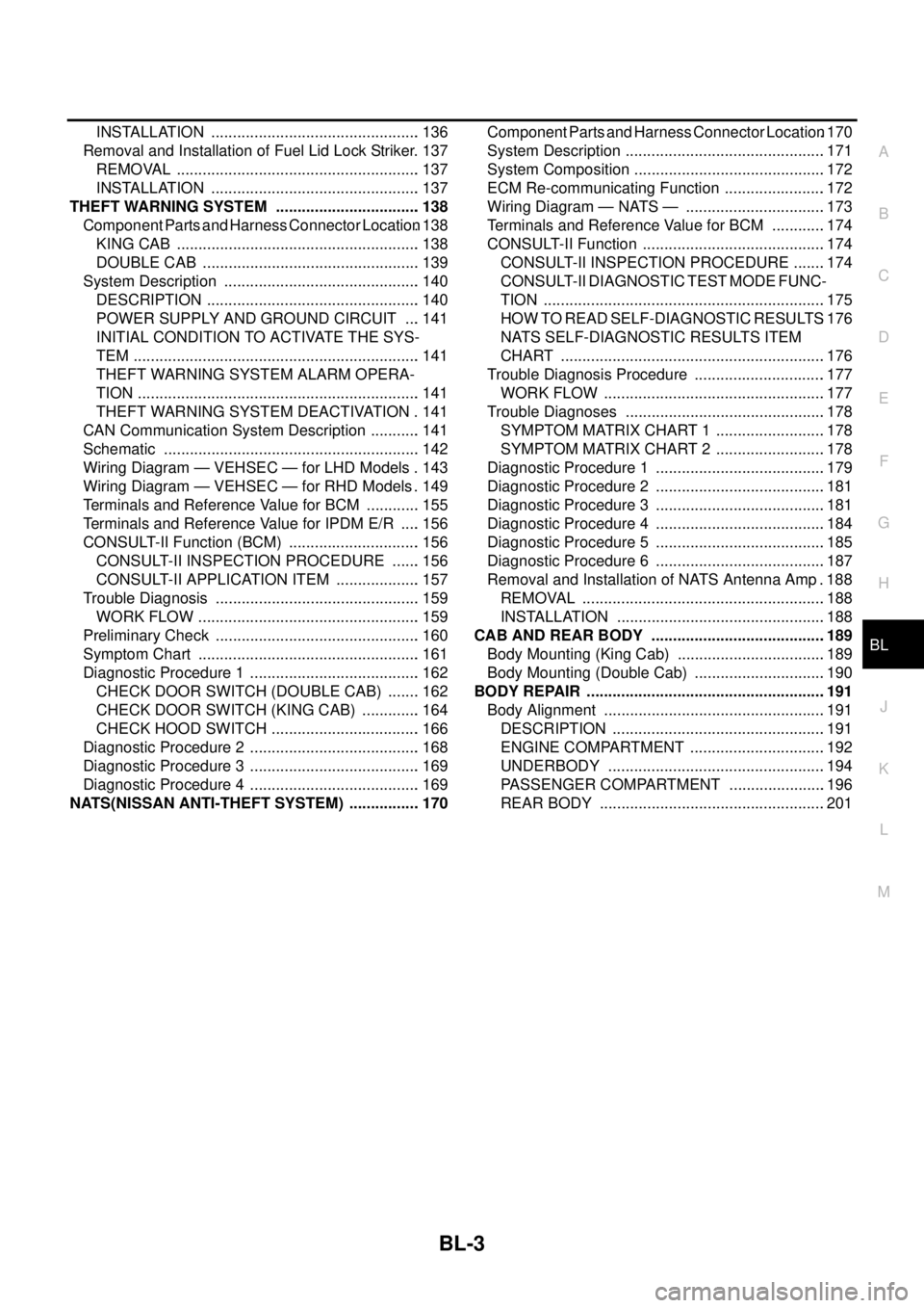
FUEL FILLER LID OPENER ...................................136
Removal and Installation of Fuel Filler Lid ............136
REMOVAL ..........................................................136
Page 587 of 3171
BL-3
C
D
E
F
G
H
J
K
L
MA
B
BL INSTALLATION ................................................. 136
Removal and Installation of Fuel Lid Lock Striker. 137
REMOVAL ......................................................... 137
INSTALLATION ................................................. 137
THEFT WARNING SYSTEM .................................. 138
Component Parts and Harness Connector Location. 138
KING CAB ......................................................... 138
DOUBLE CAB ................................................... 139
System Description .............................................. 140
DESCRIPTION .................................................. 140
POWER SUPPLY AND GROUND CIRCUIT .... 141
INITIAL CONDITION TO ACTIVATE THE SYS-
TEM ................................................................... 141
THEFT WARNING SYSTEM ALARM OPERA-
TION .................................................................. 141
THEFT WARNING SYSTEM DEACTIVATION . 141
CAN Communication System Description ............ 141
Schematic ............................................................ 142
Wiring Diagram — VEHSEC — for LHD Models . 143
Wiring Diagram — VEHSEC — for RHD Models . 149
Terminals and Reference Value for BCM ............. 155
Terminals and Reference Value for IPDM E/R ..... 156
CONSULT-II Function (BCM) ............................... 156
CONSULT-II INSPECTION PROCEDURE ....... 156
CONSULT-II APPLICATION ITEM .................... 157
Trouble Diagnosis ................................................ 159
WORK FLOW .................................................... 159
Preliminary Check ................................................ 160
Symptom Chart .................................................... 161
Diagnostic Procedure 1 ........................................ 162
CHECK DOOR SWITCH (DOUBLE CAB) ........ 162
CHECK DOOR SWITCH (KING CAB) .............. 164
CHECK HOOD SWITCH ................................... 166
Diagnostic Procedure 2 ........................................ 168
Diagnostic Procedure 3 ........................................ 169
Diagnostic Procedure 4 ........................................ 169
NATS(NISSAN ANTI-THEFT SYSTEM) ................. 170Component Parts and Harness Connector Location.170
System Description ...............................................171
System Composition .............................................172
ECM Re-communicating Function ........................172
Wiring Diagram — NATS — .................................173
Terminals and Reference Value for BCM .............174
CONSULT-II Function ...........................................174
CONSULT-II INSPECTION PROCEDURE ........174
CONSULT-II DIAGNOSTIC TEST MODE FUNC-
TION ..................................................................175
HOW TO READ SELF-DIAGNOSTIC RESULTS.176
NATS SELF-DIAGNOSTIC RESULTS ITEM
CHART ..............................................................176
Trouble Diagnosis Procedure ...............................177
WORK FLOW ....................................................177
Trouble Diagnoses ...............................................178
SYMPTOM MATRIX CHART 1 ..........................178
SYMPTOM MATRIX CHART 2 ..........................178
Diagnostic Procedure 1 ........................................179
Diagnostic Procedure 2 ........................................181
Diagnostic Procedure 3 ........................................181
Diagnostic Procedure 4 ........................................184
Diagnostic Procedure 5 ........................................185
Diagnostic Procedure 6 ........................................187
Removal and Installation of NATS Antenna Amp . 188
REMOVAL .........................................................188
INSTALLATION .................................................188
CAB AND REAR BODY .........................................189
Body Mounting (King Cab) ...................................189
Body Mounting (Double Cab) ...............................190
BODY REPAIR ........................................................191
Body Alignment ....................................................191
DESCRIPTION ..................................................191
ENGINE COMPARTMENT ................................192
UNDERBODY ...................................................194
PASSENGER COMPARTMENT .......................196
REAR BODY .....................................................201
Page 720 of 3171
BL-136
FUEL FILLER LID OPENER
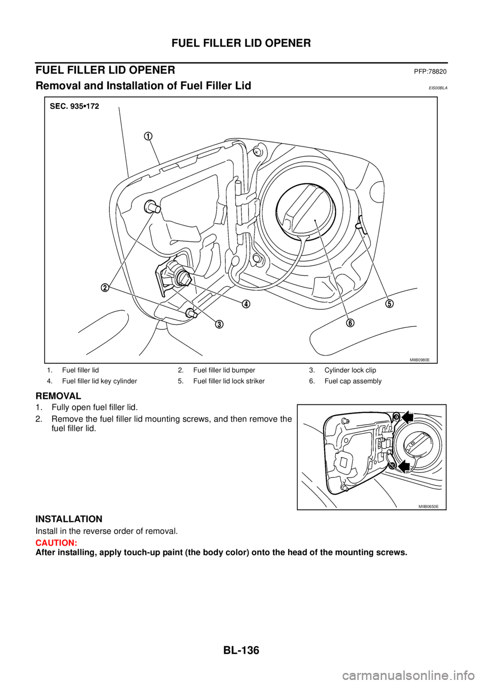
FUEL FILLER LID OPENER
PFP:78820
Removal and Installation of Fuel Filler LidEIS00BLA
REMOVAL
1. Fully open fuel filler lid.
2. Remove the fuel filler lid mounting screws, and then remove the
fuel filler lid.
INSTALLATION
Install in the reverse order of removal.
CAUTION:
After installing, apply touch-up paint (the body color) onto the head of the mounting screws.
1. Fuel filler lid 2. Fuel filler lid bumper 3. Cylinder lock clip
4. Fuel filler lid key cylinder 5. Fuel filler lid lock striker 6. Fuel cap assembly
MIIB0980E
MIIB0650E
Page 721 of 3171
FUEL FILLER LID OPENER
BL-137
C
D
E
F
G
H
J
K
L
MA
B
BL
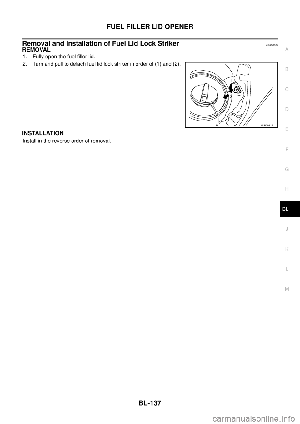
Removal and Installation of Fuel Lid Lock StrikerEIS00BQ0
REMOVAL
1. Fully open the fuel filler lid.
2. Turn and pull to detach fuel lid lock striker in order of (1) and (2).
INSTALLATION
Install in the reverse order of removal.
MIIB0981E