Page 523 of 3171

TERMINALS AND REFERENCE VALUE FOR CONTROL UNIT
AV-35
C
D
E
F
G
H
I
J
L
MA
B
AV
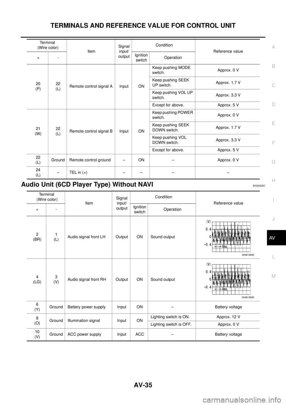
Audio Unit (6CD Player Type) Without NAVIEKS00Q6C
20
(P)22
(L)Remote control signal A Input ONKeep pushing MODE
switch.Approx. 0 V
Keep pushing SEEK
UP switch.Approx. 1.7 V
Keep pushing VOL UP
switch.Approx. 3.3 V
Except for above. Approx. 5 V
21
(W)22
(L)Remote control signal B Input ONKeep pushing POWER
switch.Approx. 0 V
Keep pushing SEEK
DOWN switch.Approx. 1.7 V
Keep pushing VOL
DOWN switch.Approx. 3.3 V
Except for above. Approx. 5 V
22
(L)Ground Remote control ground – ON – Approx. 0 V
24
(L)–TELin(+) – – – – Terminal
(Wire color)
ItemSignal
input/
outputCondition
Reference value
+-Ignition
switchOperation
Terminal
(Wire color)
ItemSignal
input/
outputCondition
Reference value
+-Ignition
switchOperation
2
(BR)1
(L)Audio signal front LH Output ON Sound output
4
(LG)3
(V)Audio signal front RH Output ON Sound output
6
(Y)Ground Battery power supply Input ON – Battery voltage
8
(O)Ground Illumination signal Input ONLighting switch is ON. Approx. 12 V
Lighting switch is OFF. Approx. 0 V
10
(V)Ground ACC power supply Input ACC – Battery voltage
SKIB1990E
SKIB1990E
Page 524 of 3171
AV-36
TERMINALS AND REFERENCE VALUE FOR CONTROL UNIT
14
(L)13
(V)Audio signal rear LH Output ON Sound output
16
(GR)15
(V)Audio signal rear RH Output ON Sound output
18
(W)GroundVehicle speed signal
(2-pulse)Input ONWhen vehicle speed is
approx. 40 km/h (25
MPH).
20
(SB)– Immobilizer – – – –
22
(P)25
(L)Remote control signal A Input ONKeep pushing MODE
switch.Approx. 0 V
Keep pushing SEEK UP
switch.Approx. 1.7 V
Keep pushing VOL UP
switch.Approx. 3.3 V
Except for above. Approx. 5 V
23
(W)25
(L)Remote control signal B Input ONKeep pushing POWER
switch.Approx. 0 V
Keep pushing SEEK
DOWN switch.Approx. 1.7 V
Keep pushing VOL
DOWN switch.Approx. 3.3 V
Except for above. Approx. 5V
25
(L)Ground Remote control ground – ON – Approx. 0 V
26
(W)–TELin(–) – – – –
27
(L)–TELin(+) – – – –
28
(Y)–TELmute – – – – Terminal
(Wire color)
ItemSignal
input/
outputCondition
Reference value
+-Ignition
switchOperation
SKIB1990E
SKIB1990E
ELF1080D
Page 525 of 3171

TERMINALS AND REFERENCE VALUE FOR CONTROL UNIT
AV-37
C
D
E
F
G
H
I
J
L
MA
B
AV
Audio Unit (With NAVI)EKS00Q6D
Terminal
(Wire color)
ItemSignal
input/
outputCondition
Reference value
+-Ignition
switchOperation
3
(Y)–Communication
signal (H)Input/
output–– –
4
(R)–Communication
signal (L)Input/
output–– –
10
(W)11
(O)TEL voice signal Input ON TEL voice output
12
(O)13
(W)Voice guidance signal Input ON Voice guidance output
17 Ground Shield (TEL voice) – ON – Approx. 0 V
18 Ground Shield (Guide voice) – ON – Approx. 0 V
22
(BR)23
(L)Audio signal front LH Output ON Sound output
24
(L)25
(V)Audio signal rear LH Output ON Sound output
26
(P)35
(L)Remote control signal A Input ONKeep pushing SOURCE
switch.approx. 0 V
Keep pushing MENU
UP switch.Approx. 1.2 V
Keep pushing MENU
DOWN switch.Approx. 2.5 V
Keep pushing ENTER
switch.Approx. 3.7 V
Except for above. Approx. 5 V
27
(V)Ground ACC power supply Input ACC – Battery voltage
28
(B)GroundIllumination control sig-
nalInput ONIllumination control
switch is operated by
lighting switch in ON
positionChanges between approx. 0 V
and approx. 12 V
SKIB1990E
SKIB1990E
SKIB1990E
SKIB1990E
Page 526 of 3171

AV-38
TERMINALS AND REFERENCE VALUE FOR CONTROL UNIT
NAVI Control Unit
EKS00Q6E
29
(O)Ground Illumination signal Input ONLighting switch is ON. Approx. 12 V
Lighting switch is OFF. Approx. 0 V
31
(LG)32
(V)Audio signal front RH Output ON Sound output
33
(GR)34
(V)Audio signal rear RH Output ON Sound output
36
(W)35
(L)Remote control signal B Input ONKeep pushing VOL
DOWN switch.Approx. 0 V
Keep pushing VOL UP
switch.Approx. 1.2 V
Keep pushing TEL, PTT
switch.Approx. 2.5 V
Keep pushing BACK
switch.Approx. 3.7 V
Except for above. Approx. 5 V
39
(Y)Ground Battery power supply Input ON – Battery voltage Terminal
(Wire color)
ItemSignal
input/
outputCondition
Reference value
+-Ignition
switchOperation
SKIB1990E
SKIB1990E
Terminal
(Wire color)
ItemSignal
input/
outputCondition
Reference value
+-Ignition
switchOperation
1
(B)Ground Ground – ON – Approx. 0 V
2
(Y)Ground Battery power supply Input ON – Battery voltage
5
(V)Ground ACC power supply Input ACC – Battery voltage
6
(B)Ground MIC. power supply Output ON – Approx. 5 V
7 Ground Shield (MIC.) – ON – Approx. 0 V
8
(W)Ground MIC. signal Input ON Sounds
9 Ground Shield (TEL voice) – ON – Approx. 0 V
PKIB5037J
Page 547 of 3171

DIAGNOSIS SYSTEM
AV-59
C
D
E
F
G
H
I
J
L
MA
B
AV
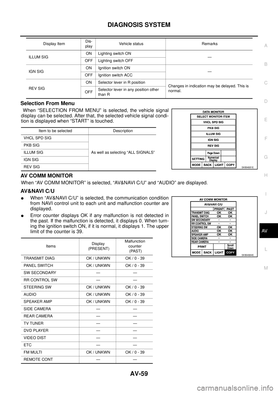
Selection From Menu
When “SELECTION FROM MENU” is selected, the vehicle signal
display can be selected. After that, the selected vehicle signal condi-
tion is displayed when “START” is touched.
AV C O M M M O N I T O R
When “AV COMM MONITOR” is selected, “AV&NAVI C/U” and “AUDIO” are displayed.
AV&NAVI C/U
lWhen “AV&NAVI C/U” is selected, the communication condition
from NAVI control unit to each unit and malfunction counter are
displayed.
lError counter displays OK if any malfunction is not detected in
the past. If the malfunction is detected, it displays 0. When turn-
ing the ignition switch ON, if it is normal, it displays 1. The upper
limitofthecounteris39.
ILLUM SIGON Lighting switch ON
—
OFF Lighting switch OFF
IGN SIGON Ignition switch ON
—
OFF Ignition switch ACC
REV SIGON Selector lever in R position
Changes in indication may be delayed. This is
normal.
OFFSelector lever in any position other
than R Display ItemDis-
playVehicle status Remarks
Item to be selected Description
VHCL SPD SIG
As well as selecting “ALL SIGNALS” PKB SIG
ILLUM SIG
IGN SIG
REV SIG
SKIB4681E
ItemsDisplay
(PRESENT)Malfunction
counter
(PAST)
TRANSMIT DIAG OK / UNKWN OK / 0 - 39
PANEL SWITCH OK / UNKWN OK / 0 - 39
SW SECONDARY — —
RR CONTROL SW — —
STEERING SW OK / UNKWN OK / 0 - 39
AUDIO OK / UNKWN OK / 0 - 39
SPEAKER AMP OK / UNKWN OK / 0 - 39
SIDE CAMERA — —
REAR CAMERA — —
TV TUNER — —
DVD PLAYER — —
VIDEO DIST — —
ETC — —
FM MULTI OK / UNKWN OK / 0 - 39
REMOTE CONT — —
SKIB4684E
Page 550 of 3171

AV-62
TROUBLE DIAGNOSIS
Voice Activated Control System
EKS00Q6Q
Symptoms Check items Probable malfunction location
The voice cannot be controlled
even if the voice control screen is
displayedVoice sounds at “Speaker Test” and
“Voice Microphone Test” of Confir-
mation/Adjustment modeNAVI control unit
Voice does not sound at “Speaker
Test” and “Voice Microphone Test” of
Confirmation/Adjustment mode
lMIC. power supply circuit
lShield (MIC.) circuit
lMIC. signal circuit
lMicrophone
lNAVI control unit
The voice cannot be controlled
(Voice control screen is not dis-
played)TEL operation screen is displayed by
pressing and holding “TEL/PPT”
switch of steering wheel switchNAVI control unit
lTEL operation screen is not dis-
played by pressing and holding
“TEL/PPT” switch of steering
wheel switch
lOther steering wheel switches are
normalSteering wheel switch
“BACK”, “VOL UP”, “VOL DOWN”,
and “TEL/PPT” switches of steering
wheel switch are not operated
lRemote control signal B circuit
lSteering wheel switch
lAudio unit
All steering wheel switches are not
operated
lRemote control signal ground circuit
lSteering wheel switch
lAudio unit
Page 551 of 3171

TROUBLE DIAGNOSIS
AV-63
C
D
E
F
G
H
I
J
L
MA
B
AV
Steering Wheel SwitchEKS00Q6R
Without NAVI
With NAVI
Component Parts InspectionEKS00Q6S
STEERING WHEEL SWITCH UNIT INSPECTION
lCheck continuity between combination switch harness connector M302 terminal 15 and terminal 16.
lCheck continuity between combination switch harness connector M302 terminal 14 and terminal 16.
Symptoms Probable malfunction location
All steering wheel switches are not operated
lRemote control signal ground circuit
lSteering wheel switch
lAudio unit
Only specified switch cannot be operated Steering wheel switch
“MODE”, “SEEK UP”, and “VOL UP” switches are not oper-
ated
lRemote control signal A circuit
lSteering wheel switch
lAudio unit
“SEEK DOWN”, and “VOL DOWN” switches are not oper-
ated
lRemote control signal B circuit
lSteering wheel switch
lAudio unit
Symptoms Probable malfunction location
All steering wheel switches are not operated
lRemote control signal ground circuit
lSteering wheel switch
lAudio unit
Only specified switch cannot be operated Steering wheel switch
“ENTER”, “MENU UP”, “MENU DOWN”, and “SOURCE”
switches are not operated
lRemote control signal A circuit
lSteering wheel switch
lAudio unit
“BACK”, “TEL /PPT”, “VOL UP”, and “VOL DOWN” switches
are not operated
lRemote control signal B circuit
lSteering wheel switch
lAudio unit
Page 574 of 3171

BCS-8
BCM (BODY CONTROL MODULE)
SYSTEMS CONTROLLED BY BCM DIRECTLY
NOTE:
Power supply only. No system control.
SYSTEMS CONTROLLED BY BCM AND IPDM E/R
SYSTEMS CONTROLLED BY BCM AND COMBINATION METER
System Reference
Power door lock
lBL-21, "POWER DOOR LOCK SYSTEM"
lBL-55, "POWER DOOR LOCK—SUPER LOCK—"
Remote keyless entryBL-89, "MULTI-REMOTE CONTROL SYSTEM"
Power windowNOTEGW-15, "POWER WINDOW SYSTEM"
Sunroof systemNOTERF-10, "SUNROOF"
Room lamp timerLT-145, "INTERIOR ROOM LAMP"
Rear fog lampLT- 8 7 , "REAR FOG LAMP"
System Reference
NATSBL-170, "
NATS(Nissan Anti-Theft System)"
HeadlampLT- 5 , "HEADLAMP -CONVENTIONAL TYPE-"
Daytime light systemLT-31, "HEADLAMP - DAYTIME LIGHT SYSTEM -"
Auto light systemLT-49, "AUTO LIGHT SYSTEM"
Parking, license plate and tail lampsLT-125, "PARKING, LICENSE PLATE AND TAIL LAMPS"
Front fog lampLT-71, "FRONT FOG LAMP"
Front wiper, washerWW-4, "FRONT WIPER AND WASHER SYSTEM"
Headlamp washerWW-39, "HEADLAMP WASHER"
Rear window defoggerGW-47, "REAR WINDOW DEFOGGER"
System Reference
Warning chimeDI-51, "
WARNING CHIME"
Turn signal and hazard warning lampsLT-97, "TURN SIGNAL AND HAZARD WARNING LAMPS"