2005 NISSAN NAVARA ECO mode
[x] Cancel search: ECO modePage 1 of 3171

MODELD40 SERIES
2005 NISSAN EUROPE S.A.S.
All rights reserved. No part of this Electronic Service Manual may be reproduced or stored in a retrieval system, or transmitted in any
form, or by any means, electronic, mechanical, photocopying, recording or otherwise, without the prior written permission of Nissan
Europe S.A.S., Paris, France.
A GENERAL INFORMATION
B ENGINE
C TRANSMISSION/TRANSAXLE
D DRIVELINE/AXLE
E SUSPENSION F BRAKES
G STEERING H RESTRAINTS
I BODY
J AIR CONDITIONER
K ELECTRICAL
L MAINTENANCE
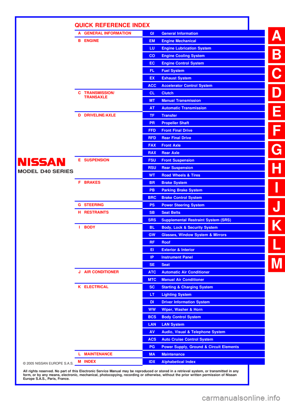
M INDEXGI General Information
EM Engine Mechanical
LU Engine Lubrication System
CO Engine Cooling System
EC Engine Control System
FL Fuel System
EX Exhaust System
ACC Accelerator Control System
CL Clutch
MTManualTransmission
AT Automatic Transmission
TF Transfer
PR Propeller Shaft
FFD Front Final Drive
RFD Rear Final Drive
FAX Front Axle
RAX Rear Axle
FSU Front Suspension
RSU Rear Suspension
WT Road Wheels & Tires
BR Brake System
PB Parking Brake System
BRC Brake Control System
PS Power Steering System
SB Seat Belts
SRS Supplemental Restraint System (SRS)
BL Body, Lock & Security System
GW Glasses, Window System & Mirrors
RF Roof
EI Exterior & Interior
IP Instrument Panel
SE Seat
ATC Automatic Air Conditioner
MTC Manual Air Conditioner
SC Starting & Charging System
LT Lighting System
DI Driver Information System
WW Wiper, Washer & Horn
BCS Body Control System
LAN LAN System
AV Audio, Visual & Telephone System
ACS Auto Cruise Control System
PG Power Supply, Ground & Circuit Elements
MA Maintenance
IDX Alphabetical Index
QUICK REFERENCE INDEX
A
B
C
D
E
F
G
H
I
J
K
L
M
Page 2 of 3171

FOREWORD
This manual contains maintenance and repair procedures for the NISSAN
NAVARA,modelD40 series.
In order to assure your safety and the efficient functioning of the vehicle,
this manual should be read thoroughly. It is especially important that the
PRECAUTIONS in the GI section be completely understood before starting
any repair task.
All information in this manual is based on the latest product information
at the time of publication. The right is reserved to make changes in speci-
fications and methods at any time without notice.
IMPORTANT SAFETY NOTICE
The proper performance of service is essential for both the safety of the
technician and the efficient functioning of the vehicle.
The service methods in this Service Manual are described in such a man-
ner that the service may be performed safely and accurately.
Service varies with the procedures used, the skills of the technician and the
tools and parts available. Accordingly, anyone using service procedures,
tools or parts which are not specifically recommended by NISSAN must
first be completely satisfied that neither personal safety nor the vehicle's
safety will be jeopardized by the service method selected.
NISSAN EUROPE S.A.S.
Service Engineering SectionParis, France
Page 42 of 3171

AT-34
TROUBLE DIAGNOSIS
TROUBLE DIAGNOSIS
PFP:00004
DTC Inspection Priority ChartECS00FWV
If some DTCs are displayed at the same time, perform inspections one by one based on the following priority
chart.
NOTE:
If DTC “U1000 CAN COMM CIRCUIT” is displayed with other DTCs, first perform the trouble diagnosis
for “DTC U1000 CAN COMMUNICATION LINE”. Refer toAT-91
.
Fail-safeECS00FWW
The TCM has an electrical fail-safe mode. This mode makes it possible to operate even if there is an error in a
main electronic control input/output signal circuit. In fail-safe mode A/T is fixed in 2nd, 4th or 5th (depending
on the breakdown position), so the customer should feel “slipping” or “poor acceleration”.
Even when the electronic circuits are normal, under special conditions (for example, when slamming on the
brake with the wheels spinning drastically and stopping the tire rotation), the transmission can go into fail-safe
mode. If this happens, switch OFF the ignition switch for 10 seconds, then switch it ON again to return to the
normal shift pattern. Therefore, the customer's vehicle has returned to normal, so handle according toAT- 3 7 ,
"WORK FLOW".
FAIL-SAFE FUNCTION
If any malfunction occurs in a sensor or solenoid, this function controls the A/T to mark driving possible.
Vehicle Speed Sensor
Signals are input from two systems - from vehicle speed sensor A/T (revolution sensor) installed on the A/T
and from combination meter so normal driving is possible even if there is a malfunction in one of the systems.
And if vehicle speed sensor A/T (revolution sensor) has unusual cases, 5th gear is prohibited.
Accelerator Pedal Position Sensor
If there is a malfunction in one of the systems, the accelerator opening angle is controlled by ECM according
to a pre-determined accelerator angle to make driving possible. And if there are malfunctions in tow systems,
the engine speed is fixed by ECM to a pre-determined engine speed to make driving possible.
PNP Switch
In the unlikely event that a malfunction signal enters the TCM, the position indicator is switched OFF, the
starter relay is switched OFF (starter starting is disabled), the back-up lamp relay switched OFF (back-up lamp
is OFF) and the position is fixed to the “D” position to make driving possible.
Starter Relay
The starter relay is switched OFF. (Starter starting is disabled.)
Priority Detected items (DTC)
1 U1000 CAN communication line
2 Except above
Page 54 of 3171

AT-46
TROUBLE DIAGNOSIS
ROAD TEST
Description
lThe road test inspects overall performance of A/T and analyzes possible malfunction causes.
lThe road test is perform in the following three stages.
1. Check before engine is started. Refer toAT-46
.
2. Check at idle. Refer toAT-47
.
3. Cruise test.
lInspect all the items from Part 1 to Part 3. Refer toAT-48,AT-50,AT-51.
lBefore beginning the road test, check the test procedure and inspection items.
lTest all inspection items until the symptom is uncovered. Diagnose NG items when all road tests are com-
plete.
CheckBeforeEngineIsStartedECS00FX1
1.CHECK OD OFF INDICATOR LAMP
1. Park vehicle on level surface.
2. Move selector lever to “P” position.
3. Turn ignition switch OFF and wait at least 10 seconds.
4. Turn ignition switch ON. (Do not start engine.)
Does OD OFF indicator lamp light up for about 2 seconds?
YES >> 1. Turn ignition switch OFF.
2. Perform self-diagnosis and record all NG items onAT-38, "
DIAGNOSTIC WORKSHEET".
Refer toAT-80, "
SELF-DIAGNOSTIC RESULT MODE",AT-89, "TCM SELF-DIAGNOSTIC
PROCEDURE (WITHOUT CONSULT-II)".
3. Go toAT-47, "
Check at Idle".
NO >> Stop the road test and go toAT- 1 7 7 , "
OD OFF Indicator Lamp Does Not Come On".
Stall speedOil pressure does not
rise higher than the oil
pressure for idle.Possible causes include a sensor malfunction or malfunction in the pressure adjustment
function.
For example
lAccelerator pedal position signal malfunction
lTCM malfunction
lLine pressure solenoid malfunction (shorting, sticking in ON state)
lPressure regulator valve or plug sticking
lPilot valve sticking or pilot filter clogged
The pressure rises, but
does not enter the stan-
dard position.Possible causes include malfunctions in the pressure supply system and malfunction in the
pressure adjustment function.
For example
lAccelerator pedal position signal malfunction
lLine pressure solenoid malfunction (sticking, filter clog)
lPressure regulator valve or plug sticking
lPilot valve sticking or pilot filter clogged
Only low for a specific
positionPossible causes include an oil pressure leak in a passage or device related to the position
after the pressure is distributed by the manual valve. Judgement Possible cause
Page 56 of 3171

AT-48
TROUBLE DIAGNOSIS
6.CHECK “R” POSITION FUNCTIONS
1. Engage the brake.
2. Move selector lever to “R” position.
3. Release the brake for 4 to 5 seconds.
Does the vehicle creep backward?
YES >> GO TO 7.
NO >> Enter a check mark at “Vehicle Does Not Creep Backward in “R” Position” onAT-38, "
DIAGNOS-
TIC WORKSHEET", then continue the road test.
7.CHECK “D” POSITION FUNCTIONS
Inspect whether the vehicle creep forward when the A/T is put into the “D” position.
Does the vehicle creep forward in
“D”position?
YES >> Go toAT-48, "Cruise Test - Part 1",AT-50, "Cruise Test - Part 2"andAT-51, "Cruise Test - Part 3"
.
NO >> Enter a check mark at “Vehicle Does Not Creep Forward in “D” Position” onAT-38, "
DIAGNOSTIC
WORKSHEET", then continue the road test. Go toAT-48, "Cruise Test - Part 1",AT-50, "Cruise
Te s t - P a r t 2"andAT-51, "Cruise Test - Part 3".
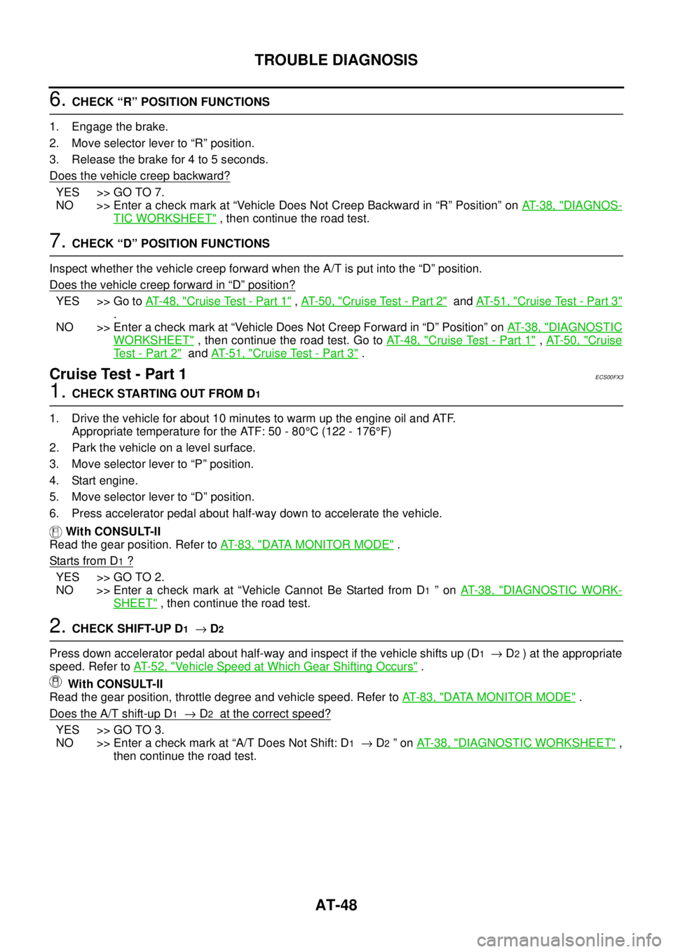
CruiseTest-Part1ECS00FX3
1.CHECK STARTING OUT FROM D1
1. Drive the vehicle for about 10 minutes to warm up the engine oil and ATF.
Appropriate temperature for the ATF: 50 - 80°C (122 - 176°F)
2. Park the vehicle on a level surface.
3. Move selector lever to “P” position.
4. Start engine.
5. Move selector lever to “D” position.
6. Press accelerator pedal about half-way down to accelerate the vehicle.
With CONSULT-II
Read the gear position. Refer toAT-83, "
DATA MONITOR MODE".
Starts from D
1?
YES >> GO TO 2.
NO >> Enter a check mark at “Vehicle Cannot Be Started from D
1”onAT-38, "DIAGNOSTIC WORK-
SHEET", then continue the road test.
2.CHECK SHIFT-UP D1®D2
Press down accelerator pedal about half-way and inspect if the vehicle shifts up (D1®D2) at the appropriate
speed. Refer toAT-52, "
Vehicle Speed at Which Gear Shifting Occurs".
With CONSULT-II
Read the gear position, throttle degree and vehicle speed. Refer toAT-83, "
DATA MONITOR MODE".
Does the A/T shift-up D
1®D2at the correct speed?
YES >> GO TO 3.
NO >> Enter a check mark at “A/T Does Not Shift: D
1®D2”onAT-38, "DIAGNOSTIC WORKSHEET",
then continue the road test.
Page 58 of 3171

AT-50
TROUBLE DIAGNOSIS
8.CHECK LOCK-UP RELEASE
Check lock-up cancellation by depressing brake pedal lightly to decelerate.
With CONSULT-II
Select “TCC SOLENOID” with “MAIN SIGNALS” mode for “A/T”. Refer toAT-77, "
CONSULT-II REFERENCE
VA L U E".
Does lock-up cancel?
YES >> GO TO 9.
NO >> Enter a check mark at “Lock-up Is Not Released” onAT-38, "
DIAGNOSTIC WORKSHEET",then
continue the road test.
9.CHECK SHIFT-DOWN D5®D4
Decelerate by pressing lightly on brake pedal.
With CONSULT-II
Read the gear position and engine speed. Refer toAT-83, "
DATA MONITOR MODE".
When the A/T shift-down D
5®D4, does the engine speed drop smoothly back to idle?
YES >> 1. Stop the vehicle.
2. Go toAT-50, "
Cruise Test - Part 2".
NO >> Enter a check mark at “Engine Speed Does Not Return to Idle” onAT-38, "
DIAGNOSTIC WORK-
SHEET", then continue the road test. Go toAT-50, "Cruise Test - Part 2".
CruiseTest-Part2ECS00FX4
1.CHECK STARTING FROM D1
1. Move selector lever to “D” position.
2. Accelerate at half throttle.
With CONSULT-II
Read the gear position. Refer toAT-83, "
DATA MONITOR MODE".
Does it start from D
1?
YES >> GO TO 2.
NO >> Enter a check mark at “Vehicle Cannot Be Started from D
1”onAT-38, "DIAGNOSTIC WORK-
SHEET", then continue the road test.
2.CHECK SHIFT-UP D1®D2
Press accelerator pedal down all the way and inspect whether or not the A/T shifts up (D1®D2)atthecor-
rect speed. Refer toAT-52, "
Vehicle Speed at Which Gear Shifting Occurs".
With CONSULT-II
Read the gear position, throttle degree and vehicle speed. Refer toAT-83, "
DATA MONITOR MODE".
Does the A/T shift-up D
1®D2at the correct speed?
YES >> GO TO 3.
NO >> Enter a check mark at “A/T Does Not Shift: D
1®D2”onAT-38, "DIAGNOSTIC WORKSHEET",
then continue the road test.
3.CHECK SHIFT-UP D2®D3
Press accelerator pedal down all the way and inspect whether or not the A/T shifts up (D2®D3)atthecor-
rect speed. Refer toAT-52, "
Vehicle Speed at Which Gear Shifting Occurs".
With CONSULT-II
Read the gear position, throttle degree and vehicle speed. Refer toAT-83, "
DATA MONITOR MODE".
Does the A/T shift-up D
2®D3at the correct speed?
YES >> GO TO 4.
NO >> Enter a check mark at “A/T Does Not Shift: D
2®D3”onAT-38, "DIAGNOSTIC WORKSHEET",
then continue the road test.
Page 91 of 3171

TROUBLE DIAGNOSIS
AT-83
D
E
F
G
H
I
J
K
L
MA
B
AT
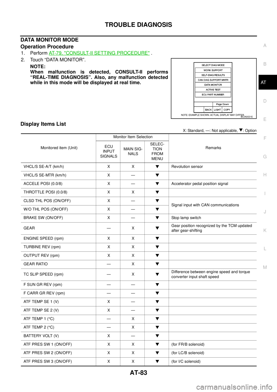
DATA MONITOR MODE
Operation Procedure
1. PerformAT-79, "CONSULT-II SETTING PROCEDURE".
2. Touch “DATA MONITOR”.
NOTE:
When malfunction is detected, CONSULT-II performs
“REAL-TIME DIAGNOSIS”. Also, any malfunction detected
while in this mode will be displayed at real time.
Display Items List
X: Standard, —: Not applicable, : Option
BCIA0031E
Monitored item (Unit)Monitor Item Selection
Remarks ECU
INPUT
SIGNALSMAIN SIG-
NALSSELEC-
TION
FROM
MENU
VHCL/S SE-A/T (km/h) X X Revolution sensor
VHCL/S SE-MTR (km/h) X —
ACCELE POSI (0.0/8) X — Accelerator pedal position signal
THROTTLE POSI (0.0/8) X X
CLSD THL POS (ON/OFF) X —
Signal input with CAN communications
W/O THL POS (ON/OFF) X —
BRAKE SW (ON/OFF) X — Stop lamp switch
GEAR — XGear position recognized by the TCM updated
after gear-shifting
ENGINE SPEED (rpm) X X
TURBINE REV (rpm) X X
OUTPUT REV (rpm) X X
GEAR RATIO — X
TC SLIP SPEED (rpm) — XDifference between engine speed and torque
converter input shaft speed
F SUN GR REV (rpm) — —
F CARR GR REV (rpm) — —
ATFTEMPSE1(V) X —
ATFTEMPSE2(V) X —
AT F T E M P 1 (°C) — X
AT F T E M P 2 (°C) — X
BATTERY VOLT (V) X —
ATF PRES SW 1 (ON/OFF) X X (for FR/B solenoid)
ATF PRES SW 2 (ON/OFF) X X (for LC/B solenoid)
ATF PRES SW 3 (ON/OFF) X X (for I/C solenoid)
Page 92 of 3171

AT-84
TROUBLE DIAGNOSIS
ATF PRES SW 5 (ON/OFF) X X (for D/C solenoid)
ATF PRES SW 6 (ON/OFF) X X (for HLR/C solenoid)
PNP SW 1 (ON/OFF) X —
PNP SW 2 (ON/OFF) X —
PNP SW 3 (ON/OFF) X —
PNP SW 4 (ON/OFF) X —
1 POSITION SW (ON/OFF) X — 1st position switch
SLCT LVR POSI — XSelector lever position is recognized by TCM.
For fail-safe operation, the specific value used
for control is displayed.
OD CONT SW (ON/OFF) X —
POWERSHIFT SW (ON/OFF) X —
Not mounted but displayed. HOLD SW (ON/OFF) X —
MANU MODE SW (ON/OFF) X —
NON M-MODE SW (ON/OFF) X —
UP SW LEVER (ON/OFF) X —
DOWN SW LEVER (ON/OFF) X —
SFTUPSTSW(ON/OFF) — —
SFT DWN ST SW (ON/OFF) — —
ASCD-OD CUT (ON/OFF) — —
ASCD-CRUISE (ON/OFF) — —
ABS SIGNAL (ON/OFF) — —
ACC OD CUT (ON/OFF) — —
Not mounted but displayed.
ACC SIGNAL (ON/OFF) — —
TCS GR/P KEEP (ON/OFF) — —
TCS SIGNAL 2 (ON/OFF) — —
TCS SIGNAL 1 (ON/OFF) — —
TCC SOLENOID (A) — X
LINE PRES SOL (A) — X
I/C SOLENOID (A) — X
FR/B SOLENOID (A) — X
D/C SOLENOID (A) — X
HLR/C SOL (A) — X
ON OFF SOL (ON/OFF) — — LC/B solenoid
TCC SOL MON (A) — —
L/P SOL MON (A) — —Monitored item (Unit)Monitor Item Selection
Remarks ECU
INPUT
SIGNALSMAIN SIG-
NALSSELEC-
TION
FROM
MENU