2005 NISSAN NAVARA seat adjustment
[x] Cancel search: seat adjustmentPage 2684 of 3171

SQUEAK AND RATTLE TROUBLE DIAGNOSES
RF-7
C
D
E
F
G
H
J
K
L
MA
B
RF
TRUNK
Trunk noises are often caused by a loose jack or loose items put into the trunk by the owner.
In addition look for:
1. Trunk lid dumpers out of adjustment
2. Trunk lid striker out of adjustment
3. Trunk lid torsion bars knocking together
4. A loose license plate or bracket
Most of these incidents can be repaired by adjusting, securing or insulating the item(s) or component(s) caus-
ing the noise.
SUNROOF/HEADLINING
Noises in the sunroof/headlining area can often be traced to one of the following:
1. Sunroof lid, rail, linkage or seals making a rattle or light knocking noise
2. Sunvisor shaft shaking in the holder
3. Front or rear windshield touching headlining and squeaking
Again, pressing on the components to stop the noise while duplicating the conditions can isolate most of these
incidents. Repairs usually consist of insulating with felt cloth tape.
SEATS
When isolating seat noise it's important to note the position the seat is in and the load placed on the seat when
the noise is present. These conditions should be duplicated when verifying and isolating the cause of the
noise.
Cause of seat noise include:
1. Headrest rods and holder
2. A squeak between the seat pad cushion and frame
3. Rear seatback lock and bracket
These noises can be isolated by moving or pressing on the suspected components while duplicating the con-
ditions under which the noise occurs. Most of these incidents can be repaired by repositioning the component
or applying urethane tape to the contact area.
UNDERHOOD
Some interior noise may be caused by components under the hood or on the engine wall. The noise is then
transmitted into the passenger compartment.
Causes of transmitted underhood noise include:
1. Any component mounted to the engine wall
2. Components that pass through the engine wall
3. Engine wall mounts and connectors
4. Loose radiator mounting pins
5. Hood bumpers out of adjustment
6. Hood striker out of adjustment
These noises can be difficult to isolate since they cannot be reached from the interior of the vehicle. The best
method is to secure, move or insulate one component at a time and test drive the vehicle. Also, engine RPM
or load can be changed to isolate the noise. Repairs can usually be made by moving, adjusting, securing, or
insulating the component causing the noise.
Page 2699 of 3171

RF-22
SUNROOF
lAfter any adjustment, check sunroof operation and glass lid alignment.
lHandle glass lid with care so not to cause damage.
lFor easier installation, mark each point before removal.
CAUTION:
lAlways work with a helper.
lBefore removal, fully close the glass lid assembly. Then, after removal, do not move the motor
assembly.
lAfter installing the sunroof and glass lid, check gap adjustment to ensure there is no malfunction.
SUNROOF UNIT
Removal
CAUTION:
lAlways work with a helper.
lWhen taking sunroof unit out, use shop cloths to protect the seats and trim from damage.
lAfter installing the sunroof unit and glass lid, be sure to check gap adjustment to ensure there is
no malfunction.
1. Remove headlining. Refer toEI-40, "
Removal and Installation".
2. Remove the sunroof glass lid. Refer toRF-22, "
GLASS LID".
3. Disconnect the drain hoses.
4. Remove the mounting nuts from the front end and side rail.
5. Remove the mounting bolts to sunroof bracket and then remove the sunroof unit.
Installation
1. Position the sunroof frame assembly and temporally tighten the mounting bolts to the sunroof brackets.
2. Tighten the mounting nuts to the front end and side rail.
3. Tighten the mounting bolts to sunroof brackets.
4. Connect the drain hoses.
5. Install the sunroof glass lid. Refer toRF-22, "
GLASS LID".
6. Install headlining. Refer toEI-40, "
Removal and Installation".
GLASS LID
Removal
1. Open sunshade.
2. Ensure glass lid is closed.
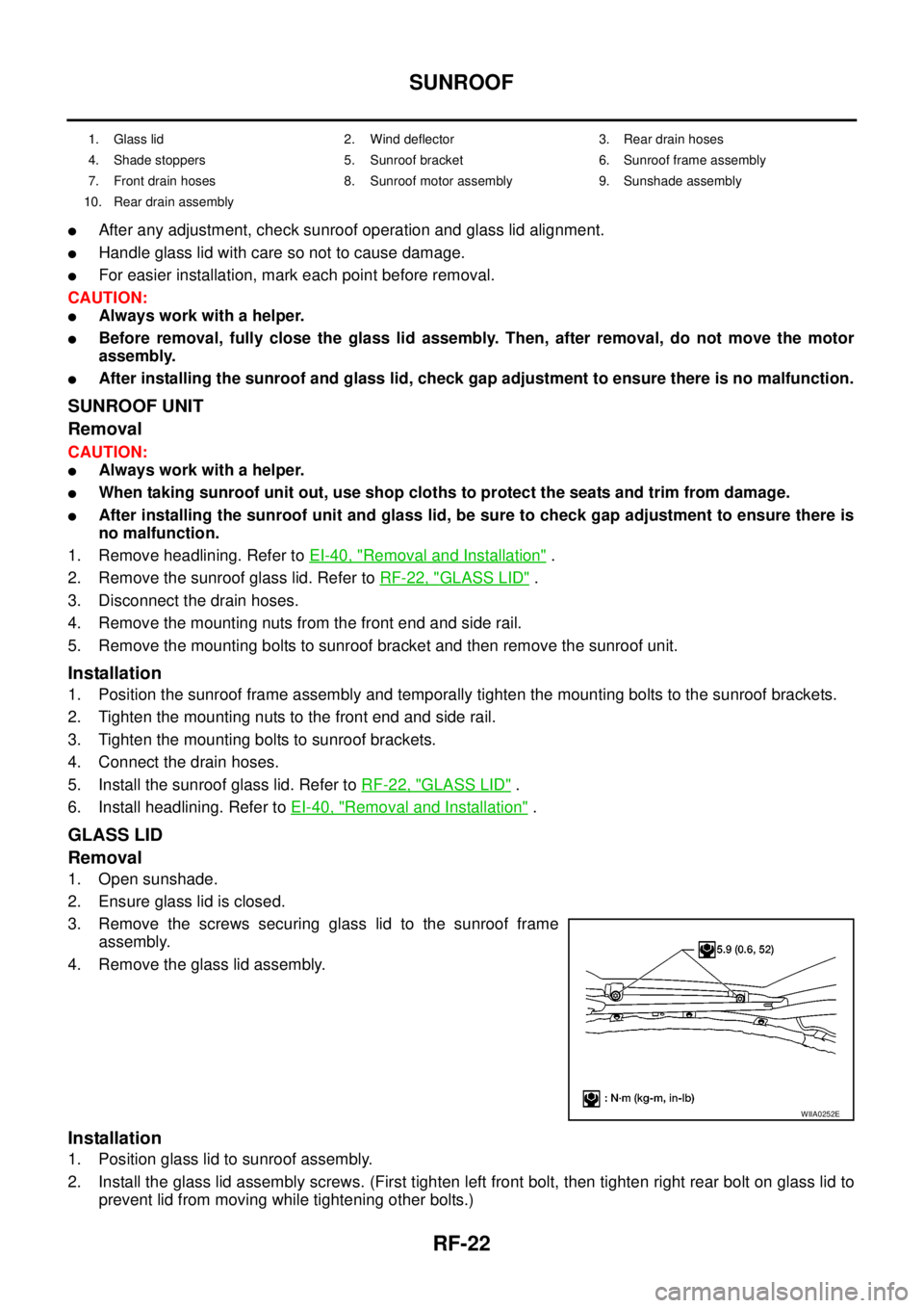
3. Remove the screws securing glass lid to the sunroof frame
assembly.
4. Remove the glass lid assembly.
Installation
1. Position glass lid to sunroof assembly.
2. Install the glass lid assembly screws. (First tighten left front bolt, then tighten right rear bolt on glass lid to
prevent lid from moving while tightening other bolts.)
1. Glass lid 2. Wind deflector 3. Rear drain hoses
4. Shade stoppers 5. Sunroof bracket 6. Sunroof frame assembly
7. Front drain hoses 8. Sunroof motor assembly 9. Sunshade assembly
10. Rear drain assembly
WIIA0252E
Page 2704 of 3171

RFD-1
REAR FINAL DRIVE
D DRIVELINE/AXLE
CONTENTS
C
E
F
G
H
I
J
K
L
M
SECTIONRFD
A
B
RFD
REAR FINAL DRIVE
WITH LIMITED SLIP DIFFERENTIAL
PRECAUTIONS .......................................................... 3
Limited Slip Differential (LSD) Performance Judge-
ment ......................................................................... 3
METHOD FOR TROUBLESHOOTING ................. 3
Service Notice or Precautions .................................. 3
PREPARATION ........................................................... 4
Special Service Tools ............................................... 4
Commercial Service Tools ........................................ 5
NOISE, VIBRATION, AND HARSHNESS (NVH)
TROUBLESHOOTING ................................................ 7
NVH Troubleshooting Chart ..................................... 7
DESCRIPTION ............................................................ 8
Cross-Sectional View ............................................... 8
DIFFERENTIAL GEAR OIL ........................................ 9
Changing Differential Gear Oil ................................. 9
DRAINING ............................................................. 9
FILLING ................................................................. 9
Checking Differential Gear Oil .................................. 9
OIL LEAKAGE AND OIL LEVEL ........................... 9
FRONT OIL SEAL .................................................... 10
Removal and Installation ........................................ 10
REMOVAL ........................................................... 10
INSTALLATION .................................................... 11
CARRIER COVER .................................................... 13
Removal and Installation ........................................ 13
REMOVAL ........................................................... 13
INSTALLATION ................................................... 13
REAR FINAL DRIVE ASSEMBLY ............................ 14
Removal and Installation ........................................ 14
REMOVAL ........................................................... 14
INSTALLATION ................................................... 14
Disassembly and Assembly ................................... 15
COMPONENTS .................................................. 15
ASSEMBLY INSPECTION AND ADJUSTMENT... 16
DISASSEMBLY ................................................... 19
INSPECTION AFTER DISASSEMBLY ............... 22
SELECTION ADJUSTING WASHERS ............... 23
ASSEMBLY ......................................................... 24SERVICE DATA AND SPECIFICATIONS (SDS) ...... 31
General Specifications ............................................ 31
Inspection and Adjustment ..................................... 31
PRELOAD TORQUE ........................................... 31
BACKLASH ......................................................... 31
COMPANION FLANGE RUNOUT ....................... 31
SELECTIVE PARTS ............................................ 32
WITH ELECTRONIC LOCKING DIFFEREN-
TIAL
PRECAUTIONS ........................................................ 33
Precautions for Supplemental Restraint System
(SRS)“AIRBAG”and“SEATBELTPRE-TEN-
SIONER” ................................................................. 33
Precautions for Differential Case Assembly and Dif-
ferential Lock Control Unit Replacement ................ 33
CHECK DIFF LOCK INDICATOR LAMP ............. 33
METHOD FOR ADJUSTMENT ........................... 34
Precautions ............................................................. 34
Service Notice or Precaution .................................. 35
Wiring Diagrams and Trouble Diagnosis ................ 35
PREPARATION ......................................................... 36
Special Service Tools ............................................. 36
Commercial Service Tools ...................................... 37
NOISE, VIBRATION AND HARSHNESS (NVH)
TROUBLESHOOTING .............................................. 39
NVH Troubleshooting Chart ................................... 39
DIFFERENTIAL GEAR OIL ...................................... 40
Changing Differential Gear Oil ................................ 40
DRAINING ........................................................... 40
FILLING ............................................................... 40
Checking Differential Gear Oil ................................ 40
OIL LEAKAGE AND OIL LEVEL ......................... 40
DIFFERENTIAL LOCK SYSTEM .............................. 41
Cross-sectional View .............................................. 41
Differential Lock Operation ..................................... 42
System Description ................................................. 42
DIFFERENTIAL LOCK SOLENOID .................... 42
DIFFERENTIAL LOCK POSITION SWITCH ....... 42
Page 2728 of 3171
![NISSAN NAVARA 2005 Repair Workshop Manual REAR FINAL DRIVE ASSEMBLY
RFD-25
[WITH LIMITED SLIP DIFFERENTIAL]
C
E
F
G
H
I
J
K
L
MA
B
RFD
b. Insert companion flange onto drive pinion. Tap the companion
flange with a soft hammer until fully seate NISSAN NAVARA 2005 Repair Workshop Manual REAR FINAL DRIVE ASSEMBLY
RFD-25
[WITH LIMITED SLIP DIFFERENTIAL]
C
E
F
G
H
I
J
K
L
MA
B
RFD
b. Insert companion flange onto drive pinion. Tap the companion
flange with a soft hammer until fully seate](/manual-img/5/57362/w960_57362-2727.png)
REAR FINAL DRIVE ASSEMBLY
RFD-25
[WITH LIMITED SLIP DIFFERENTIAL]
C
E
F
G
H
I
J
K
L
MA
B
RFD
b. Insert companion flange onto drive pinion. Tap the companion
flange with a soft hammer until fully seated.
CAUTION:
Do not assemble a front oil seal.
c. Temporarily tighten removed drive pinion lock nut and washer to
drive pinion.
NOTE:
Use removed drive pinion lock nut and washer only for the pre-
load measurement.
d. Rotate drive pinion at least 20 times to check for smooth opera-
tion of the bearing.
e. Tighten to drive pinion lock nut, while adjust pinion bearing pre-
load torque.
CAUTION:
lAdjust to the lower limit of the drive pinion lock nut tight-
ening torque first.
lDrive pinion lock nut is tightened with no collapsible spacer. Be careful not to overtighten it.
While measuring the preload, tighten it by 5°to 10°.
lAfter adjustment, rotate drive pinion back and forth 2 to 3 times to check for unusual noise, rota-
tion malfunction and other malfunctions.
f. Install side bearing adjusters into axle housing.
PDIA0328E
Tool number : KV40104000
PDIA0313E
Tool number : ST3127S000
Drive pinion lock nut tightening torque:
298 - 678 N·m (31 - 69 kg-m, 220 - 500 ft-lb)
Pinion bearing preload:
1.7 - 3.1 N·m (0.18 - 0.31 kg-m, 15 - 27 in-lb)
PDIA0309E
PDIA0381E
Page 2730 of 3171
![NISSAN NAVARA 2005 Repair Workshop Manual REAR FINAL DRIVE ASSEMBLY
RFD-27
[WITH LIMITED SLIP DIFFERENTIAL]
C
E
F
G
H
I
J
K
L
MA
B
RFD
12. Align the matching mark of the drive pinion with the mark of the
companion flange, then install the com NISSAN NAVARA 2005 Repair Workshop Manual REAR FINAL DRIVE ASSEMBLY
RFD-27
[WITH LIMITED SLIP DIFFERENTIAL]
C
E
F
G
H
I
J
K
L
MA
B
RFD
12. Align the matching mark of the drive pinion with the mark of the
companion flange, then install the com](/manual-img/5/57362/w960_57362-2729.png)
REAR FINAL DRIVE ASSEMBLY
RFD-27
[WITH LIMITED SLIP DIFFERENTIAL]
C
E
F
G
H
I
J
K
L
MA
B
RFD
12. Align the matching mark of the drive pinion with the mark of the
companion flange, then install the companion flange.
13. Insert companion flange onto drive pinion. Tap the companion
flange with a soft hammer until fully seated.
CAUTION:
Be careful not to damage companion flange and front oil
seal.
14. Apply anti-corrosive oil to the thread and seat of drive pinion
lock nut, and temporarily tighten drive pinion lock nut and
washer to drive pinion.
CAUTION:
Do not reuse drive pinion lock nut and washer.
15. Rotate drive pinion at least 20 times to check for smooth opera-
tion of the bearing.
16. Tighten to drive pinion lock nut, while adjust pinion bearing pre-
load torque.
CAUTION:
lAdjust the lower limit of the drive pinion lock nut tighten-
ing torque first.
lIf the preload torque exceeds the specified value, replace collapsible spacer and tighten it again
to adjust. Never loosen drive pinion lock nut to adjust the preload torque.
lAfter adjustment, rotate drive pinion back and forth 2 to 3 times to check for unusual noise, rota-
tion malfunction, and other malfunctions.
17. Install differential case assembly. Refer toRFD-28, "
Differential Assembly".
CAUTION:
Do not install carrier cover yet.
18. Check and adjust backlash, tooth contact and companion flange runout. Refer toRFD-17, "
Backlash",
RFD-16, "
Tooth Contact"andRFD-18, "Companion Flange Runout". Recheck above items. Readjust the
above description, if necessary.
SDIA2590E
PDIA0328E
Tool number : KV40104000
PDIA0313E
Tool number : ST3127S000
Drive pinion lock nut tightening torque:
298 - 678 N·m (31 - 69 kg-m, 220 - 500 ft-lb)
Pinion bearing preload:
1.7 - 3.1 N·m (0.18 - 0.31 kg-m, 15 - 27 in-lb)
PDIA0309E
Page 2736 of 3171
![NISSAN NAVARA 2005 Repair Workshop Manual PRECAUTIONS
RFD-33
[WITH ELECTRONIC LOCKING DIFFERENTIAL]
C
E
F
G
H
I
J
K
L
MA
B
RFD
[WITH ELECTRONIC LOCKING DIFFERENTIAL]PRECAUTIONSPFP:00001
Precautions for Supplemental Restraint System (SRS) “A NISSAN NAVARA 2005 Repair Workshop Manual PRECAUTIONS
RFD-33
[WITH ELECTRONIC LOCKING DIFFERENTIAL]
C
E
F
G
H
I
J
K
L
MA
B
RFD
[WITH ELECTRONIC LOCKING DIFFERENTIAL]PRECAUTIONSPFP:00001
Precautions for Supplemental Restraint System (SRS) “A](/manual-img/5/57362/w960_57362-2735.png)
PRECAUTIONS
RFD-33
[WITH ELECTRONIC LOCKING DIFFERENTIAL]
C
E
F
G
H
I
J
K
L
MA
B
RFD
[WITH ELECTRONIC LOCKING DIFFERENTIAL]PRECAUTIONSPFP:00001
Precautions for Supplemental Restraint System (SRS) “AIR BAG” and “SEAT
BELT PRE-TENSIONER”
EDS003IE
The Supplemental Restraint System such as “AIR BAG” and “SEAT BELT PRE-TENSIONER”, used along
with a front seat belt, helps to reduce the risk or severity of injury to the driver and front passenger for certain
types of collision. Information necessary to service the system safely is included in the SRS and SB section of
this Service Manual.
WARNING:
lTo avoid rendering the SRS inoperative, which could increase the risk of personal injury or death
in the event of a collision which would result in air bag inflation, all maintenance must be per-
formed by an authorized NISSAN/INFINITI dealer.
lImproper maintenance, including incorrect removal and installation of the SRS, can lead to per-
sonal injury caused by unintentional activation of the system. For removal of Spiral Cable and Air
Bag Module, see the SRS section.
lDo not use electrical test equipment on any circuit related to the SRS unless instructed to in this
Service Manual. SRS wiring harnesses can be identified by yellow and/or orange harnesses or
harness connectors.
Precautions for Differential Case Assembly and Differential Lock Control Unit
Replacement
EDS003AG
lWhen replacing differential case assembly or differential lock control unit, check the DIFF LOCK indicator
pattern and adjustment of the position between differential case assembly and differential lock control unit
if necessary.
CHECK DIFF LOCK INDICATOR LAMP
1. Start engine. Run engine for at least 10 seconds.
2. Turn 4WD shift switch to “4LO” and confirm 4LO indicator lamp is turned on. Refer toTF-16, "
4WD SHIFT
SWITCH AND INDICATOR LAMP".
3. Stop vehicle and turn differential lock mode switch to “ON”.
4. Drive vehicle at 7 km/h (4 MPH) or less.
NOTE:
Differential case assembly must be given a rotation from rear left wheel and rear right wheel.
5. Check if DIFF LOCK indicator lamp flashes to turn on.
6. Check if DIFF LOCK indicator lamp and 4LO indicator lamp are changed properly as follows.
lIf each indication and state is OK, rear final drive assembly and differential lock control unit is working cor-
rectly.
lIf each indication and state is NG, rear final drive assembly and differential lock control unit is not working
correctly. Refer toRFD-34, "
METHOD FOR ADJUSTMENT".
Differential lock mode
switch4LO indicator lamp Vehicle speed (VSS)Differential case assem-
bly stateDIFF LOCK indicator
lamp
ONOFF7 km/h (4 MPH) < VSS
Disengage Flash VSS£7km/h(4MPH)
ON7 km/h (4 MPH) < VSS
VSS£7 km/h (4 MPH) Disengage®Engage Flash®ON
OFFOFF7 km/h (4 MPH) < VSS
Disengage OFF VSS£7km/h(4MPH)
ON7 km/h (4 MPH) < VSS
VSS£7km/h(4MPH)
Page 2798 of 3171
![NISSAN NAVARA 2005 Repair Workshop Manual REAR FINAL DRIVE ASSEMBLY
RFD-95
[WITH ELECTRONIC LOCKING DIFFERENTIAL]
C
E
F
G
H
I
J
K
L
MA
B
RFD
14. Apply anti-corrosive oil to the thread and seat of drive pinion
lock nut, and temporarily tighten NISSAN NAVARA 2005 Repair Workshop Manual REAR FINAL DRIVE ASSEMBLY
RFD-95
[WITH ELECTRONIC LOCKING DIFFERENTIAL]
C
E
F
G
H
I
J
K
L
MA
B
RFD
14. Apply anti-corrosive oil to the thread and seat of drive pinion
lock nut, and temporarily tighten](/manual-img/5/57362/w960_57362-2797.png)
REAR FINAL DRIVE ASSEMBLY
RFD-95
[WITH ELECTRONIC LOCKING DIFFERENTIAL]
C
E
F
G
H
I
J
K
L
MA
B
RFD
14. Apply anti-corrosive oil to the thread and seat of drive pinion
lock nut, and temporarily tighten drive pinion lock nut and
washer to drive pinion.
CAUTION:
Do not reuse drive pinion lock nut and washer.
15. Rotate drive pinion at least 20 times to check for smooth opera-
tion of the bearing.
16. Tighten to drive pinion lock nut, while adjust pinion bearing pre-
load torque.
CAUTION:
lAdjust the lower limit of the drive pinion lock nut tighten-
ing torque first.
lIf the preload torque exceeds the specified value, replace collapsible spacer and tighten it again
to adjust. Never loosen drive pinion lock nut to adjust the preload torque.
lAfter adjustment, rotate drive pinion back and forth 2 to 3 times to check for unusual noise, rota-
tion malfunction, and other malfunctions.
17. Install differential case assembly. Refer toRFD-96, "
Differential Assembly".
CAUTION:
Do not install carrier cover yet.
18. Check and adjust backlash, tooth contact and companion flange runout. Refer toRFD-84, "
Backlash",
RFD-83, "
Tooth Contact"andRFD-85, "Companion Flange Runout". Recheck above items. Readjust the
above description, if necessary.
19. Check total preload torque. Refer toRFD-83, "
To t a l P r e l o a d To r q u e".
20. Apply sealant to mating surface of carrier cover. Refer toRFD-
82, "COMPONENTS".
CAUTION:
Remove old sealant adhering to mounting surfaces. Also
remove any moisture, oil, or foreign material adhering to
application and mounting surfaces.Tool number : KV40104000
PDIA0313E
Tool number : ST3127S000
Drive pinion lock nut tightening torque:
298 - 678 N·m (31 - 69 kg-m, 220 - 500 ft-lb)
Pinion bearing preload:
1.7 - 3.1 N·m (0.18 - 0.31 kg-m, 15 - 27 in-lb)
PDIA0309E
PDIA1042E
Page 2878 of 3171

SQUEAK AND RATTLE TROUBLE DIAGNOSES
SE-7
C
D
E
F
G
H
J
K
L
MA
B
SE
TRUNK
Trunk noises are often caused by a loose jack or loose items put into the trunk by the owner.
In addition look for:
1. Trunk lid dumpers out of adjustment
2. Trunk lid striker out of adjustment
3. Trunk lid torsion bars knocking together
4. A loose license plate or bracket
Most of these incidents can be repaired by adjusting, securing or insulating the item(s) or component(s) caus-
ing the noise.
SUNROOF/HEADLINING
Noises in the sunroof/headlining area can often be traced to one of the following:
1. Sunroof lid, rail, linkage or seals making a rattle or light knocking noise
2. Sunvisor shaft shaking in the holder
3. Front or rear windshield touching headlining and squeaking
Again, pressing on the components to stop the noise while duplicating the conditions can isolate most of these
incidents. Repairs usually consist of insulating with felt cloth tape.
SEATS
When isolating seat noise it's important to note the position the seat is in and the load placed on the seat when
the noise is present. These conditions should be duplicated when verifying and isolating the cause of the
noise.
Cause of seat noise include:
1. Headrest rods and holder
2. A squeak between the seat pad cushion and frame
3. Rear seatback lock and bracket
These noises can be isolated by moving or pressing on the suspected components while duplicating the con-
ditions under which the noise occurs. Most of these incidents can be repaired by repositioning the component
or applying urethane tape to the contact area.
UNDERHOOD
Some interior noise may be caused by components under the hood or on the engine wall. The noise is then
transmitted into the passenger compartment.
Causes of transmitted underhood noise include:
1. Any component mounted to the engine wall
2. Components that pass through the engine wall
3. Engine wall mounts and connectors
4. Loose radiator mounting pins
5. Hood bumpers out of adjustment
6. Hood striker out of adjustment
These noises can be difficult to isolate since they cannot be reached from the interior of the vehicle. The best
method is to secure, move or insulate one component at a time and test drive the vehicle. Also, engine RPM
or load can be changed to isolate the noise. Repairs can usually be made by moving, adjusting, securing, or
insulating the component causing the noise.