2005 NISSAN NAVARA brakes
[x] Cancel search: brakesPage 1 of 3171
MODELD40 SERIES
2005 NISSAN EUROPE S.A.S.
All rights reserved. No part of this Electronic Service Manual may be reproduced or stored in a retrieval system, or transmitted in any
form, or by any means, electronic, mechanical, photocopying, recording or otherwise, without the prior written permission of Nissan
Europe S.A.S., Paris, France.
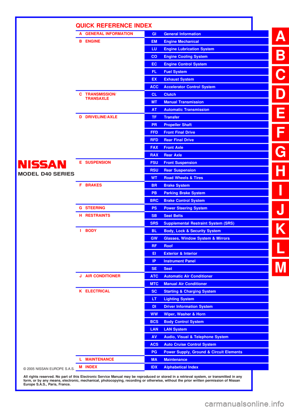
A GENERAL INFORMATION
B ENGINE
C TRANSMISSION/TRANSAXLE
D DRIVELINE/AXLE
E SUSPENSION F BRAKES
G STEERING H RESTRAINTS
I BODY
J AIR CONDITIONER
K ELECTRICAL
L MAINTENANCE
M INDEXGI General Information
EM Engine Mechanical
LU Engine Lubrication System
CO Engine Cooling System
EC Engine Control System
FL Fuel System
EX Exhaust System
ACC Accelerator Control System
CL Clutch
MTManualTransmission
AT Automatic Transmission
TF Transfer
PR Propeller Shaft
FFD Front Final Drive
RFD Rear Final Drive
FAX Front Axle
RAX Rear Axle
FSU Front Suspension
RSU Rear Suspension
WT Road Wheels & Tires
BR Brake System
PB Parking Brake System
BRC Brake Control System
PS Power Steering System
SB Seat Belts
SRS Supplemental Restraint System (SRS)
BL Body, Lock & Security System
GW Glasses, Window System & Mirrors
RF Roof
EI Exterior & Interior
IP Instrument Panel
SE Seat
ATC Automatic Air Conditioner
MTC Manual Air Conditioner
SC Starting & Charging System
LT Lighting System
DI Driver Information System
WW Wiper, Washer & Horn
BCS Body Control System
LAN LAN System
AV Audio, Visual & Telephone System
ACS Auto Cruise Control System
PG Power Supply, Ground & Circuit Elements
MA Maintenance
IDX Alphabetical Index
QUICK REFERENCE INDEX
A
B
C
D
E
F
G
H
I
J
K
L
M
Page 46 of 3171

AT-38
TROUBLE DIAGNOSIS
DIAGNOSTIC WORKSHEET
Information from Customer
KEY POINTS
lWHAT..... Vehicle & A/T model
lWHEN..... Date, Frequencies
lWHERE..... Road conditions
lHOW..... Operating conditions, Symptoms
Diagnostic Worksheet Chart
Customer name MR/MS Model & Year VIN
Trans. Model Engine Mileage
Malfunction Date Manuf. Date In Service Date
FrequencyoContinuousoIntermittent (times a day)
SymptomsoVehicle does not move. (oAny positionoParticular position)
oNo up-shift (o1st®2ndo2nd®3rdo3rd®4tho4th®5th)
oNo down-shift (o5th®4tho4th®3rdo3rd®2ndo2nd®1st)
oLock-up malfunction
oShift point too high or too low.
oShift shock or slip (oN®DoLock-upoAny drive position)
oNoise or vibration
oNo kick down
oNo pattern select
oOthers
()
OD OFF indicator lampoContinuously litoNot lit
1oRead the item on cautions concerning fail-safe and understand the customer's complaint.AT- 3 4
2oA/T fluid inspectionAT- 4 3oLeak (Repair leak location.)
oState
oAmount
3oStall test and line pressure testAT- 4 3
AT- 4 4oStall te st
oTorque converter one-way clutch
oFront brake
oHigh and low reverse clutch
oLow coast brake
oForward brake
oReverse brake
oForward one-way clutcho1st one-way clutch
o3rd one-way clutch
oEngine
oLine pressure low
oExcept for input clutch and direct
clutch, clutches and brakes OK
oLine pressure inspection - Suspected part:
Page 787 of 3171

BR-1
BRAKE SYSTEM
F BRAKES
CONTENTS
C
D
E
G
H
I
J
K
L
M
SECTIONBR
A
B
BR
BRAKE SYSTEM
PRECAUTIONS .......................................................... 3
Precautions for Supplemental Restraint System
(SRS)“AIRBAG”and“SEATBELTPRE-TEN-
SIONER” .................................................................. 3
Precautions for Brake System .................................. 3
PREPARATION ........................................................... 4
Special Service Tools ............................................... 4
Commercial Service Tools ........................................ 4
NOISE, VIBRATION AND HARSHNESS (NVH)
TROUBLESHOOTING ................................................ 5
NVH Troubleshooting Chart ..................................... 5
BRAKE PEDAL .......................................................... 6
Inspection and Adjustment ....................................... 6
ADJUSTMENT ...................................................... 7
Removal and Installation .......................................... 8
COMPONENTS .................................................... 8
REMOVAL ............................................................. 8
INSPECTION AFTER REMOVAL ......................... 9
INSTALLATION ..................................................... 9
BRAKE FLUID .......................................................... 10
On-board Inspection ............................................... 10
CHECKING BRAKE FLUID LEVEL .................... 10
Drain and Refill ....................................................... 10
Bleeding Brake System ........................................... 11
LHD MODEL ........................................................ 11
RHD MODEL ........................................................ 11
BRAKE TUBE AND HOSE ....................................... 12
Hydraulic Circuit ..................................................... 12
Removal and Installation of Front Brake Tube and
Brake Hose ............................................................ 13
REMOVAL ........................................................... 13
INSTALLATION ................................................... 13
Removal and Installation of Rear Brake Tube and
Brake Hose ............................................................ 13
REMOVAL ........................................................... 13
INSTALLATION ................................................... 13
Inspection after Installation .................................... 14
LOAD SENSING VALVE .......................................... 15
Removal and Installation ........................................ 15
REMOVAL ........................................................... 15INSTALLATION ................................................... 15
Inspection ............................................................... 16
INSPECTION ...................................................... 16
BRAKE MASTER CYLINDER .................................. 17
On-Board Inspection ............................................... 17
LEAK INSPECTION ............................................ 17
Removal and Installation ........................................ 17
REMOVAL ........................................................... 17
INSTALLATION ................................................... 17
Components ........................................................... 17
Disassembly and Assembly .................................... 18
DISASSEMBLY ................................................... 18
ASSEMBLY ......................................................... 18
BRAKE BOOSTER ................................................... 19
On-Vehicle Service ................................................. 19
OPERATING CHECK .......................................... 19
AIRTIGHT CHECK .............................................. 19
Removal and Installation ........................................ 20
COMPONENTS ................................................... 20
REMOVAL ........................................................... 20
INSPECTION AFTER REMOVAL ....................... 20
INSTALLATION ................................................... 21
VACUUM LINES ....................................................... 22
Component ............................................................. 22
Removal and Installation ........................................ 23
Inspection ............................................................... 23
VISUAL INSPECTION ......................................... 23
CHECK VALVE INSPECTION ............................. 23
FRONT DISC BRAKE ............................................... 24
On-Board Inspection ............................................... 24
PAD WEAR INSPECTION ................................... 24
Components ........................................................... 24
Removal and Installation of Brake Pad .................. 25
REMOVAL ........................................................... 25
INSTALLATION ................................................... 25
Removal and Installation of Brake Caliper Assembly
... 26
REMOVAL ........................................................... 26
INSTALLATION ................................................... 26
Disassembly and Assembly of Brake Caliper
Page 823 of 3171
BRC-1
BRAKE CONTROL SYSTEM
F BRAKES
CONTENTS
C
D
E
G
H
I
J
K
L
M
SECTIONBRC
A
B
BRC
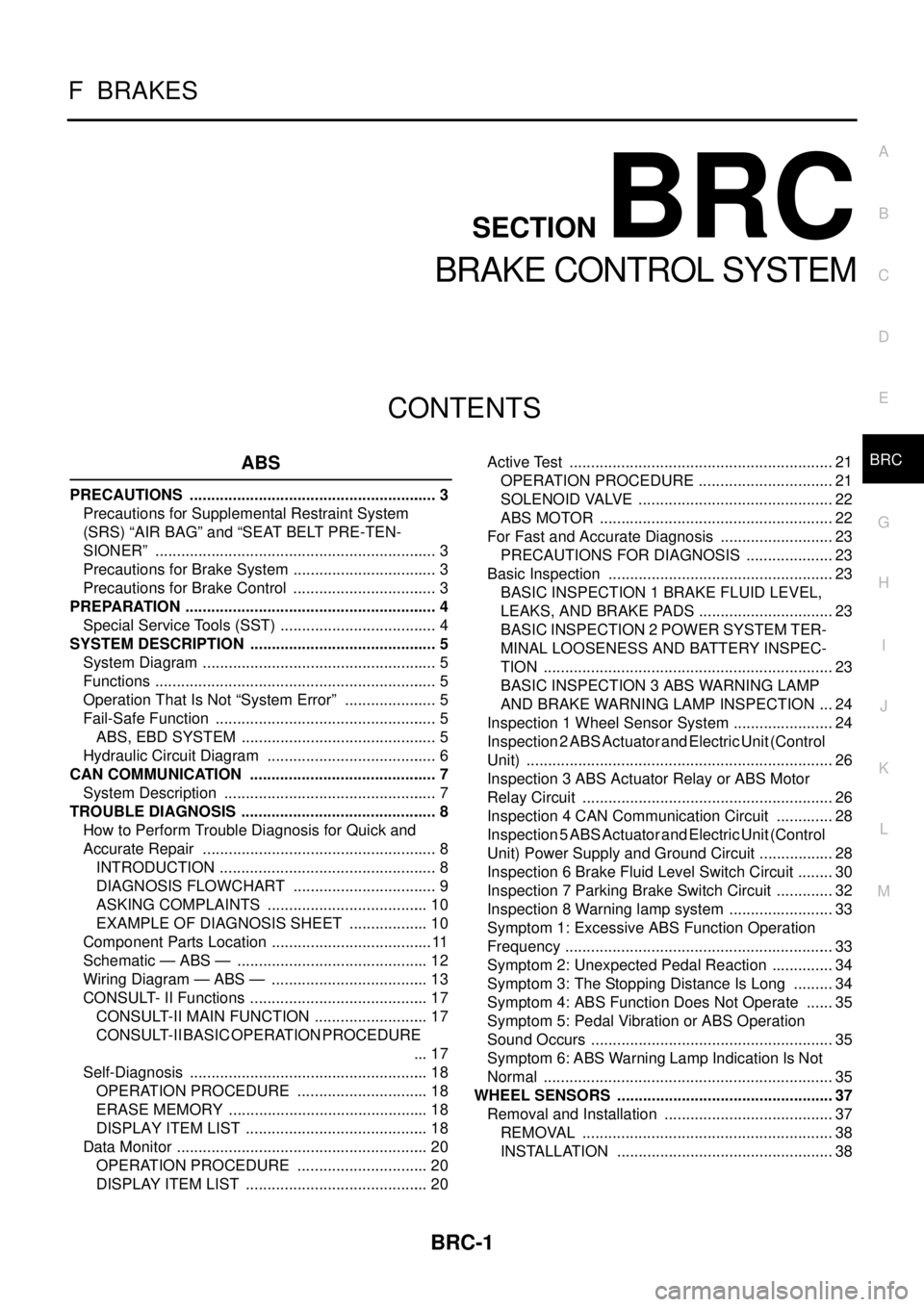
BRAKE CONTROL SYSTEM
ABS
PRECAUTIONS .......................................................... 3
Precautions for Supplemental Restraint System
(SRS)“AIRBAG”and“SEATBELTPRE-TEN-
SIONER” .................................................................. 3
Precautions for Brake System .................................. 3
Precautions for Brake Control .................................. 3
PREPARATION ........................................................... 4
Special Service Tools (SST) ..................................... 4
SYSTEM DESCRIPTION ............................................ 5
System Diagram ....................................................... 5
Functions .................................................................. 5
Operation That Is Not “System Error” ...................... 5
Fail-Safe Function .................................................... 5
ABS, EBD SYSTEM .............................................. 5
Hydraulic Circuit Diagram ........................................ 6
CAN COMMUNICATION ............................................ 7
System Description .................................................. 7
TROUBLE DIAGNOSIS .............................................. 8
How to Perform Trouble Diagnosis for Quick and
Accurate Repair ....................................................... 8
INTRODUCTION ................................................... 8
DIAGNOSIS FLOWCHART .................................. 9
ASKING COMPLAINTS ...................................... 10
EXAMPLE OF DIAGNOSIS SHEET ................... 10
Component Parts Location ...................................... 11
Schematic — ABS — ............................................. 12
Wiring Diagram — ABS — ..................................... 13
CONSULT- II Functions .......................................... 17
CONSULT-II MAIN FUNCTION ........................... 17
CONSULT-II BASIC OPERATION PROCEDURE
... 17
Self-Diagnosis ........................................................ 18
OPERATION PROCEDURE ............................... 18
ERASE MEMORY ............................................... 18
DISPLAY ITEM LIST ........................................... 18
Data Monitor ........................................................... 20
OPERATION PROCEDURE ............................... 20
DISPLAY ITEM LIST ........................................... 20Active Test .............................................................. 21
OPERATION PROCEDURE ................................ 21
SOLENOID VALVE .............................................. 22
ABS MOTOR ....................................................... 22
For Fast and Accurate Diagnosis ........................... 23
PRECAUTIONS FOR DIAGNOSIS ..................... 23
Basic Inspection ..................................................... 23
BASIC INSPECTION 1 BRAKE FLUID LEVEL,
LEAKS, AND BRAKE PADS ................................ 23
BASIC INSPECTION 2 POWER SYSTEM TER-
MINAL LOOSENESS AND BATTERY INSPEC-
TION .................................................................... 23
BASIC INSPECTION 3 ABS WARNING LAMP
AND BRAKE WARNING LAMP INSPECTION .... 24
Inspection 1 Wheel Sensor System ........................ 24
Inspection 2 ABS Actuator and Electric Unit (Control
Unit) ........................................................................ 26
Inspection 3 ABS Actuator Relay or ABS Motor
Relay Circuit ........................................................... 26
Inspection 4 CAN Communication Circuit .............. 28
Inspection 5 ABS Actuator and Electric Unit (Control
Unit) Power Supply and Ground Circuit .................. 28
Inspection 6 Brake Fluid Level Switch Circuit ......... 30
Inspection 7 Parking Brake Switch Circuit .............. 32
Inspection 8 Warning lamp system ......................... 33
Symptom 1: Excessive ABS Function Operation
Frequency ............................................................... 33
Symptom 2: Unexpected Pedal Reaction ............... 34
Symptom 3: The Stopping Distance Is Long .......... 34
Symptom 4: ABS Function Does Not Operate ....... 35
Symptom 5: Pedal Vibration or ABS Operation
Sound Occurs ......................................................... 35
Symptom 6: ABS Warning Lamp Indication Is Not
Normal .................................................................... 35
WHEEL SENSORS ................................................... 37
Removal and Installation ........................................ 37
REMOVAL ........................................................... 38
INSTALLATION ................................................... 38
Page 889 of 3171

OVERHEATING CAUSE ANALYSIS
CO-5
C
D
E
F
G
H
I
J
K
L
MA
CO
Except cool-
ing system
parts mal-
function— Overload on engineAbusive drivingHigh engine rpm under no
load
Driving in low gear for
extended time
Driving at extremely high
speed
Powertrain system mal-
function
— Installed improper size
wheels and tires
Dragging brakes
Improper ignition timing
Blocked or restricted air
flowBlocked bumper —
— Blocked radiator grilleInstalled car brassiere
Mud contamination or
paper clogging
Blocked radiator —
Blocked condenser
Blocked air flow
Installed large fog lamp Symptom Check items
Page 1536 of 3171
FAX-4
NOISE, VIBRATION, AND HARSHNESS (NVH) TROUBLESHOOTING
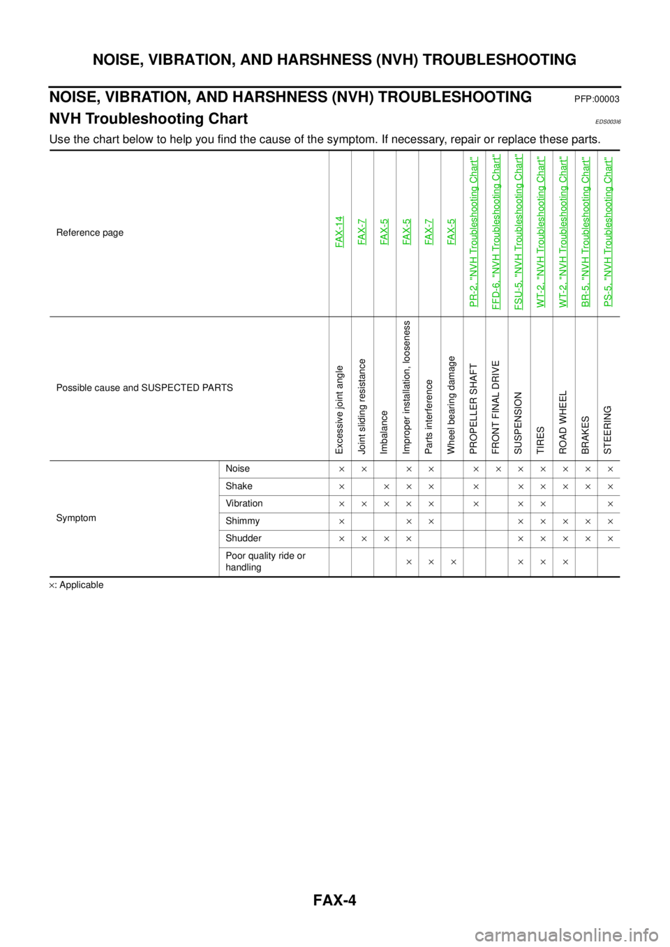
NOISE, VIBRATION, AND HARSHNESS (NVH) TROUBLESHOOTING
PFP:00003
NVH Troubleshooting ChartEDS003I6
Use the chart below to help you find the cause of the symptom. If necessary, repair or replace these parts.
´: ApplicableReference page
FAX-14FAX-7FAX-5FAX-5FAX-7FAX-5
PR-2, "
NVH Troubleshooting Chart
"
FFD-6, "
NVH Troubleshooting Chart
"
FSU-5, "
NVH Troubleshooting Chart
"
WT-2, "
NVH Troubleshooting Chart
"
WT-2, "
NVH Troubleshooting Chart
"
BR-5, "
NVH Troubleshooting Chart
"
PS-5, "
NVH Troubleshooting Chart
"
Possible cause and SUSPECTED PARTS
Excessive joint angle
Joint sliding resistance
Imbalance
Improper installation, looseness
Parts interference
Wheel bearing damage
PROPELLER SHAFT
FRONT FINAL DRIVE
SUSPENSION
TIRES
ROAD WHEEL
BRAKES
STEERING
SymptomNoise´´ ´´ ´´´´´´´
Shake´ ´´´ ´ ´´´´´
Vibration´´´´´ ´ ´´ ´
Shimmy´ ´´ ´´´´´
Shudder´´´´ ´´´´´
Poor quality ride or
handling´´´ ´´´
Page 1552 of 3171
FFD-6
NOISE, VIBRATION AND HARSHNESS (NVH) TROUBLESHOOTING
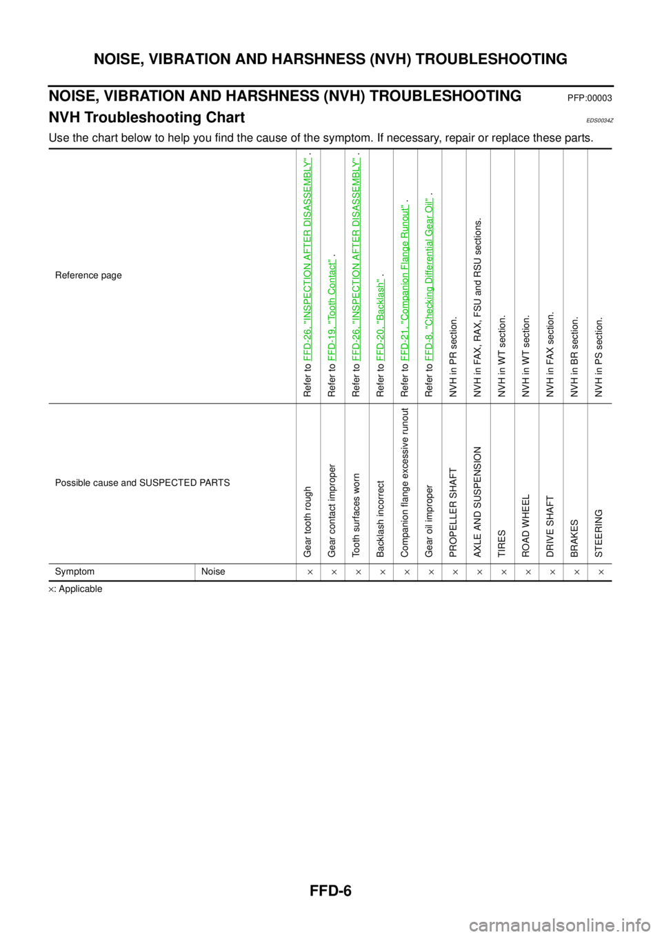
NOISE, VIBRATION AND HARSHNESS (NVH) TROUBLESHOOTING
PFP:00003
NVH Troubleshooting ChartEDS0034Z
Use the chart below to help you find the cause of the symptom. If necessary, repair or replace these parts.
´: ApplicableReference page
Refer toFFD-26, "
INSPECTION AFTER DISASSEMBLY
".
Refer toFFD-19, "
To o t h C o n t a c t
".
Refer toFFD-26, "
INSPECTION AFTER DISASSEMBLY
".
Refer toFFD-20, "
Backlash
".
Refer toFFD-21, "
Companion Flange Runout
".
Refer toFFD-8, "
Checking Differential Gear Oil
".
NVH in PR section.
NVH in FAX, RAX, FSU and RSU sections.
NVH in WT section.
NVH in WT section.
NVH in FAX section.
NVH in BR section.
NVH in PS section.
Possible cause and SUSPECTED PARTS
Gear tooth rough
Gear contact improper
Tooth surfaces worn
Backlash incorrect
Companion flange excessive runout
Gear oil improper
PROPELLER SHAFT
AXLE AND SUSPENSION
TIRES
ROAD WHEEL
DRIVE SHAFT
BRAKES
STEERING
Symptom Noise´´´´´´´´´´´´´
Page 1605 of 3171
NOISE, VIBRATION, AND HARSHNESS (NVH) TROUBLESHOOTING
FSU-5
C
D
F
G
H
I
J
K
L
MA
B
FSU
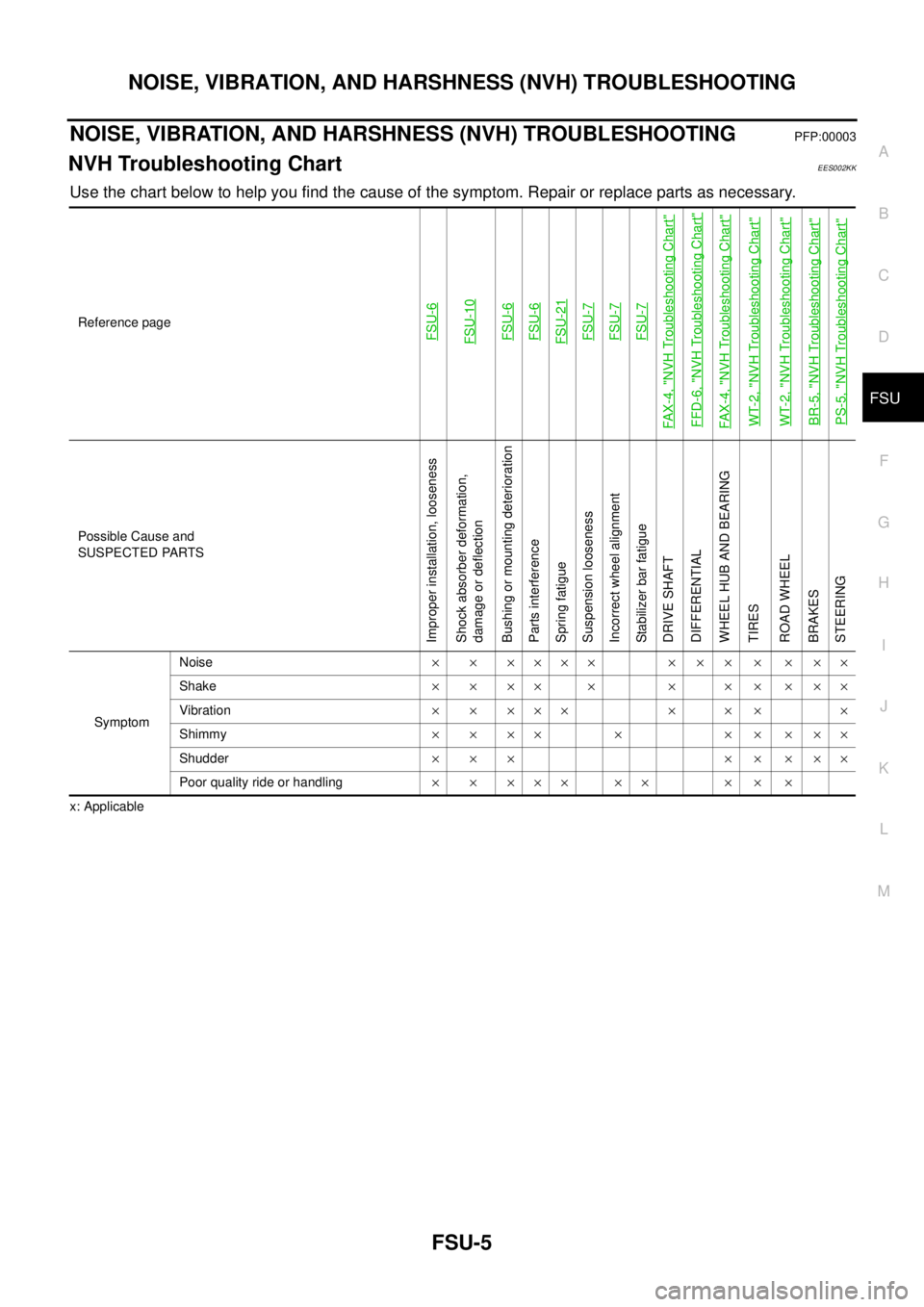
NOISE, VIBRATION, AND HARSHNESS (NVH) TROUBLESHOOTINGPFP:00003
NVH Troubleshooting ChartEES002KK
Use the chart below to help you find the cause of the symptom. Repair or replace parts as necessary.
x: ApplicableReference page
FSU-6FSU-10FSU-6FSU-6FSU-21FSU-7FSU-7FSU-7
FAX-4, "
NVH Troubleshooting Chart
"
FFD-6, "
NVH Troubleshooting Chart
"
FAX-4, "
NVH Troubleshooting Chart
"
WT-2, "
NVH Troubleshooting Chart
"
WT-2, "
NVH Troubleshooting Chart
"
BR-5, "
NVH Troubleshooting Chart
"
PS-5, "
NVH Troubleshooting Chart
"
Possible Cause and
SUSPECTED PARTS
Improper installation, looseness
Shock absorber deformation,
damage or deflection
Bushing or mounting deterioration
Parts interference
Spring fatigue
Suspension looseness
Incorrect wheel alignment
Stabilizer bar fatigue
DRIVE SHAFT
DIFFERENTIAL
WHEEL HUB AND BEARING
TIRES
ROAD WHEEL
BRAKES
STEERING
SymptomNoise´ ´ ´´´´ ´ ´ ´ ´ ´ ´´
Shake´´´´ ´ ´ ´´´´´
Vibration´ ´ ´´´ ´ ´ ´ ´
Shimmy´´´´ ´ ´´´´´
Shudder´´´ ´´´´´
Poor quality ride or handling´ ´ ´´´ ´´ ´ ´ ´