2005 NISSAN NAVARA bulb
[x] Cancel search: bulbPage 923 of 3171
COMBINATION METERS
DI-13
C
D
E
F
G
H
I
J
L
MA
B
DI
Self-Diagnosis Mode of Combination MeterEKS00L8K
FUNCTION
The following items can be checked during self-diagnosis mode.
lSweep of gauges pointer
lPresent gauge data values
lOdo/trip meter display and clock display segments
lCondition of warning lamps/indicator lamps controlled by unified meter control unit
lBattery voltage
lDriver's seat belt buckle switch status
lCPU of unified meter control unit status
OPERATION PROCEDURE
To initiate combination meter self-diagnosis mode, refer to the following procedure.
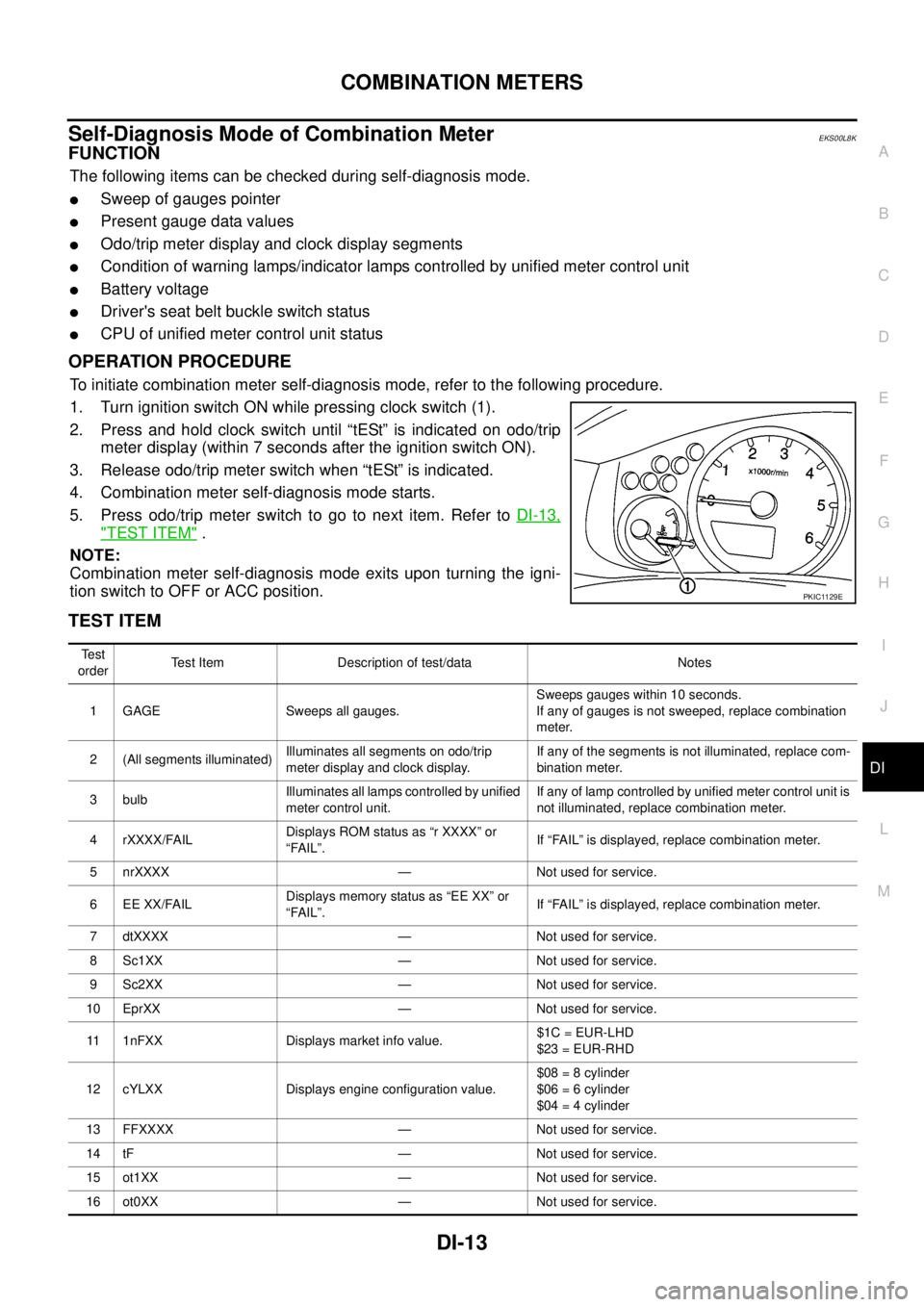
1. Turn ignition switch ON while pressing clock switch (1).
2. Press and hold clock switch until “tESt” is indicated on odo/trip
meter display (within 7 seconds after the ignition switch ON).
3. Release odo/trip meter switch when “tESt” is indicated.
4. Combination meter self-diagnosis mode starts.
5. Pressodo/tripmeterswitchtogotonextitem.RefertoDI-13,
"TEST ITEM".
NOTE:
Combination meter self-diagnosis mode exits upon turning the igni-
tion switch to OFF or ACC position.
TEST ITEM
PKIC1129E
Te s t
orderTest Item Description of test/data Notes
1 GAGE Sweeps all gauges.Sweeps gauges within 10 seconds.
If any of gauges is not sweeped, replace combination
meter.
2 (All segments illuminated)Illuminates all segments on odo/trip
meter display and clock display.If any of the segments is not illuminated, replace com-
bination meter.
3 bulbIlluminates all lamps controlled by unified
meter control unit.If any of lamp controlled by unified meter control unit is
not illuminated, replace combination meter.
4 rXXXX/FAILDisplays ROM status as “r XXXX” or
“FAIL”.If “FAIL” is displayed, replace combination meter.
5 nrXXXX — Not used for service.
6 EE XX/FAILDisplays memory status as “EE XX” or
“FAIL”.If “FAIL” is displayed, replace combination meter.
7 dtXXXX — Not used for service.
8 Sc1XX — Not used for service.
9 Sc2XX — Not used for service.
10 EprXX — Not used for service.
11 1nFXX Displays market info value.$1C = EUR-LHD
$23 = EUR-RHD
12 cYLXX Displays engine configuration value.$08 = 8 cylinder
$06 = 6 cylinder
$04 = 4 cylinder
13 FFXXXX — Not used for service.
14 tF — Not used for service.
15 ot1XX — Not used for service.
16 ot0XX — Not used for service.
Page 1008 of 3171
EC-28
ON BOARD DIAGNOSTIC (OBD) SYSTEM
lIf the battery is disconnected, the emission-related diagnostic information will be lost within 24
hours.
lThe following data are cleared when the ECM memory is erased.
–Diagnostic trouble codes
–Freeze frame data
–Fuel pump learning value
Actual work procedures are explained using a DTC as an example. Be careful so that not only the DTC, but all
of the data listed above, are cleared from the ECM memory during work procedures.
Freeze Frame DataEBS01KCP
The ECM records the driving conditions such as calculated load value, engine coolant temperature, engine
speed, vehicle speed and intake manifold pressure at the moment a malfunction is detected.
The data, stored together with the DTC data, are called freeze frame data and displayed on CONSULT-II. For
details, seeEC-28, "
Freeze Frame Data".
Only one set of freeze frame data can be stored in the ECM. If freeze frame data is stored in the ECM memory
and another freeze frame data occurs later, the first (original) freeze frame data remains unchanged in the
ECM memory.
Freeze frame data (along with the DTCs) are cleared when the ECM memory is erased. Procedures for clear-
ing the ECM memory are described inEC-27, "
HOW TO ERASE DTC".
NATS (Nissan Anti-theft System)EBS01KCQ
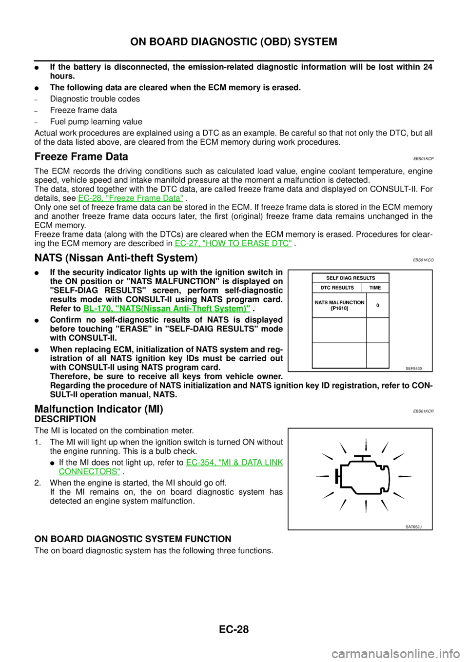
lIf the security indicator lights up with the ignition switch in
the ON position or "NATS MALFUNCTION" is displayed on
"SELF-DIAG RESULTS" screen, perform self-diagnostic
results mode with CONSULT-II using NATS program card.
Refer toBL-170, "
NATS(Nissan Anti-Theft System)".
lConfirm no self-diagnostic results of NATS is displayed
before touching "ERASE" in "SELF-DAIG RESULTS" mode
with CONSULT-II.
lWhen replacing ECM, initialization of NATS system and reg-
istration of all NATS ignition key IDs must be carried out
with CONSULT-II using NATS program card.
Therefore, be sure to receive all keys from vehicle owner.
Regarding the procedure of NATS initialization and NATS ignition key ID registration, refer to CON-
SULT-II operation manual, NATS.
Malfunction Indicator (MI)EBS01KCR
DESCRIPTION
The MI is located on the combination meter.
1. The MI will light up when the ignition switch is turned ON without
the engine running. This is a bulb check.
lIf the MI does not light up, refer toEC-354, "MI&DATA LINK
CONNECTORS".
2. When the engine is started, the MI should go off.
If the MI remains on, the on board diagnostic system has
detected an engine system malfunction.
ON BOARD DIAGNOSTIC SYSTEM FUNCTION
The on board diagnostic system has the following three functions.
SEF543X
SAT652J
Page 1009 of 3171
ON BOARD DIAGNOSTIC (OBD) SYSTEM
EC-29
C
D
E
F
G
H
I
J
K
L
MA
EC
HOWTOSWITCHDIAGNOSTICTESTMODE
NOTE:
lIt is better to count the time accurately with a clock.
lIt is impossible to switch the diagnostic mode when an accelerator pedal position sensor circuit
has a malfunction.
lAlways ECM returns to Diagnostic Test Mode I after ignition switch is turned OFF.
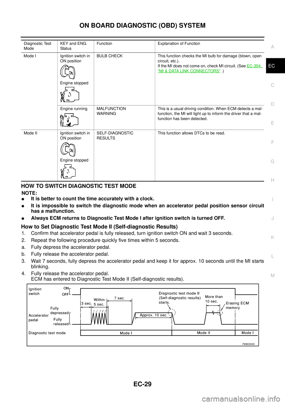
How to Set Diagnostic Test Mode II (Self-diagnostic Results)
1. Confirm that accelerator pedal is fully released, turn ignition switch ON and wait 3 seconds.
2. Repeat the following procedure quickly five times within 5 seconds.
a. Fully depress the accelerator pedal.
b. Fully release the accelerator pedal.
3. Wait 7 seconds, fully depress the accelerator pedal and keep it for approx. 10 seconds until the MI starts
blinking.
4. Fully release the accelerator pedal.
ECM has entered to Diagnostic Test Mode II (Self-diagnostic results).
Diagnostic Test
ModeKEY and ENG.
Statu sFunction Explanation of Function
Mode I Ignition switch in
ON position
Engine stoppedBULB CHECK This function checks the MI bulb for damage (blown, open
circuit, etc.).
If the MI does not come on, check MI circuit. (SeeEC-354,
"MI&DATA LINK CONNECTORS".)
Engine running MALFUNCTION
WARNINGThis is a usual driving condition. When ECM detects a mal-
function, the MI will light up to inform the driver that a mal-
function has been detected.
Mode II Ignition switch in
ON position
Engine stoppedSELF-DIAGNOSTIC
RESULTSThis function allows DTCs to be read.
PBIB0092E
Page 1010 of 3171
EC-30
ON BOARD DIAGNOSTIC (OBD) SYSTEM
How to Erase Diagnostic Test Mode II (Self-diagnostic Results)
1. Set ECM in Diagnostic Test Mode II (Self-diagnostic results). Refer toEC-29, "How to Set Diagnostic Test
Mode II (Self-diagnostic Results)".
2. Fully depress the accelerator pedal and keep it for more than 10 seconds.
The emission-related diagnostic information has been erased from the backup memory in the ECM.
3. Fully release the accelerator pedal, and confirm the DTC 0000 is displayed.
DIAGNOSTIC TEST MODE I — BULB CHECK
In this mode, the MI on the combination meter should stay ON. If it remains OFF, check the bulb. Refer toEC-
354, "MI&DATA LINK CONNECTORS".
DIAGNOSTIC TEST MODE I — MALFUNCTION WARNING
These DTC numbers are clarified in Diagnostic Test Mode II (SELF-DIAGNOSTIC RESULTS)
DIAGNOSTIC TEST MODE II — SELF-DIAGNOSTIC RESULTS
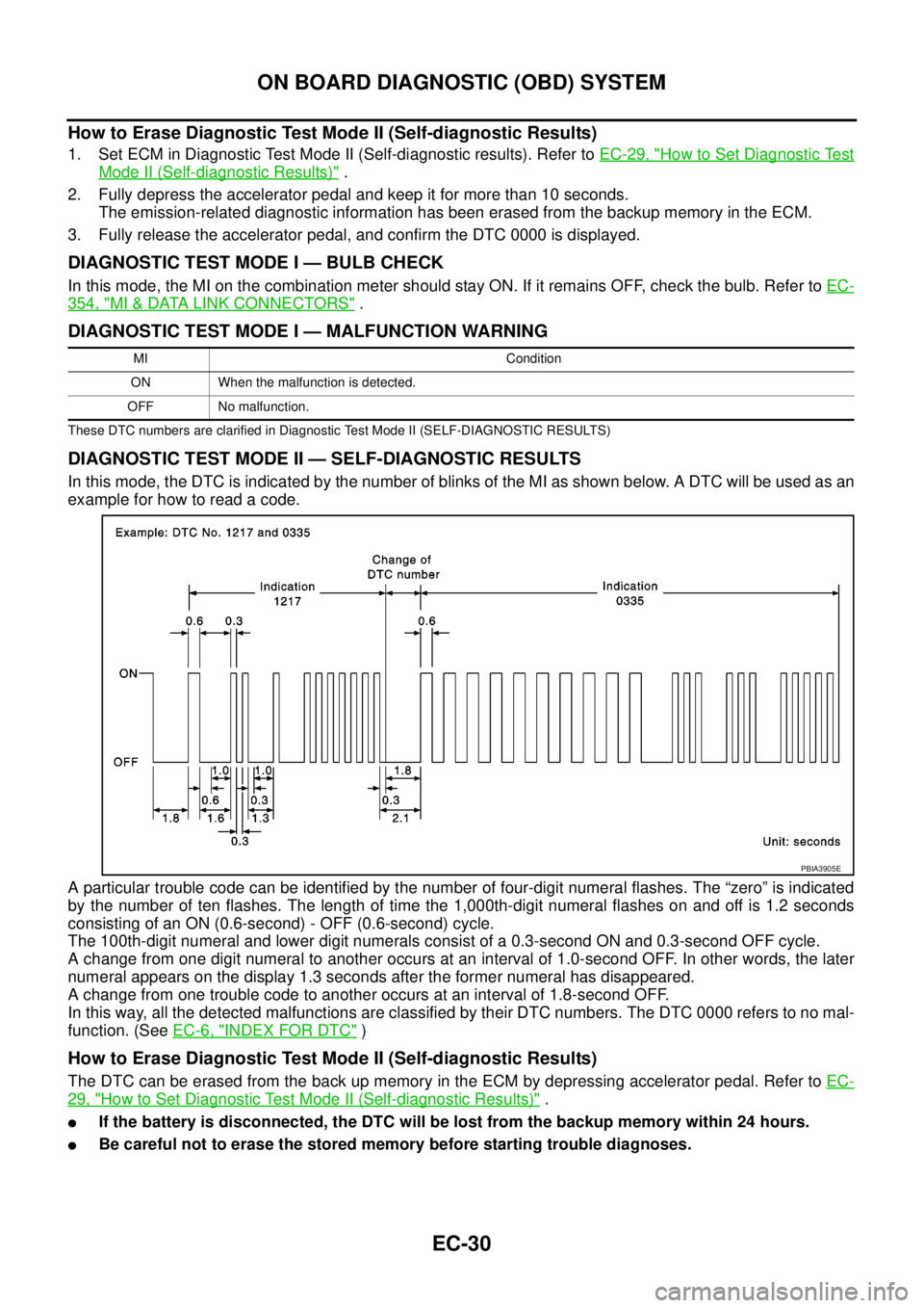
In this mode, the DTC is indicated by the number of blinks of the MI as shown below. A DTC will be used as an
example for how to read a code.
A particular trouble code can be identified by the number of four-digit numeral flashes. The “zero” is indicated
by the number of ten flashes. The length of time the 1,000th-digit numeral flashes on and off is 1.2 seconds
consisting of an ON (0.6-second) - OFF (0.6-second) cycle.
The 100th-digit numeral and lower digit numerals consist of a 0.3-second ON and 0.3-second OFF cycle.
A change from one digit numeral to another occurs at an interval of 1.0-second OFF. In other words, the later
numeral appears on the display 1.3 seconds after the former numeral has disappeared.
A change from one trouble code to another occurs at an interval of 1.8-second OFF.
In this way, all the detected malfunctions are classified by their DTC numbers. The DTC 0000 refers to no mal-
function. (SeeEC-6, "
INDEX FOR DTC")
How to Erase Diagnostic Test Mode II (Self-diagnostic Results)
The DTC can be erased from the back up memory in the ECM by depressing accelerator pedal. Refer toEC-
29, "How to Set Diagnostic Test Mode II (Self-diagnostic Results)".
lIf the battery is disconnected, the DTC will be lost from the backup memory within 24 hours.
lBe careful not to erase the stored memory before starting trouble diagnoses.
MI Condition
ON When the malfunction is detected.
OFF No malfunction.
PBIA3905E
Page 1652 of 3171
GI-30
SERVICE INFORMATION FOR ELECTRICAL INCIDENT
If repairs are needed always use wire that is of the same or larger gauge.
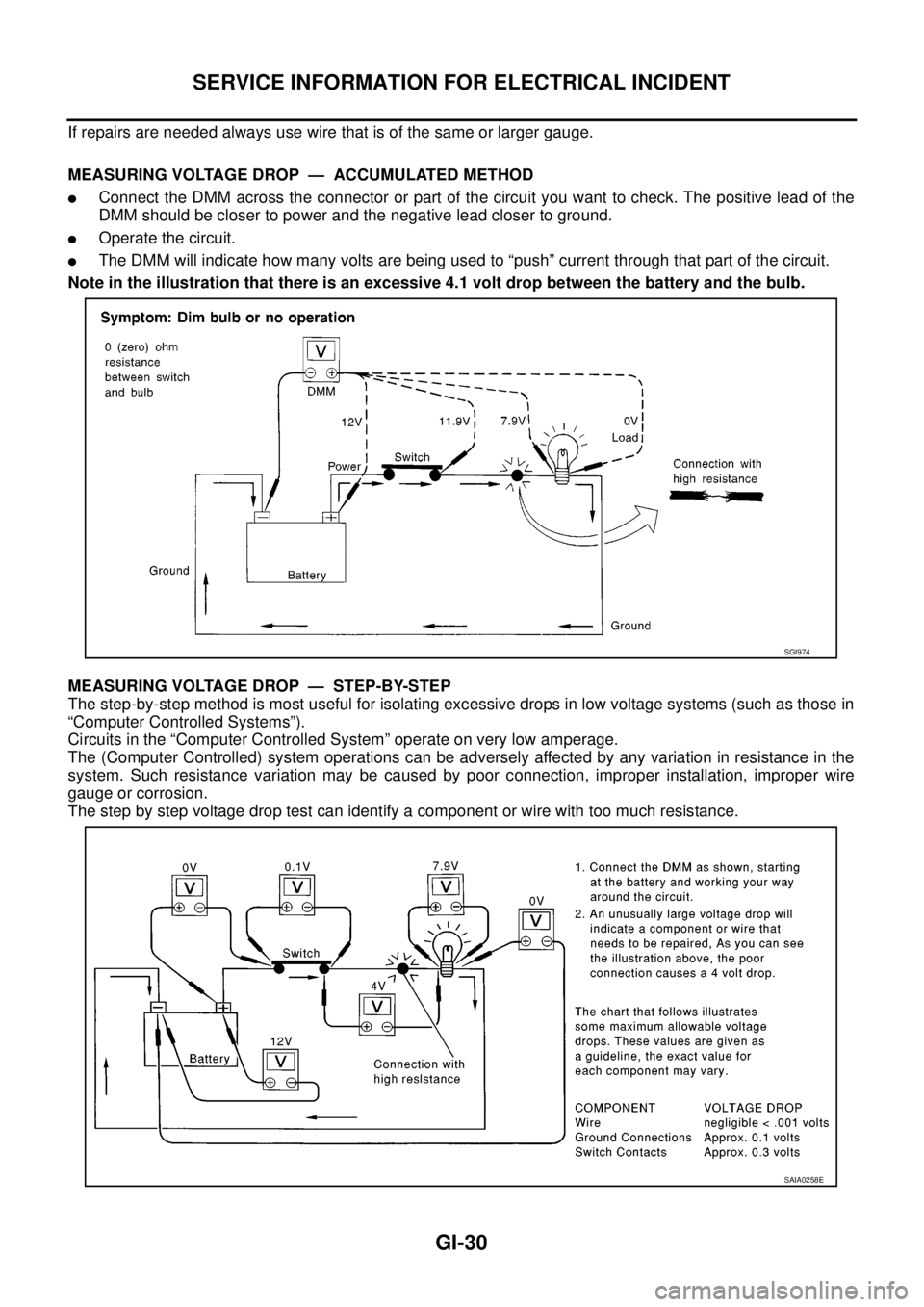
MEASURING VOLTAGE DROP — ACCUMULATED METHOD
lConnect the DMM across the connector or part of the circuit you want to check. The positive lead of the
DMM should be closer to power and the negative lead closer to ground.
lOperate the circuit.
lThe DMM will indicate how many volts are being used to “push” current through that part of the circuit.
Note in the illustration that there is an excessive 4.1 volt drop between the battery and the bulb.
MEASURING VOLTAGE DROP — STEP-BY-STEP
The step-by-step method is most useful for isolating excessive drops in low voltage systems (such as those in
“Computer Controlled Systems”).
Circuits in the “Computer Controlled System” operate on very low amperage.
The (Computer Controlled) system operations can be adversely affected by any variation in resistance in the
system. Such resistance variation may be caused by poor connection, improper installation, improper wire
gauge or corrosion.
The step by step voltage drop test can identify a component or wire with too much resistance.
SGI974
SAIA0258E
Page 1754 of 3171
IDX-2
ALPHABETICAL INDEX
Numerics
4LO indicator lamp .............................................TF-16
4LO switch ..............................................TF-56,TF-59
4WD - Wiring diagram .......................................TF-25
4WD shift indicator lamp ....................................TF-16
4WD shift switch .........................TF-16,TF-59,TF-62
4WD system description ....................................TF-15
4WD system diagram ........................................TF-18
4WD warning lamp ............................................TF-17
A
A/C air flow .......................................ATC-30
,MTC-30
A/C compressor clutch removal and installation ...........
ATC-143
,MTC-123
A/C compressor mounting ............ATC-142,MTC-122
A/C compressor precaution ..............ATC-12,MTC-12
A/C compressor special service tool .ATC-16,MTC-16
A/C control operation (auto A/C) .......ATC-28,MTC-28
A/C diagnostic work flow (auto A/C)ATC-103,MTC-95
A/C evaporator ..............................ATC-149,MTC-129
A/C HFC134a (R134a) system precaution .......ATC-4,
MTC-4
A/C HFC134a (R134a) system service procedure .......
ATC-138
,MTC-118
A/C HFC134a (R134a) system service tools ..ATC-16,
MTC-16
A/C HFC134a system service equipment precaution ...
ATC-12
,MTC-12
A/C lubricant (R134a) .......................ATC-24,MTC-24
A/C lubrication oil ..............................ATC-24,MTC-24
A/C operational check .......................ATC-57,MTC-53
A/C self-diagnoses (auto A/C) .......ATC-55,ATC-103,
MTC-51
,MTC-95
A/C service data specification .......ATC-154,MTC-135
A/C trouble diagnoses (auto A/C) .....ATC-33,MTC-33
A/C, A - Wiring diagram ....................ATC-39,MTC-39
A/T fluid checking ......................AT-12,AT-43,MA-29
A/T fluid replacement .............................AT-11,MA-31
A/T fluid temperature sensor ...........................AT-118
A/T IND - Wiring diagram ....................................DI-49
A/T indicator ........................................................DI-48
A/T self-diagnoses .............................................AT-89
A/T shift lock system ........................................AT-212
A/T trouble diagnoses ........................................AT-34
A/T Wiring diagram AT - CAN ............................AT-92
A/T Wiring diagram AT - FTS ..........................AT-119
A/T Wiring diagram AT - MAIN ........................AT-164
A/T Wiring diagram AT - NONDTC ..................AT-174
A/T Wiring diagram AT - PNP/SW ...................AT-100
A/T Wiring diagram AT - STSIG ........................AT-95
A/T Wiring diagram AT - VSS A/T ...................AT-105
ABS - Wiring diagram .....................................BRC-13
Accelerator control system ...............................ACC-2
Accelerator pedal position (APP) sensor ........EC-108,
EC-142
,EC-275
Aiming adjustment ..................................LT-28,LT-85
Air bag ..............................................................SRS-3
Air bag disposal ..............................................SRS-49
Air bleeding (hydraulic clutch) ..............................CL-8
Air cleaner and air duct .....................................EM-15
Air cleaner filter .................................................EM-17
Air cleaner filter replacement ............................MA-25
Air conditioner cut control ..................................EC-20
Air flow meter - See Mass air flow sensor ..........EC-92
Air mix. door motor .........................................ATC-68
Alternator ...........................................................SC-14
Ambient sensor .............................ATC-105,ATC-117
Angular tightening application .............................EM-4
APP2PW - Wiring diagram ..............................EC-229
APPS - Wiring diagram ....................................EC-110
APPS2 - Wiring diagram ..................................EC-144
APPS3 - Wiring diagram ..................................EC-277
ASC/BS - Wiring diagram ................................EC-192
ASC/SW - Wiring diagram ...............................EC-208
ASCBOF - Wiring diagram ...............................EC-331
ASCD ...............................................................EC-355
ASCD (automatic speed control device) ...........ACS-2
ASCD brake switch ...........................EC-189,EC-330
ASCD clutch switch ..........................EC-189,EC-330
ASCD indicator lamp .......................................EC-351
ASCD steering switch ......................................EC-206
ASCIND - Wiring diagram ................................EC-352
ATP switch ..............................................TF-82,TF-85
Auto air conditioner - Wiring diagramATC-39,MTC-39
Auto anti-dazzling inside mirror .......................GW-45
Autolamp ............................................................LT-49
Automatic amplifier ..........................ATC-60,MTC-55
Automatic transmission number ..............GI-58,GI-59
B
Back door trim .....................................................EI-30
BACK/L - Wiring diagram .................................LT-123
Back-up lamp ...................................................LT-123
Back-up lamp switch (M/T) ...................MT-12,MT-19
Ball joint (front) ................................................FSU-15
Barometric pressure (BARO) sensor ...............EC-293
Basic inspection .................................................EC-38
Battery .................................................................SC-5
Baulk ring (M/T) ................................................MT-21
BCM (Body control module) ..............................BCS-3
Blower motor ...ATC-80,ATC-121,MTC-71,MTC-100
Body mounting ....................................BL-189,BL-190
BOOST - Wiring diagram .................................EC-155
Brake booster ....................................................BR-19
Brake fluid level ................................................MA-35
Brake inspection ...............................................MA-35
Brake lines and cables inspection ....................MA-35
Brake master cylinder ........................................BR-17
Brake pedal ..........................................................BR-6
Brake switch ....................................................EC-330
Bulb specifications ...........................................LT-173
Bumper, front ......................................................EI-15
Bumper, rear .......................................................EI-17
Page 2084 of 3171

LT-1
LIGHTING SYSTEM
K ELECTRICAL
CONTENTS
C
D
E
F
G
H
I
J
L
M
SECTIONLT
A
B
LT
LIGHTING SYSTEM
PRECAUTIONS .......................................................... 4
Precautions for Supplemental Restraint System
(SRS)“AIRBAG”and“SEATBELTPRE-TEN-
SIONER” .................................................................. 4
General Precautions for Service Operations ............ 4
Wiring Diagrams and Trouble Diagnosis .................. 4
HEADLAMP -CONVENTIONAL TYPE- ..................... 5
Component Parts and Harness Connector Location..... 5
System Description .................................................. 5
OUTLINE ............................................................... 5
FRIENDLY LIGHTING FUNCTION ....................... 6
CAN Communication System Description ................ 6
Schematic ................................................................ 7
Wiring Diagram - H/LAMP - ...................................... 8
Terminals and Reference Value for BCM ............... 12
Terminals and Reference Values for IPDM E/R ..... 12
How to Proceed With Trouble Diagnosis ................ 13
Preliminary Check .................................................. 13
CHECK POWER SUPPLY AND GROUND CIR-
CUIT .................................................................... 13
CONSULT-II Functions (BCM) ............................... 15
CONSULT-II BASIC OPERATION ....................... 15
WORK SUPPORT ............................................... 16
DATA MONITOR ................................................. 16
ACTIVE TEST ..................................................... 17
CONSULT-II Functions (IPDM E/R) ....................... 18
CONSULT-II BASIC OPERATION ....................... 18
DATA MONITOR ................................................. 19
ACTIVE TEST ..................................................... 19
Headlamp High Beam Does Not Illuminate (Both
Sides) ..................................................................... 20
Headlamp HI Beam Does Not Illuminate (One Side)... 22
High Beam Indicator Lamp Does Not Illuminate .... 23
Headlamp LO Beam Does Not Illuminate (Both
Sides) ..................................................................... 23
Headlamp LO Beam Does Not Illuminate (One Side)
... 25
Headlamps Do Not Turn OFF ................................ 26
Aiming Adjustment ................................................. 28
LOW BEAM AND HIGH BEAM ........................... 28Bulb Replacement .................................................. 29
HEADLAMP HIGH/LOW BEAM .......................... 29
FRONT TURN SIGNAL LAMP ............................ 29
CLEARANCE LAMP ............................................ 29
Removal and Installation ........................................ 30
REMOVAL ........................................................... 30
INSTALLATION ................................................... 30
Disassembly and Assembly .................................... 30
DISASSEMBLY ................................................... 30
HEADLAMP - DAYTIME LIGHT SYSTEM - ............. 31
Component Parts and Harness Connector Location... 31
System Description ................................................. 31
OUTLINE ............................................................. 32
DAYTIME LIGHT OPERATION ........................... 32
COMBINATION SWITCH READING FUNCTION... 33
AUTO LIGHT OPERATION ................................. 33
CAN Communication System Description .............. 33
CAN Communication Unit ....................................... 33
Schematic ............................................................... 34
Wiring Diagram — DTRL — ................................... 35
Terminals and Reference Values for BCM .............. 39
Terminals and Reference Values for IPDM E/R ...... 39
How to Proceed With Trouble Diagnosis ................ 40
Preliminary Check .................................................. 40
CHECK POWER SUPPLY AND GROUND CIR-
CUIT .................................................................... 40
CONSULT-II Functions (BCM) ................................ 42
CONSULT-II BASIC OPERATION ....................... 42
DATA MONITOR ................................................. 43
ACTIVE TEST ..................................................... 44
CONSULT-II Functions (IPDM E/R) ........................ 45
CONSULT-II BASIC OPERATION ....................... 45
DATA MONITOR ................................................. 46
ACTIVE TEST ..................................................... 46
Daytime Light Control Does Not Operate Properly
(Normal Headlamps Operate Properly) .................. 47
Aiming Adjustment .................................................. 48
Bulb Replacement .................................................. 48
Removal and Installation ........................................ 48
Disassembly and Assembly .................................... 48
Page 2085 of 3171

LT-2
AUTO LIGHT SYSTEM ............................................. 49
Component Parts and Harness Connector Location... 49
System Description ................................................. 49
OUTLINE ............................................................. 49
COMBINATION SWITCH READING FUNCTION... 50
CAN Communication System Description .............. 50
Major Components and Functions .......................... 50
Schematic ............................................................... 51
Wiring Diagram — AUTO/L — ................................ 52
Terminals and Reference Values for BCM .............. 56
Terminals and Reference Values for IPDM E/R ...... 57
How to Proceed With Trouble Diagnosis ................ 57
Preliminary Check .................................................. 58
SETTING CHANGE FUNCTIONS ....................... 58
CHECK POWER SUPPLY AND GROUND CIR-
CUIT .................................................................... 58
CONSULT-II Function (BCM) .................................. 59
CONSULT-II OPERATION ................................... 59
WORK SUPPORT ............................................... 60
DATA MONITOR .................................................. 60
ACTIVE TEST ..................................................... 61
Trouble Diagnosis Chart by Symptom .................... 62
Lighting Switch Inspection ...................................... 62
Light and Rain Sensor System Inspection .............. 63
Removal and Installation of Light and Rain Sensor... 65
REMOVAL ........................................................... 65
INSTALLATION .................................................... 65
HEADLAMP AIMING CONTROL (MANUAL) ........... 66
Schematic ............................................................... 66
Wiring Diagram — H/AIM — ................................... 67
Removal and Installation ........................................ 70
Switch Circuit Inspection ........................................ 70
FRONT FOG LAMP .................................................. 71
Component Parts and Harness Connector Location... 71
System Description ................................................. 71
OUTLINE ............................................................. 71
COMBINATION SWITCH READING FUNCTION... 72
CAN Communication System Description .............. 72
Schematic ............................................................... 73
Wiring Diagram — F/FOG — .................................. 74
Terminals and Reference Values for BCM .............. 77
Terminals and Reference Values for IPDM E/R ...... 77
How to Proceed With Trouble Diagnosis ................ 78
Preliminary Check .................................................. 78
CHECK POWER SUPPLY AND GROUND CIR-
CUIT .................................................................... 78
CONSULT-II Functions (BCM) ................................ 79
CONSULT-II Functions (IPDM E/R) ........................ 79
Front Fog Lamps Do Not Illuminate (Both Sides) ... 80
Front Fog Lamp Does Not Illuminate (One Side) ... 82
Front Fog Lamp Indicator Lamp Does Not Illuminate... 83
Front Fog Lamps Do Not Turn OFF ........................ 84
Aiming Adjustment .................................................. 85
Bulb Replacement .................................................. 86
Removal and Installation of Front Fog Lamp .......... 86
REMOVAL ........................................................... 86
INSTALLATION .................................................... 86
REAR FOG LAMP ..................................................... 87
Component Parts and Harness Connector Location... 87System Description ................................................. 87
OUTLINE ............................................................. 87
COMBINATION SWITCH READING FUNCTION... 88
CAN Communication System Description .............. 88
CAN Communication Unit ....................................... 88
Wiring Diagram — R/FOG — .................................. 89
Terminals and Reference Values for BCM .............. 91
How to Proceed With Trouble Diagnosis ................ 91
Preliminary Check ................................................... 92
CHECK POWER SUPPLY AND GROUND CIR-
CUIT ..................................................................... 92
CONSULT-II Functions (BCM) ................................ 93
Rear Fog Lamp Does Not Operate ......................... 93
Rear Fog Lamp Indicator Lamp Does Not Illuminate... 95
Rear Fog Lamp Does Not Turn OFF ....................... 96
Bulb Replacement ................................................... 96
Removal and Installation ......................................... 96
TURN SIGNAL AND HAZARD WARNING LAMPS... 97
Component Parts and Harness Connector Location... 97
System Description ................................................. 97
OUTLINE ............................................................. 97
TURN SIGNAL OPERATION ............................... 97
HAZARD LAMP OPERATION ............................. 98
REMOTE KEYLESS ENTRY SYSTEM OPERA-
TION .................................................................... 99
COMBINATION SWITCH READING FUNCTION... 99
CAN Communication System Description .............. 99
Wiring Diagram — TURN — .................................100
Terminals and Reference Values for BCM ............102
How to Proceed With Trouble Diagnosis ..............103
Preliminary Check .................................................103
CHECK POWER SUPPLY AND GROUND CIR-
CUIT ...................................................................103
CONSULT-II Function (BCM) ................................105
CONSULT-II OPERATION .................................105
DATA MONITOR ................................................106
ACTIVE TEST ....................................................106
Turn Signal Lamp Does Not Operate ....................107
Hazard Warning Lamp Does Not Operate But Turn
Signal Lamps Operate ..........................................109
Turn Signal Indicator Lamp Does Not Operate .....110
Bulb Replacement (Front Turn Signal Lamp) ........ 111
Bulb Replacement (Rear Turn Signal Lamp) ........ 111
Bulb Replacement (Side Turn Signal Lamp) ......... 111
Removal and Installation of Front Turn Signal Lamp. 111
Removal and Installation of Rear Turn Signal Lamp. 111
Removal and Installation of Side Turn Signal Lamp. 111
REMOVAL .......................................................... 111
INSTALLATION .................................................. 111
LIGHTING AND TURN SIGNAL SWITCH ..............112
Removal and Installation .......................................112
REMOVAL ..........................................................112
INSTALLATION ..................................................112
HAZARD SWITCH ...................................................113
Removal and Installation .......................................113
REMOVAL ..........................................................113
INSTALLATION ..................................................113
COMBINATION SWITCH ........................................114
Wiring Diagram — COMBSW — ..........................114