2005 NISSAN NAVARA set clock
[x] Cancel search: set clockPage 257 of 3171

TRANSMISSION ASSEMBLY
AT-249
D
E
F
G
H
I
J
K
L
MA
B
AT
5. Remove front valance center, engine undercover front, engine under cover middle and engine under
coverrear.RefertoEI-15, "
FRONT BUMPER".
6. Remove front cross member.
7. Remove main muffler. Refer toEX-2, "
EXHAUST SYSTEM".
8. Remove rear propeller shaft. Refer toPR-8, "
Removal and Installation".
9. Remove front propeller shaft. Refer toPR-4, "
Removal and Installation".
10. Remove starter motor. Refer toSC-31, "
Removal and Installation".
11. Remove control cable and bracket. Refer toAT- 2 1 0 , "
Control Cable Removal and Installation".
12. Disconnect fluid cooler tube.
13. Remove A/T fluid charging pipe from A/T assembly.
14. Remove O-ring from A/T fluid charging pipe.
15. Plug up openings such as A/T fluid charging pipe hole, etc.
16. Remove rear plate cover from rear plate.
17. Turn crankshaft to access and remove the four bolts for drive
plate and torque converter.
CAUTION:
When turning crankshaft, turn it clockwise as viewed from
the front of engine.
18. Support A/T assembly using a transmission jack.
CAUTION:
When setting transmission jack, be careful not to allow it to
collide against drain plug.
19. Remove protector (fuel tube), and then disconnect fuel tubes.
Refer toFL-7, "
FUEL COOLER". (4WD models)
20. Remove A/T cross member.
21. Remove engine mounting insulator (rear) from A/T assembly.
22. Disconnect the following:
lA/T assembly harness connector
lATP switch connector
l4LO switch connector
lWait detection switch connector
lTransfer control device connector
23. Support transfer assembly using a transmission jack. (4WD models)
24. Remove the wiring harness from bracket.
25. Remove bolts fixing A/T assembly to engine assembly.
26. Remove A/T assembly from the vehicle.
CAUTION:
lSecure torque converter to prevent it from dropping.
lSecure A/T assembly to a transmission jack.
27. Remove A/T air breather hose. Refer toAT- 2 4 3 , "
AIR
BREATHER HOSE".
28. Remove transfer assembly from A/T assembly. Refer toT F - 111 ,
"Removal and Installation". (4WD models)
SCIA6828E
SCIA6927E
SCIA2203E
Page 348 of 3171

ATC-14
PRECAUTIONS
SERVICE COUPLERS
Never attempt to connect HFC-134a (R-134a) service couplers to an
CFC-12 (R-12) A/C system. The HFC-134a (R-134a) couplers will
not properly connect to the CFC-12 (R-12) system. However, if an
improper connection is attempted, discharging and contamination
may occur.
REFRIGERANT WEIGHT SCALE
Verify that no refrigerant other than HFC-134a (R-134a) and speci-
fied lubricants have been used with the scale. If the scale controls
refrigerant flow electronically, the hose fitting must be 1/2²-16
ACME.
CALIBRATING ACR4 WEIGHT SCALE
Calibrate the scale every three months.
To calibrate the weight scale on the ACR4:
1. Press “Shift/Reset”and“Enter”at the same time.
2. Press “8787”.“A1” will be displayed.
3. Remove all weight from the scale.
4. Press “0”, then press “Enter”.“0.00” will be displayed and change to “A2”.
5. Place a known weight (dumbbell or similar weight), between 4.5 and 8.6 kg (10 and 19 lb.) on the center
of the weight scale.
6. Enter the known weight using four digits. (Example 10 lb. = 10.00, 10.5 lb. = 10.50)
7. Press “Enter”— the display returns to the vacuum mode.
8. Press“Shift/Reset”and“Enter”at the same time.
9. Press “6” — the known weight on the scale is displayed.
10. Remove the known weight from the scale. “0.00” will be displayed.
11. Press“Shift/Reset” to return the ACR4 to the program mode.
CHARGING CYLINDER
Using a charging cylinder is not recommended. Refrigerant may be vented into air from cylinder’s top valve
when filling the cylinder with refrigerant. Also, the accuracy of the cylinder is generally less than that of an
electronic scale or of quality recycle/recharge equipment.
Precautions for Leak Detection DyeEJS006AR
lThe A/C system contains a fluorescent leak detection dye used for locating refrigerant leaks. An ultraviolet
(UV) lamp is required to illuminate the dye when inspecting for leaks.
lAlways wear fluorescence enhancing UV safety goggles to protect your eyes and enhance the visibility of
the fluorescent dye.
lThe fluorescent dye leak detector is not a replacement for an electronic refrigerant leak detector. The fluo-
rescent dye leak detector should be used in conjunction with an electronic refrigerant leak detector (J-
41995) to pin-point refrigerant leaks.
lFor your safety and your customer’s satisfaction, read and follow all manufacture’s operating instructions
and precautions prior to performing the work.
Shut-off valve rotation A/C service valve
Clockwise Open
Counterclockwise Close
RHA273D
RHA274D
Page 391 of 3171

TROUBLE DIAGNOSIS
ATC-57
C
D
E
F
G
H
I
K
L
MA
B
AT C
Operational CheckEJS006BH
The purpose of the operational check is to confirm that the system operates properly.
CHECKING MEMORY FUNCTION
1. Set the temperature to 32°C(90°F).
2. Turn blower control dial counterclockwise until system shuts
OFF.
3. Turn ignition switch OFF.
4. Turn ignition switch ON.
5. Press the AUTO switch.
6. Confirm that the set temperature remains at previous tempera-
ture.
7. Turn blower control dial counterclockwise until system shuts
OFF.
If NG, go to trouble diagnosis procedure forATC-104, "
Memory
Function".
If OK, continue with next check.
CHECKING BLOWER
1. Press the AUTO switch. Blower should operate on low speed.
The blower symbol should have one blade lit (on display).
2. Turn the blower control dial again, and continue checking blower
speed and blower symbol until all speeds are checked.
3. Leave blower on MAX speed.
If NG, go to trouble diagnosis procedure forAT C - 8 2 , "
DIAGNOSTIC
PROCEDURE FOR BLOWER MOTOR".
If OK, continue with next check.Conditions : Engine running and at normal operating temperature
MJIB0335E
MJIB0336E
MJIB0335E
MJIB0337E
Page 393 of 3171

TROUBLE DIAGNOSIS
ATC-59
C
D
E
F
G
H
I
K
L
MA
B
AT C
CHECKING TEMPERATURE INCREASE
1. Rotate temperature control dial clockwise (driver side) until 32°C
(90°F) is displayed.
2. Check for hot air at appropriate discharge air outlets.
If NG, listen for sound of air mix door motor operation. If OK, go to
trouble diagnosis procedure forATC-100, "
Insufficient Heating".If
air mix door motor appears to be malfunctioning, go toAT C - 7 1 ,
"DIAGNOSTIC PROCEDURE FOR AIR MIX DOOR MOTOR
(DRIVER)".
If OK, continue with next check.
CHECK A/C SWITCH
1. Press A/C switch when AUTO switch is ON, or in manual mode.
2. A/C switch indicator will turn ON.
lConfirm that the compressor clutch engages (sound or visual
inspection).
If NG, go to trouble diagnosis procedure forAT C - 8 7 , "
Magnet Clutch
Circuit".
If OK, continue with next check.
CHECKING AUTO MODE
1. Press AUTO switch.
2. Display should indicate AUTO.
lIf ambient temperature is warm, and selected temperature is
cool, confirm that the compressor clutch engages (sound or
visual inspection). (Discharge air and blower speed will
depend on ambient, in-vehicle, and set temperatures.)
If NG, go to trouble diagnosis procedure forAT C - 6 0 , "
Power Supply
and Ground Circuit for Front Air Control", then if necessary, trouble
diagnosis procedure forAT C - 8 7 , "
Magnet Clutch Circuit".
If all operational checks are OK (symptom cannot be duplicated), go
to malfunction simulation tests inAT C - 3 5 , "
How to Perform Trouble
Diagnosis for Quick and Accurate Repair"and perform tests as out-
lined to simulate driving conditions environment. If symptom appears, refer toAT C - 3 5 , "
How to Perform Trou-
ble Diagnosis for Quick and Accurate Repair",AT C - 3 5 , "SYMPTOM TABLE"and perform applicable trouble
diagnosis procedures.
MJIB0341E
MJIB0342E
MJIB0336E
Page 916 of 3171

DI-6
COMBINATION METERS
ENGINE OIL MAINTENANCE INFORMATION
lEngine oil maintenance information displays maintenance intervals of engine oil.
lWith ignition switch ON position, engine oil maintenance information is displayed on odo/trip meter display
for 5 seconds.
NOTE:
Refer to Owner's Manual for setting.
METER ILLUMINATION CONTROL
When the lighting switch is turned ON, the odo/trip meter switch (1)
can be used to adjust the brightness of the combination meter illumi-
nation.
CLOCK
With ignition switch ON position, combination meter displays clock
on clock display. Time can be adjusted by clock switch (1). Clock can
be adjusted to 12-hour or 24-hour cycle clock.
NOTE:
If the battery cable is disconnected, the clock displays the time 12:00
in 12-hour mode.
AMBIENT AIR TEMPERATURE INDICATION
Combination meter displays ambient air temperature on clock display.
With ignition switch ON, “°C” blinks for a while. Ambient air temperature indication can be selected between
Centigrade and Fahrenheit.
Combination meter reads ambient air temperature signal from ambient sensor.
Signal is supplied
lfrom combination meter terminal 49
lthrough ambient sensor terminals 1 and 2
lto combination meter terminal 50.
When a temperature detected by sensor rises, combination meter controls increase of the indicated tempera-
ture depending on engine heat and other effective factors.
lIf the vehicle speed is more than 20 km/h, the indicated temperature rises according to the vehicle speed.
lIf the vehicle speed is less than 20 km/h, the indicated temperature is maintained.
When a temperature detected by sensor falls, the temperature is indicated immediately.
NOTE:
The range indicated on the display is between-30 and 60°C for Centigrade or between-22 and 99°Ffor
Fahrenheit.
lWhen the temperature is from-40°C(-40°F) to-30°C(-22°F), “--°C” is indicated on the display as
over range.
lWhen the temperature is under-40°C(-40°F) or over 60°C(140°F), nothing is indicated.
lWhen indicated temperature becomes less than 3°C(37°F), ambient air temperature indication blinks
warning. After blinking for 20 seconds, only “°C” blinks. At more than 4°C(39°F) the display stops blink-
ing.
SKIB4848E
PKIC1129E
Page 1009 of 3171

ON BOARD DIAGNOSTIC (OBD) SYSTEM
EC-29
C
D
E
F
G
H
I
J
K
L
MA
EC
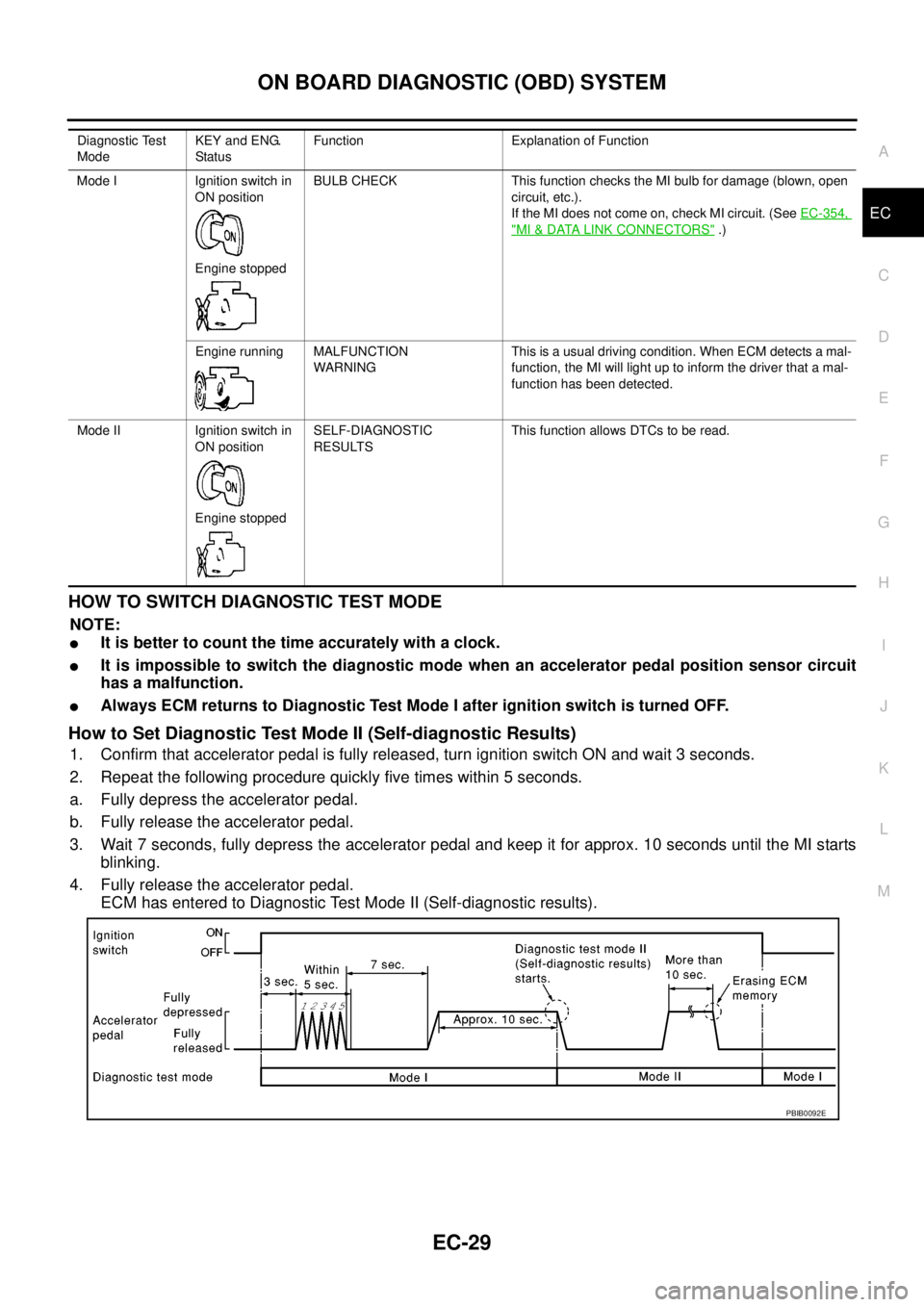
HOWTOSWITCHDIAGNOSTICTESTMODE
NOTE:
lIt is better to count the time accurately with a clock.
lIt is impossible to switch the diagnostic mode when an accelerator pedal position sensor circuit
has a malfunction.
lAlways ECM returns to Diagnostic Test Mode I after ignition switch is turned OFF.
How to Set Diagnostic Test Mode II (Self-diagnostic Results)
1. Confirm that accelerator pedal is fully released, turn ignition switch ON and wait 3 seconds.
2. Repeat the following procedure quickly five times within 5 seconds.
a. Fully depress the accelerator pedal.
b. Fully release the accelerator pedal.
3. Wait 7 seconds, fully depress the accelerator pedal and keep it for approx. 10 seconds until the MI starts
blinking.
4. Fully release the accelerator pedal.
ECM has entered to Diagnostic Test Mode II (Self-diagnostic results).
Diagnostic Test
ModeKEY and ENG.
Statu sFunction Explanation of Function
Mode I Ignition switch in
ON position
Engine stoppedBULB CHECK This function checks the MI bulb for damage (blown, open
circuit, etc.).
If the MI does not come on, check MI circuit. (SeeEC-354,
"MI&DATA LINK CONNECTORS".)
Engine running MALFUNCTION
WARNINGThis is a usual driving condition. When ECM detects a mal-
function, the MI will light up to inform the driver that a mal-
function has been detected.
Mode II Ignition switch in
ON position
Engine stoppedSELF-DIAGNOSTIC
RESULTSThis function allows DTCs to be read.
PBIB0092E
Page 1448 of 3171

EM-66
CAMSHAFT
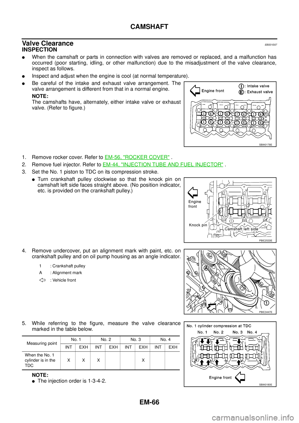
Valve Clearance
EBS01E67
INSPECTION
lWhen the camshaft or parts in connection with valves are removed or replaced, and a malfunction has
occurred (poor starting, idling, or other malfunction) due to the misadjustment of the valve clearance,
inspect as follows.
lInspect and adjust when the engine is cool (at normal temperature).
lBe careful of the intake and exhaust valve arrangement. The
valve arrangement is different from that in a normal engine.
NOTE:
The camshafts have, alternately, either intake valve or exhaust
valve. (Refer to figure.)
1. Remove rocker cover. Refer toEM-56, "
ROCKER COVER".
2. Remove fuel injector. Refer toEM-44, "
INJECTION TUBE AND FUEL INJECTOR".
3. Set the No. 1 piston to TDC on its compression stroke.
lTurn crankshaft pulley clockwise so that the knock pin on
camshaft left side faces straight above. (No position indicator,
etc. is provided on the crankshaft pulley.)
4. Remove undercover, put an alignment mark with paint, etc. on
crankshaft pulley and on oil pump housing as an angle indicator.
5. While referring to the figure, measure the valve clearance
marked in the table below.
NOTE:
lThe injection order is 1-3-4-2.
SBIA0178E
PBIC2533E
1 : Crankshaft pulley
A : Alignment mark
: Vehicle front
PBIC3447E
Measuring pointNo. 1 No. 2 No. 3 No. 4
INT EXH INT EXH INT EXH INT EXH
When the No. 1
cylinder is in the
TDCXXX X
SBIA0180E
Page 1449 of 3171

CAMSHAFT
EM-67
C
D
E
F
G
H
I
J
K
L
MA
EM
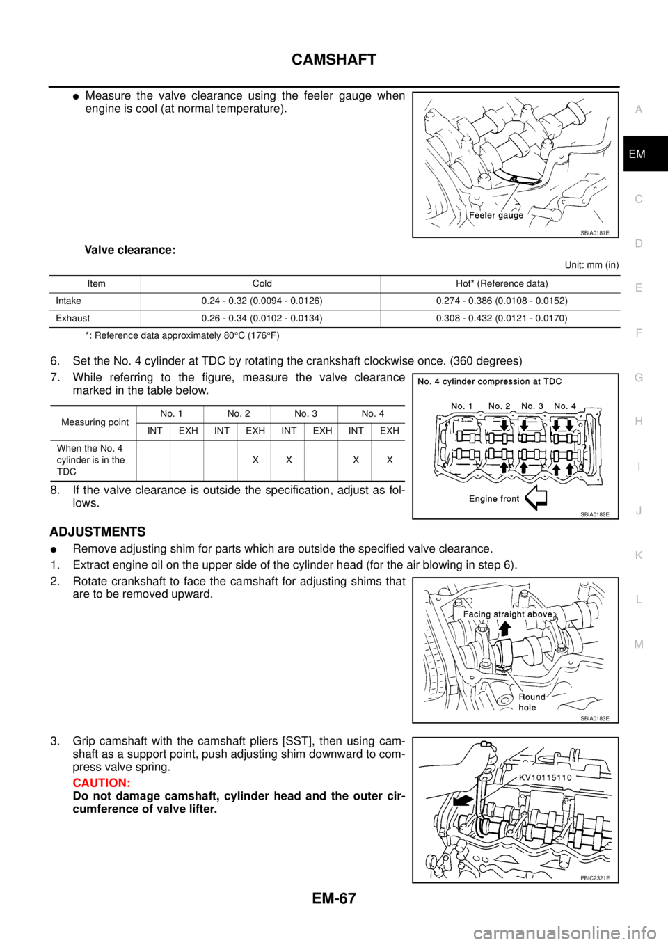
lMeasure the valve clearance using the feeler gauge when
engine is cool (at normal temperature).
Valve clearance:
Unit: mm (in)
*: Reference data approximately 80°C(176°F)
6. Set the No. 4 cylinder at TDC by rotating the crankshaft clockwise once. (360 degrees)
7. While referring to the figure, measure the valve clearance
marked in the table below.
8. If the valve clearance is outside the specification, adjust as fol-
lows.
ADJUSTMENTS
lRemove adjusting shim for parts which are outside the specified valve clearance.
1. Extract engine oil on the upper side of the cylinder head (for the air blowing in step 6).
2. Rotate crankshaft to face the camshaft for adjusting shims that
are to be removed upward.
3. Grip camshaft with the camshaft pliers [SST], then using cam-
shaft as a support point, push adjusting shim downward to com-
press valve spring.
CAUTION:
Do not damage camshaft, cylinder head and the outer cir-
cumference of valve lifter.
SBIA0181E
Item Cold Hot* (Reference data)
Intake 0.24 - 0.32 (0.0094 - 0.0126) 0.274 - 0.386 (0.0108 - 0.0152)
Exhaust 0.26 - 0.34 (0.0102 - 0.0134) 0.308 - 0.432 (0.0121 - 0.0170)
Measuring pointNo. 1 No. 2 No. 3 No. 4
INT EXH INT EXH INT EXH INT EXH
When the No. 4
cylinder is in the
TDCXX XX
SBIA0182E
SBIA0183E
PBIC2321E