2005 NISSAN NAVARA fog light
[x] Cancel search: fog lightPage 573 of 3171

BCM (BODY CONTROL MODULE)
BCS-7
C
D
E
F
G
H
I
J
L
MA
B
BCS
BCM STATUS CONTROL
BCM changes its status depending on the operation status in order to save power consumption.
1. CAN communication status
lWith ignition switch ON, CAN communicates with other control units normally.
lControl by BCM is being operated properly.
lWhen ignition switch is OFF, switching to sleep mode is possible.
lEven when ignition switch is OFF, if CAN communication with IPDM E/R and combination meter is
active, CAN communication status is active.
2. Sleep transient status
lThis status shuts down CAN communication when ignition switch is turned OFF.
lIt transmits sleep request signal to IPDM E/R and combination meter.
lTwo seconds after CAN communication of all control units stops, CAN communication switches to inac-
tive status.
3. CAN communication inactive status
lWith ignition switch OFF, CAN communication is not active.
lWith ignition switch OFF, control performed only by BCM is active.
lThree seconds after CAN communication of all control units stops, CAN communication switches to
inactive status.
4. Sleep status
lBCM is activated with low current consumption mode.
lCAN communication is not active.
lWhen CAN communication operation is detected, it switches to CAN communication status.
lWhen a state of the following switches changes, it switches to CAN communication state:
–Key switch
–Hazard switch
–Door lock/unlock switch
–Front door switch (driver side, passenger side)
–Rear door switch (LH, RH) (double cab)
–Rear door switch (driver side, passenger side) No.1 (king cab)
–Rear door switch (driver side, passenger side) No.2 (king cab)
–Combination switch (passing, lighting switch 1st position, front fog lamp)
–Keyfob (lock/unlock signal)
–Door lock assembly LH (key cylinder switch)
lWhen control performed only by BCM is required by switch, it shifts to CAN communication inactive
mode.
lStatus of combination switch reading function is changed.
Page 574 of 3171

BCS-8
BCM (BODY CONTROL MODULE)
SYSTEMS CONTROLLED BY BCM DIRECTLY
NOTE:
Power supply only. No system control.
SYSTEMS CONTROLLED BY BCM AND IPDM E/R
SYSTEMS CONTROLLED BY BCM AND COMBINATION METER
System Reference
Power door lock
lBL-21, "POWER DOOR LOCK SYSTEM"
lBL-55, "POWER DOOR LOCK—SUPER LOCK—"
Remote keyless entryBL-89, "MULTI-REMOTE CONTROL SYSTEM"
Power windowNOTEGW-15, "POWER WINDOW SYSTEM"
Sunroof systemNOTERF-10, "SUNROOF"
Room lamp timerLT-145, "INTERIOR ROOM LAMP"
Rear fog lampLT- 8 7 , "REAR FOG LAMP"
System Reference
NATSBL-170, "
NATS(Nissan Anti-Theft System)"
HeadlampLT- 5 , "HEADLAMP -CONVENTIONAL TYPE-"
Daytime light systemLT-31, "HEADLAMP - DAYTIME LIGHT SYSTEM -"
Auto light systemLT-49, "AUTO LIGHT SYSTEM"
Parking, license plate and tail lampsLT-125, "PARKING, LICENSE PLATE AND TAIL LAMPS"
Front fog lampLT-71, "FRONT FOG LAMP"
Front wiper, washerWW-4, "FRONT WIPER AND WASHER SYSTEM"
Headlamp washerWW-39, "HEADLAMP WASHER"
Rear window defoggerGW-47, "REAR WINDOW DEFOGGER"
System Reference
Warning chimeDI-51, "
WARNING CHIME"
Turn signal and hazard warning lampsLT-97, "TURN SIGNAL AND HAZARD WARNING LAMPS"
Page 575 of 3171

BCM (BODY CONTROL MODULE)
BCS-9
C
D
E
F
G
H
I
J
L
MA
B
BCS
MAJOR COMPONENTS AND CONTROL SYSTEM
CAN Communication System DescriptionEKS00PA2
Refer toLAN-23, "CAN COMMUNICATION".
System Input Output
Remote keyless entry system Keyfob
lAll-door locking actuator
lTurn signal lamp (LH, RH)
lCombination meter (Turn signal
lamp)
Power door lock system Door lock/unlock switch All-door locking actuator
Power supply (IGN) to power win-
dow and sunroofIgnition power supply Power window and sunroof system
Power supply (BAT) to power
window and sunroofBattery power supply Power window and sunroof system
Headlamp Combination switch IPDM E/R
Tail lamp Combination switch IPDM E/R
Front fog lamp Combination switch IPDM E/R
Rear fog lamp Combination switch
lRear fog lamp
lCombination meter
Turn signal lamp Combination switch
lTurn signal lamp
lCombination meter
Hazard lamp Hazard switch
lTurn signal lamp
lCombination meter
Room lamp timer
lKey switch
lKeyfob
lDoor lock/unlock switch
lFront door switch driver side
lAll-door switchInterior room lamp
Light warning chime
lCombination switch
lKey switch
lFront door switch driver sideCombination meter (warning buzzer)
Rain-sensing intermittent wiper
lCombination switch
lLight and rain sensorIPDM E/R
Vehicle-speed-sensing intermit-
tent wiper
lCombination switch
lCombination meterIPDM E/R
Headlamp washer Combination switch IPDM E/R
Rear window defogger
lRear window defogger switch
lIgnition switch (ACC, ON)IPDM E/R
A/C switch signal Front air control ECM
Blower fan switch signal Front air control ECM
Page 969 of 3171

WARNING CHIME
DI-59
C
D
E
F
G
H
I
J
L
MA
B
DI
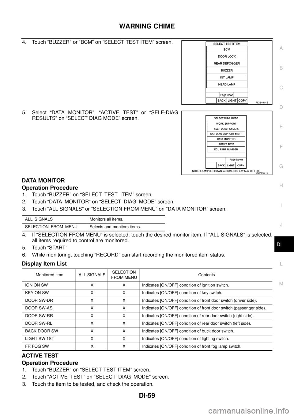
4. Touch “BUZZER” or “BCM” on “SELECT TEST ITEM” screen.
5. Select “DATA MONITOR”, “ACTIVE TEST” or “SELF-DIAG
RESULTS” on “SELECT DIAG MODE” screen.
DATA MONITOR
Operation Procedure
1. Touch “BUZZER” on “SELECT TEST ITEM” screen.
2. Touch “DATA MONITOR” on “SELECT DIAG MODE” screen.
3. Touch “ALL SIGNALS” or “SELECTION FROM MENU” on “DATA MONITOR” screen.
4. If “SELECTION FROM MENU” is selected, touch the desired monitor item. If “ALL SIGNALS” is selected,
all items required to control are monitored.
5. Touch “START”.
6. While monitoring, touching “RECORD” can start recording the monitored item status.
Display Item List
ACTIVE TEST
Operation Procedure
1. Touch “BUZZER” on “SELECT TEST ITEM” screen.
2. Touch “ACTIVE TEST” on “SELECT DIAG MODE” screen.
3. Touch the item to be tested, and check the operation.
PKIB4914E
BCIA0031E
ALL SIGNALS Monitors all items.
SELECTION FROM MENU Selects and monitors items.
Monitored item ALL SIGNALSSELECTION
FROM MENUContents
IGN ON SW X X Indicates [ON/OFF] condition of ignition switch.
KEY ON SW X X Indicates [ON/OFF] condition of key switch.
DOOR SW-DR X X Indicates [ON/OFF] condition of front door switch (driver side).
DOOR SW-AS X X Indicates [ON/OFF] condition of front door switch (passenger side).
DOOR SW-RR X X Indicates [ON/OFF] condition of rear door switch (right side).
DOOR SW-RL X X Indicates [ON/OFF] condition of rear door switch (left side).
BACK DOOR SW X X Indicates [ON/OFF] condition of buck door switch.
LIGHT SW 1ST X X Indicates [ON/OFF] condition of lighting switch.
FR FOG SW X X Indicates [ON/OFF] condition of front fog lamp switch.
Page 1018 of 3171

EC-38
TROUBLE DIAGNOSIS
Basic Inspection
EBS01KCV
Precaution:
Perform Basic Inspection without electrical or mechanical loads applied;
lHeadlamp switch is OFF.
lOn vehicles equipped with daytime light systems, set lighting switch to the 1st position to light
only small lamps.
lAir conditioner switch is OFF.
lHeater fan switch is OFF.
lRear defogger switch is OFF.
lHeat up switch is OFF.
lSteering wheel is in the straight-ahead position, etc.
1.INSPECTION START
1. Check service records for any recent repairs that may indicate a related incident.
2. Check the current need for scheduled maintenance, especially for fuel filter and air cleaner filter. Refer to
MA-8, "
PERIODIC MAINTENANCE".
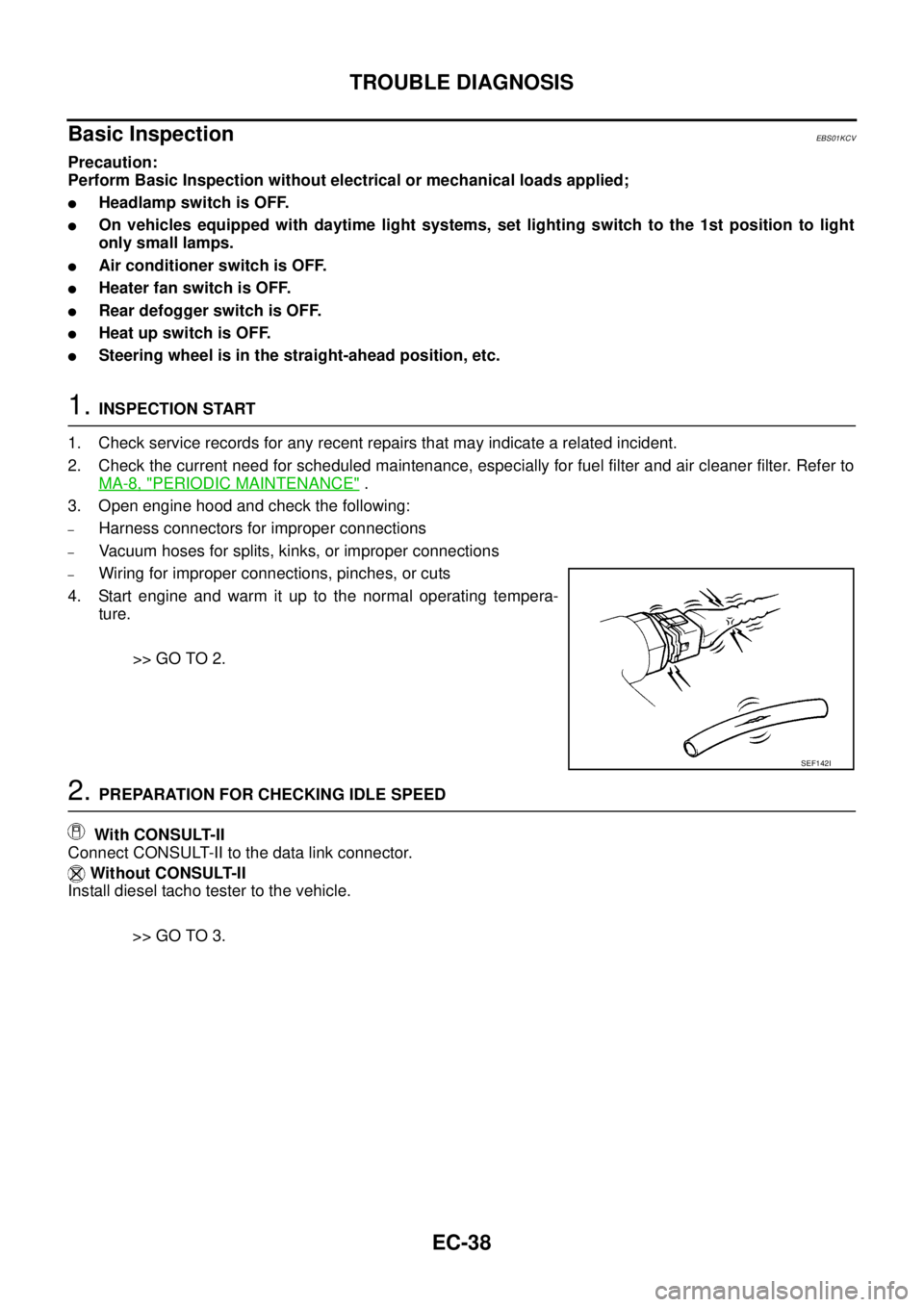
3. Open engine hood and check the following:
–Harness connectors for improper connections
–Vacuum hoses for splits, kinks, or improper connections
–Wiring for improper connections, pinches, or cuts
4. Start engine and warm it up to the normal operating tempera-
ture.
>> GO TO 2.
2.PREPARATION FOR CHECKING IDLE SPEED
With CONSULT-II
Connect CONSULT-II to the data link connector.
Without CONSULT-II
Install diesel tacho tester to the vehicle.
>> GO TO 3.
SEF142I
Page 1047 of 3171

TROUBLE DIAGNOSIS
EC-67
C
D
E
F
G
H
I
J
K
L
MA
EC
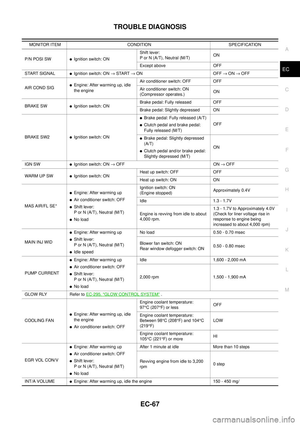
P/N POSI SWlIgnition switch: ONShift lever:
P or N (A/T), Neutral (M/T)ON
Except above OFF
START SIGNAL
lIgnition switch: ON®START®ON OFF®ON®OFF
AIRCONDSIG
lEngine: After warming up, idle
the engineAir conditioner switch: OFF OFF
Air conditioner switch: ON
(Compressor operates.)ON
BRAKE SW
lIgnition switch: ONBrake pedal: Fully released OFF
Brake pedal: Slightly depressed ON
BRAKE SW2
lIgnition switch: ON
lBrake pedal: Fully released (A/T)
lClutch pedal and brake pedal:
Fully released (M/T)OFF
lBrake pedal: Slightly depressed
(A/T)
lClutch pedal and/or brake pedal:
Slightly depressed (M/T)ON
IGN SW
lIgnition switch: ON®OFF ON®OFF
WARM UP SW
lIgnition switch: ONHeat up switch: OFF OFF
Heat up switch: ON ON
MAS AIR/FL SE*
lEngine: After warming up
lAir conditioner switch: OFF
lShift lever:
P or N (A/T), Neutral (M/T)
lNo loadIgnition switch: ON
(Engine stopped)Approximately 0.4V
Idle 1.3 - 1.7V
Engine is revving from idle to about
4,000 rpm.1.3 - 1.7V to Approximately 4.0V
(Check for liner voltage rise in
response to engine being
increased to about 4,000 rpm)
MAIN INJ WID
lEngine: After warming up
lShift lever:
P or N (A/T), Neutral (M/T)
lIdle speedNo load 0.50 - 0.70 msec
Blower fan switch: ON
Rear window defogger switch: ON0.50 - 0.80 msec
PUMP CURRENT
lEngine: After warming up
lAir conditioner switch: OFF
lShift lever:
P or N (A/T), Neutral (M/T)
lNo loadIdle 1,600 - 2,000 mA
2,000 rpm 1,500 - 1,900 mA
GLOW RLY Refer toEC-295, "
GLOW CONTROL SYSTEM".
COOLING FAN
lEngine: After warming up, idle
the engine
lAir conditioner switch: OFFEngine coolant temperature:
97°C (207°F) or lessOFF
Engine coolant temperature:
Between 98°C(208°F) and 104°C
(219°F)LOW
Engine coolant temperature:
105°C(221°F) or moreHI
EGR VOL CON/V
lEngine: After warming up
lAir conditioner switch: OFF
lShift lever:
P or N (A/T), Neutral (M/T)
lNo loadAfter 1 minute at idle More than 10 steps
Revving engine from idle to 3,200
rpm0step
INT/A VOLUME
lEngine: After warming up, idle the engine 150 - 450 mg/ MONITOR ITEM CONDITION SPECIFICATION
Page 1337 of 3171

SERVICE DATA AND SPECIFICATIONS (SDS)
EC-357
C
D
E
F
G
H
I
J
K
L
MA
EC
SERVICE DATA AND SPECIFICATIONS (SDS)PFP:00100
General SpecificationsEBS01KN4
*: Under the following conditions:
lHeat up switch: OFF
lAir conditioner switch: OFF
lElectric load: OFF (Lights, heater fan & rear window defogger)
lSteering wheel: Kept in straight-ahead position
Mass Air Flow SensorEBS01KN5
*: Engine is warmed up to normal operating temperature and running under no load.
Intake Air Temperature SensorEBS01KN6
Engine Coolant Temperature SensorEBS01KN7
Fuel Rail Pressure SensorEBS01KN8
Fuel InjectorEBS01KN9
Glow PlugEBS01KNA
EGR Volume Control ValveEBS01KNB
Crankshaft Position SensorEBS01KNC
Refer toEC-164, "Component Inspection".
Camshaft Position SensorEBS01KND
Refer toEC-175, "Component Inspection".
Target idle speedA/T No load* (in P or N position)
750±25 rpm
M/T No load* (in Neutral position)
Air conditioner: ONA/T In P or N position 750 rpm or more
M/T In Neutral position 800 rpm or more
Maximum engine speed4,900 rpm
Supply voltageBattery voltage (11 - 14V)
Ignition switch ON (Engine stopped.) Approx. 0.4V
Idle (Engine is warmed up to normal operating temperature.) 1.3 - 1.7V *
Temperature°C(°F) Resistance kW
25 (77)1.800 - 2.200
80 (176)0.283 - 0.359
Temperature°C(°F) Resistance kW
20 (68)2.1 - 2.9
50 (122)0.68 - 1.00
90 (194)0.236 - 0.260
Supply voltageApproximately 5V
Idle (Engine is warmed up to normal operating temperature.) 1.7 - 2.0V
2,000 rpm (Engine is warmed up to normal operating tempera-
ture.)2.0 - 2.3V
Resistance [at 10 - 60°C (50 - 140°F)] 0.2 - 0.8W
Resistance [at 25°C(77°F)] Approximately 0.8W
Resistance [at 25°C(77°F)] 13 - 17W
Page 1742 of 3171

GW-56
REAR WINDOW DEFOGGER
Trouble Diagnoses Symptom Chart
EIS00B8N
lMake sure other systems using the signal of the following systems operate normally.
BCM Power Supply and Ground Circuit CheckEIS00B8O
First perform the “SELF-DIAG RESULTS” in “BCM” with CONSULT-II, when perform the each trouble
diagnosis. Refer toBCS-16, "
CAN Communication Inspection Using CONSULT-II (Self-Diagnosis)".
1.CHECK FUSE
lCheck 10A fuse [No. 1, located in the fuse block (J/B)]
lCheck 50A fusible link (letterGlocated in the fuse and fusible link box)
NOTE:
Refer toGW-47, "
Component Parts and Harness Connector Location".
OK or NG
OK >> GO TO 2.
NG >> If fuse is blown, be sure to eliminate cause of malfunction before installing new fuse. Refer toPG-
4, "POWER SUPPLY ROUTING CIRCUIT".
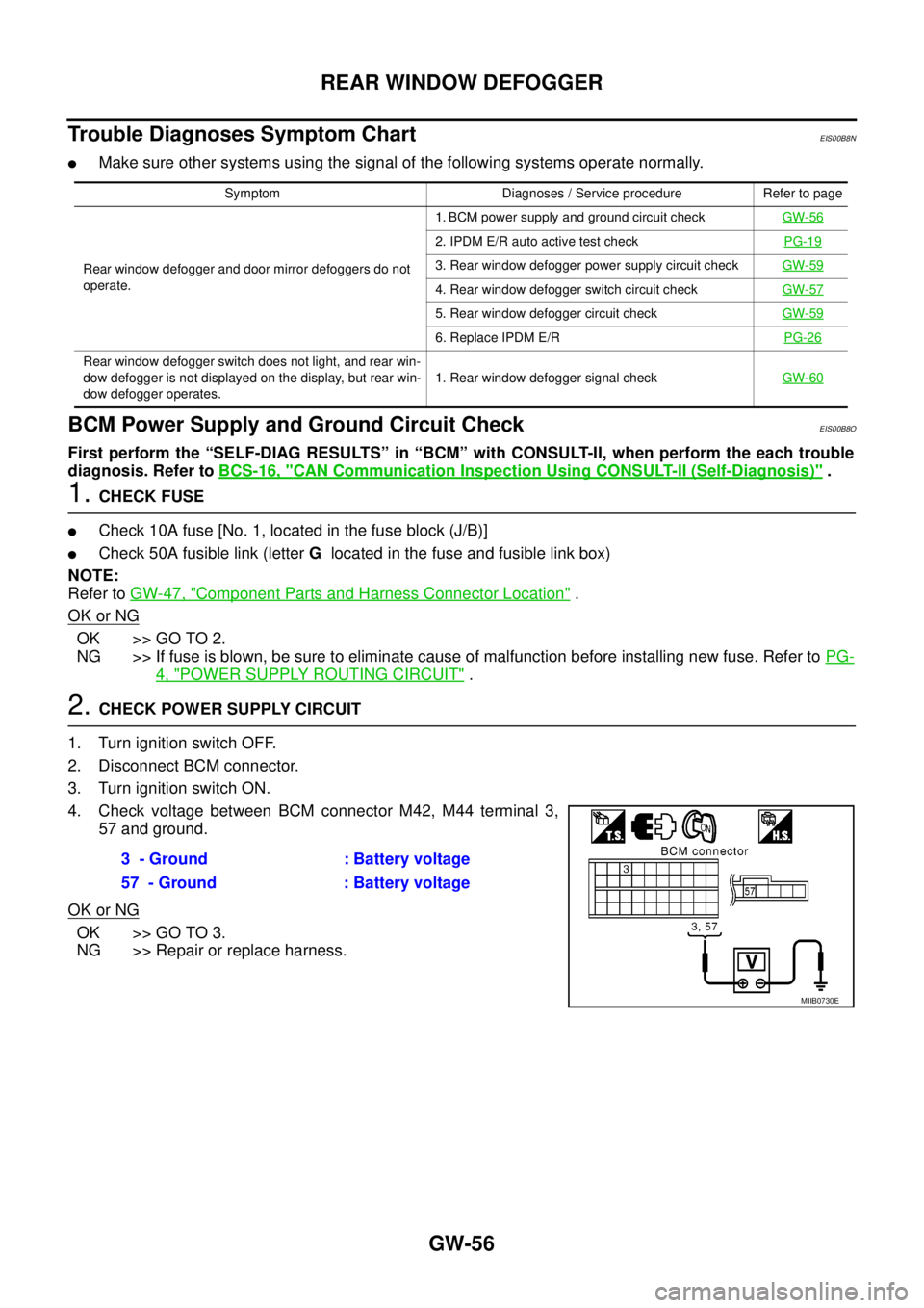
2.CHECK POWER SUPPLY CIRCUIT
1. Turn ignition switch OFF.
2. Disconnect BCM connector.
3. Turn ignition switch ON.
4. Check voltage between BCM connector M42, M44 terminal 3,
57 and ground.
OK or NG
OK >> GO TO 3.
NG >> Repair or replace harness.
Symptom Diagnoses / Service procedure Refer to page
Rear window defogger and door mirror defoggers do not
operate.1. BCM power supply and ground circuit checkGW-56
2. IPDM E/R auto active test checkPG-19
3. Rear window defogger power supply circuit checkGW-59
4. Rear window defogger switch circuit checkGW-57
5. Rear window defogger circuit checkGW-59
6. Replace IPDM E/RPG-26
Rear window defogger switch does not light, and rear win-
dow defogger is not displayed on the display, but rear win-
dow defogger operates.1. Rear window defogger signal checkGW-60
3 - Ground : Battery voltage
57 - Ground : Battery voltage
MIIB0730E