2005 NISSAN NAVARA wheel bolts
[x] Cancel search: wheel boltsPage 476 of 3171
ATC-142
REFRIGERANT LINES
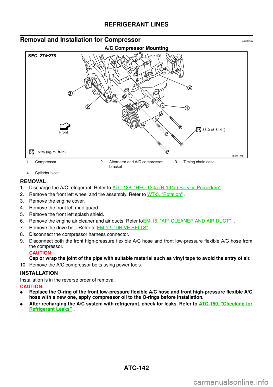
Removal and Installation for Compressor
EJS006CN
A/C Compressor Mounting
REMOVAL
1. Discharge the A/C refrigerant. Refer toATC-138, "HFC-134a (R-134a) Service Procedure".
2. Remove the front left wheel and tire assembly. Refer toWT-5, "
Rotation".
3. Remove the engine cover.
4. Remove the front left mud guard.
5. Remove the front left splash shield.
6. Remove the engine air cleaner and air ducts. Refer toEM-15, "
AIR CLEANER AND AIR DUCT".
7. Remove the drive belt. Refer toEM-12, "
DRIVE BELTS".
8. Disconnect the compressor harness connector.
9. Disconnect both the front high-pressure flexible A/C hose and front low-pressure flexible A/C hose from
the compressor.
CAUTION:
Cap or wrap the joint of the pipe with suitable material such as vinyl tape to avoid the entry of air.
10. Remove the A/C compressor bolts using power tools.
INSTALLATION
Installation is in the reverse order of removal.
CAUTION:
lReplace the O-ring of the front low-pressure flexible A/C hose and front high-pressure flexible A/C
hose with a new one, apply compressor oil to the O-rings before installation.
lAfter recharging the A/C system with refrigerant, check for leaks. Refer toATC-150, "Checking for
Refrigerant Leaks".
MJIB0179E
1. Compressor 2. Alternator and A/C compressor
bracket3. Timing chain case
4. Cylinder block
Page 812 of 3171
BR-26
FRONT DISC BRAKE
Removal and Installation of Brake Caliper Assembly
EFS005T1
REMOVAL
1. Remove tyre from vehicle.
2. Fasten disc rotor using wheel nut.
CAUTION:
Align the matching marks of disc rotor and wheel hub, which were marked at the time of removal
when reusing disc rotor.
3. Drain brake fluid. Refer toBR-10, "
Drain and Refill".
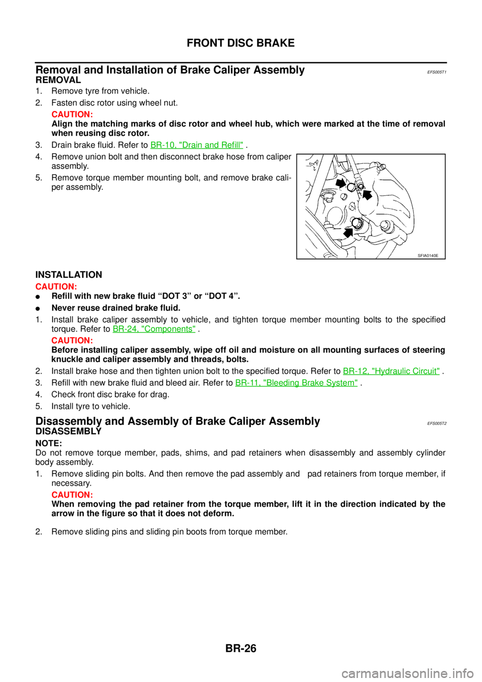
4. Remove union bolt and then disconnect brake hose from caliper
assembly.
5. Remove torque member mounting bolt, and remove brake cali-
per assembly.
INSTALLATION
CAUTION:
lRefill with new brake fluid “DOT 3” or “DOT 4”.
lNever reuse drained brake fluid.
1. Install brake caliper assembly to vehicle, and tighten torque member mounting bolts to the specified
torque. Refer toBR-24, "
Components".
CAUTION:
Before installing caliper assembly, wipe off oil and moisture on all mounting surfaces of steering
knuckle and caliper assembly and threads, bolts.
2. Install brake hose and then tighten union bolt to the specified torque. Refer toBR-12, "
Hydraulic Circuit".
3. Refill with new brake fluid and bleed air. Refer toBR-11, "
Bleeding Brake System".
4. Check front disc brake for drag.
5. Install tyre to vehicle.
Disassembly and Assembly of Brake Caliper AssemblyEFS005T2
DISASSEMBLY
NOTE:
Do not remove torque member, pads, shims, and pad retainers when disassembly and assembly cylinder
body assembly.
1. Remove sliding pin bolts. And then remove the pad assembly and pad retainers from torque member, if
necessary.
CAUTION:
When removing the pad retainer from the torque member, lift it in the direction indicated by the
arrow in the figure so that it does not deform.
2. Remove sliding pins and sliding pin boots from torque member.
SFIA0140E
Page 820 of 3171
BR-34
REAR DRUM BRAKE
Removal and Installation of Wheel Cylinder
EFS006AH
REMOVAL
1. Drain brake fluid. Refer toBR-10, "Drain and Refill".
2. Remove rear brake shoe assembly.
3. Remove brake tube from the wheel cylinder.
4. Remove bolts on the wheel cylinder, and then remove wheel cylinder from the back plate.
INSTALLATION
lInstallation is the reverse order of removal. Tighten bolts to the specified torque. Refer toBR-30, "Compo-
nents".
lRefill with new brake fluid and bleed air. Refer toBR-11, "Bleeding Brake System".
Disassembly and Assembly of Wheel CylinderEFS006AI
DISASSEMBLY
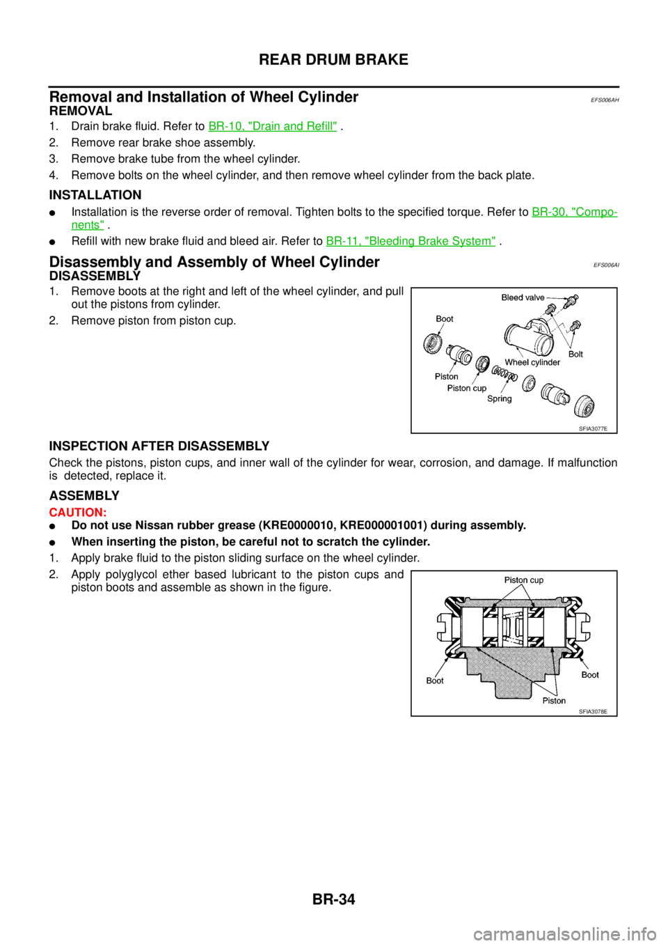
1. Remove boots at the right and left of the wheel cylinder, and pull
out the pistons from cylinder.
2. Remove piston from piston cup.
INSPECTION AFTER DISASSEMBLY
Check the pistons, piston cups, and inner wall of the cylinder for wear, corrosion, and damage. If malfunction
is detected, replace it.
ASSEMBLY
CAUTION:
lDo not use Nissan rubber grease (KRE0000010, KRE000001001) during assembly.
lWhen inserting the piston, be careful not to scratch the cylinder.
1. Apply brake fluid to the piston sliding surface on the wheel cylinder.
2. Apply polyglycol ether based lubricant to the piston cups and
piston boots and assemble as shown in the figure.
SFIA3077E
SFIA3078E
Page 860 of 3171
![NISSAN NAVARA 2005 Repair Workshop Manual BRC-38
[ABS]
WHEEL SENSORS
REMOVAL
Pay attention to the following when removing wheel sensor.
CAUTION:
lAs much as possible, avoid rotating wheel sensor when removing it. Pull wheel sensors out with-
NISSAN NAVARA 2005 Repair Workshop Manual BRC-38
[ABS]
WHEEL SENSORS
REMOVAL
Pay attention to the following when removing wheel sensor.
CAUTION:
lAs much as possible, avoid rotating wheel sensor when removing it. Pull wheel sensors out with-](/manual-img/5/57362/w960_57362-859.png)
BRC-38
[ABS]
WHEEL SENSORS
REMOVAL
Pay attention to the following when removing wheel sensor.
CAUTION:
lAs much as possible, avoid rotating wheel sensor when removing it. Pull wheel sensors out with-
out pulling on sensor harness.
lTake care to avoid damaging wheel sensor edges or rotor teeth. Remove wheel sensor first before
removing front or rear wheel hub. This is to avoid damage to wheel sensor wiring and loss of sen-
sor function.
INSTALLATION
Pay attention to the following when installing wheel sensor. Tighten installation bolts and nuts to the specified
torques.
lWhen installing, make sure there is no foreign material such as iron chips on and in the mounting hole of
the wheel sensor. Make sure no foreign material has been caught in the sensor rotor. Remove any foreign
material and clean the mount.
lWhen installing wheel sensor, be sure to press rubber grommets in until they lock at locations shown
above in figure. When installed, harness must not be twisted.
Page 881 of 3171
CLUTCH DISC, CLUTCH COVER AND FLYWHEEL
CL-17
D
E
F
G
H
I
J
K
L
MA
B
CL
CLUTCH DISC, CLUTCH COVER AND FLYWHEELPFP:30100
Removal and InstallationECS00ICR
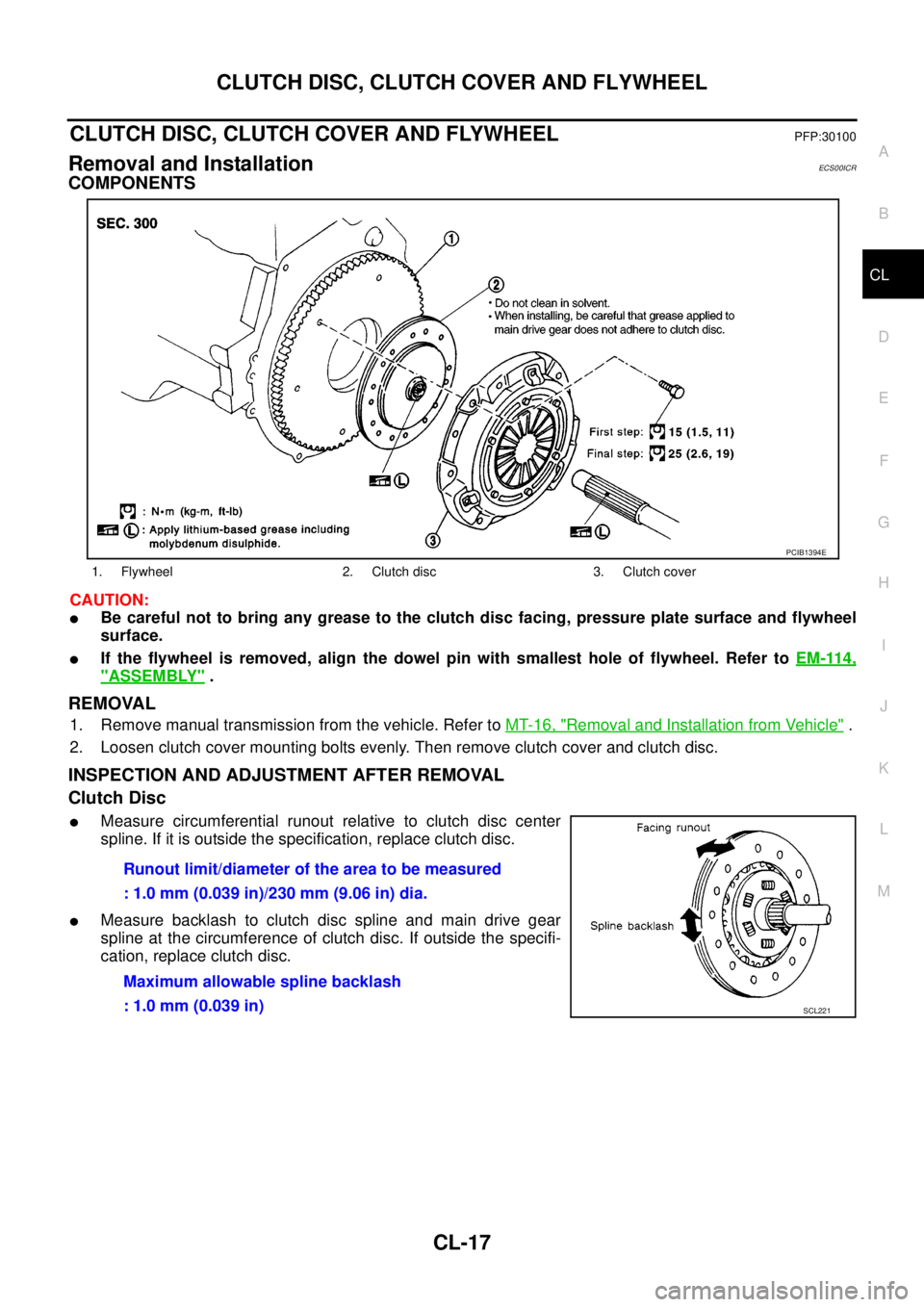
COMPONENTS
CAUTION:
lBe careful not to bring any grease to the clutch disc facing, pressure plate surface and flywheel
surface.
lIf the flywheel is removed, align the dowel pin with smallest hole of flywheel. Refer toEM-114,
"ASSEMBLY".
REMOVAL
1. Remove manual transmission from the vehicle. Refer toMT-16, "Removal and Installation from Vehicle".
2. Loosen clutch cover mounting bolts evenly. Then remove clutch cover and clutch disc.
INSPECTION AND ADJUSTMENT AFTER REMOVAL
Clutch Disc
lMeasure circumferential runout relative to clutch disc center
spline. If it is outside the specification, replace clutch disc.
lMeasure backlash to clutch disc spline and main drive gear
spline at the circumference of clutch disc. If outside the specifi-
cation, replace clutch disc.
1. Flywheel 2. Clutch disc 3. Clutch cover
PCIB1394E
Runout limit/diameter of the area to be measured
: 1.0 mm (0.039 in)/230 mm (9.06 in) dia.
Maximum allowable spline backlash
: 1.0 mm (0.039 in)
SCL221
Page 883 of 3171
CLUTCH DISC, CLUTCH COVER AND FLYWHEEL
CL-19
D
E
F
G
H
I
J
K
L
MA
B
CL
2. Install clutch disc using the clutch aligning bar.
3. Install clutch cover. Pre-tighten clutch cover mounting bolts.
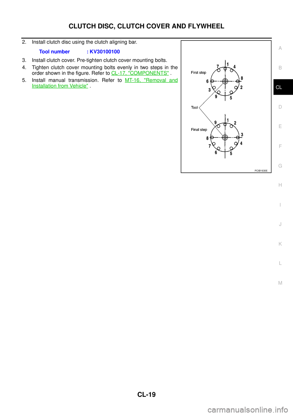
4. Tighten clutch cover mounting bolts evenly in two steps in the
order shown in the figure. Refer toCL-17, "
COMPONENTS".
5. Install manual transmission. Refer toMT-16, "
Removal and
Installation from Vehicle". Tool number : KV30100100
PCIB1630E
Page 1488 of 3171
EM-106
ENGINE ASSEMBLY
ENGINE ASSEMBLY
PFP:10001
ComponentsEBS01EV6
Removal and InstallationEBS01E6D
WARNING:
lSituate vehicle on a flat and solid surface.
lPlace chocks at front and back of rear wheels.
lFor engines not equipped with engine slingers, attach proper slingers and bolts described in
PARTS CATALOG.
CAUTION:
lAlways be careful to work safely, avoid forceful or uninstructed operations.
lDo not start working until exhaust system and engine coolant are cool enough.
lIf items or work required are not covered by the engine main body section, refer to the applicable
sections.
lAlways use the support point specified for lifting.
lUse either 2-pole lift type or separate type lift as best you can. If board-on type is used for
unavoidable reasons, support at the rear axle jacking point with transmission jack or similar tool
before starting work, in preparation for the backward shift of center of gravity.
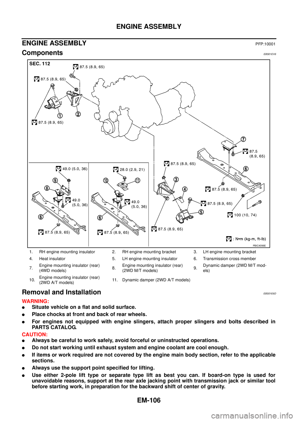
1. RH engine mounting insulator 2. RH engine mounting bracket 3. LH engine mounting bracket
4. Heat insulator 5. LH engine mounting insulator 6. Transmission cross member
7.Engine mounting insulator (rear)
(4WD models)8.Engine mounting insulator (rear)
(2WD M/T models)9.Dynamic damper (2WD M/T mod-
els)
10.Engine mounting insulator (rear)
(2WD A/T models)11. Dynamic damper (2WD A/T models)
PBIC4096E
Page 1493 of 3171
CYLINDER BLOCK
EM-111
C
D
E
F
G
H
I
J
K
L
MA
EM
lRefer toGI-10, "Components"for symbol marks in the figure.
Disassembly and AssemblyEBS01E6E
DISASSEMBLY
1. Remove engine from the vehicle. Refer toEM-106, "ENGINE ASSEMBLY".
2. Remove clutch cover and disk. (M/T models) Refer toCL-17,
"CLUTCH DISC, CLUTCH COVER AND FLYWHEEL".
3. If they need to be replaced, replace pilot bush (M/T models) or
pilot converter (A/T models).
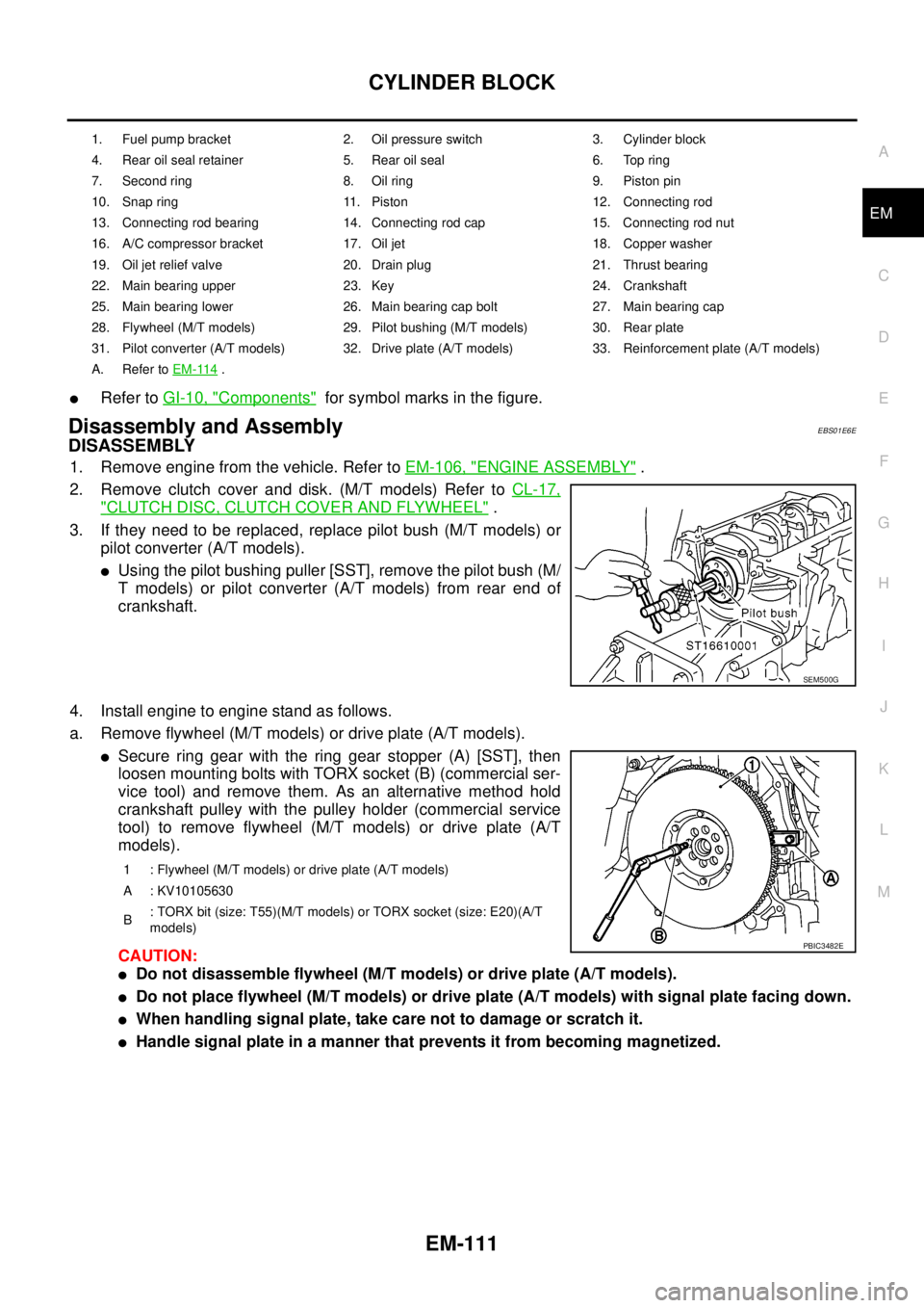
lUsing the pilot bushing puller [SST], remove the pilot bush (M/
T models) or pilot converter (A/T models) from rear end of
crankshaft.
4. Install engine to engine stand as follows.
a. Remove flywheel (M/T models) or drive plate (A/T models).
lSecure ring gear with the ring gear stopper (A) [SST], then
loosen mounting bolts with TORX socket (B) (commercial ser-
vice tool) and remove them. As an alternative method hold
crankshaft pulley with the pulley holder (commercial service
tool) to remove flywheel (M/T models) or drive plate (A/T
models).
CAUTION:
lDo not disassemble flywheel (M/T models) or drive plate (A/T models).
lDo not place flywheel (M/T models) or drive plate (A/T models) with signal plate facing down.
lWhen handling signal plate, take care not to damage or scratch it.
lHandle signal plate in a manner that prevents it from becoming magnetized.
1. Fuel pump bracket 2. Oil pressure switch 3. Cylinder block
4. Rear oil seal retainer 5. Rear oil seal 6. Top ring
7. Second ring 8. Oil ring 9. Piston pin
10. Snap ring 11. Piston 12. Connecting rod
13. Connecting rod bearing 14. Connecting rod cap 15. Connecting rod nut
16. A/C compressor bracket 17. Oil jet 18. Copper washer
19. Oil jet relief valve 20. Drain plug 21. Thrust bearing
22. Main bearing upper 23. Key 24. Crankshaft
25. Main bearing lower 26. Main bearing cap bolt 27. Main bearing cap
28. Flywheel (M/T models) 29. Pilot bushing (M/T models) 30. Rear plate
31. Pilot converter (A/T models) 32. Drive plate (A/T models) 33. Reinforcement plate (A/T models)
A. Refer toEM-114
.
SEM500G
1 : Flywheel (M/T models) or drive plate (A/T models)
A : KV10105630
B: TORX bit (size: T55)(M/T models) or TORX socket (size: E20)(A/T
models)
PBIC3482E