2005 NISSAN NAVARA service reset
[x] Cancel search: service resetPage 348 of 3171

ATC-14
PRECAUTIONS
SERVICE COUPLERS
Never attempt to connect HFC-134a (R-134a) service couplers to an
CFC-12 (R-12) A/C system. The HFC-134a (R-134a) couplers will
not properly connect to the CFC-12 (R-12) system. However, if an
improper connection is attempted, discharging and contamination
may occur.
REFRIGERANT WEIGHT SCALE
Verify that no refrigerant other than HFC-134a (R-134a) and speci-
fied lubricants have been used with the scale. If the scale controls
refrigerant flow electronically, the hose fitting must be 1/2²-16
ACME.
CALIBRATING ACR4 WEIGHT SCALE
Calibrate the scale every three months.
To calibrate the weight scale on the ACR4:
1. Press “Shift/Reset”and“Enter”at the same time.
2. Press “8787”.“A1” will be displayed.
3. Remove all weight from the scale.
4. Press “0”, then press “Enter”.“0.00” will be displayed and change to “A2”.
5. Place a known weight (dumbbell or similar weight), between 4.5 and 8.6 kg (10 and 19 lb.) on the center
of the weight scale.
6. Enter the known weight using four digits. (Example 10 lb. = 10.00, 10.5 lb. = 10.50)
7. Press “Enter”— the display returns to the vacuum mode.
8. Press“Shift/Reset”and“Enter”at the same time.
9. Press “6” — the known weight on the scale is displayed.
10. Remove the known weight from the scale. “0.00” will be displayed.
11. Press“Shift/Reset” to return the ACR4 to the program mode.
CHARGING CYLINDER
Using a charging cylinder is not recommended. Refrigerant may be vented into air from cylinder’s top valve
when filling the cylinder with refrigerant. Also, the accuracy of the cylinder is generally less than that of an
electronic scale or of quality recycle/recharge equipment.
Precautions for Leak Detection DyeEJS006AR
lThe A/C system contains a fluorescent leak detection dye used for locating refrigerant leaks. An ultraviolet
(UV) lamp is required to illuminate the dye when inspecting for leaks.
lAlways wear fluorescence enhancing UV safety goggles to protect your eyes and enhance the visibility of
the fluorescent dye.
lThe fluorescent dye leak detector is not a replacement for an electronic refrigerant leak detector. The fluo-
rescent dye leak detector should be used in conjunction with an electronic refrigerant leak detector (J-
41995) to pin-point refrigerant leaks.
lFor your safety and your customer’s satisfaction, read and follow all manufacture’s operating instructions
and precautions prior to performing the work.
Shut-off valve rotation A/C service valve
Clockwise Open
Counterclockwise Close
RHA273D
RHA274D
Page 492 of 3171

AV-4
SYSTEM DESCRIPTION
SYSTEM DESCRIPTION
PFP:00000
System FunctionsEKS00Q5X
Refer to Owner's Manual for audio system operating instructions.
AUDIO
Speed Sensitive Volume (6CD Player Type)
Volume level of this system gone up and down automatically in proportion to the vehicle speed. And the con-
trol level can be selected by the customer.
NATS AUDIO LINK (WITHOUT NAVIGATION SYSTEM)
Description
The link with the NATS IMMU implies that the audio unit can basically only be operated if connected to the
matching NATS IMMU to which the audio unit was initially fitted on the production line.
Since radio operation is impossible after the link with the NATS is disrupted theft of the audio unit is basically
useless since special equipment is required to reset the audio unit.
Initialization Process for Audio Units That Are Linked to The NATS IMMU
New audio units will be delivered to the factories in the “NEW” state, i.e. ready to be linked with the vehicle's
NATS. When the audio unit in “NEW” state is first switched on at the factory, it will start up communication with
the vehicle's immobilizer control unit (IMMU) and send a code (the “audio unit Code”) to the IMMU. The IMMU
will then store this code, which is unique to each audio unit, in its (permanent) memory.
Upon receipt of the code by the IMMU, the NATS will confirm correct receipt of the audio unit code to the audio
unit. Hereafter, the audio unit will operate as normal.
During the initialization process, “NEW” is displayed on the audio unit display. Normally though, communica-
tion between audio unit and IMMU takes such a short time (300 ms) that the audio unit seems to switch on
directly without showing “NEW” on its display.
Normal Operation
Each time the audio unit is switched on afterwards, the audio unit code will be verified between the audio unit
and the NATS before the audio unit becomes operational. During the code verification process, “WAIT” is
shown on the audio unit display. Again, the communication takes such a short time (300 ms) that the audio
unit seems to switch on directly without showing “WAIT” on its display.
When The Radio Is Locked
In case of a audio unit being linked with the vehicle's NATS (immobilizer system), disconnection of the link
between the audio unit and the IMMU will cause the audio unit to switch into the lock (“SECURE”) mode in
which the audio unit is fully inoperative. Hence, repair of the audio unit is basically impossible, unless the
audio unit is reset to the “NEW” state for which special decoding equipment is required.
Clarion has provided their authorized service representatives with so called “decoder boxes” which can bring
the audio unit back to the “NEW” state, enabling the audio unit to be switched on after which repair can be per-
formed. Subsequently, when the repaired audio unit is delivered to the final user again, it will be in the “NEW”
state to enable re-linking the audio unit to the vehicle's immobilizer system. As a result of the above, repair of
the audio unit can only be done by an authorized Clarion representative (when the owner of the vehicle
requests repair and can show personal identification).
Service Procedure
Item Service procedure Description
Battery disconnection No additional action required. –
Radio needs repair Repair needs to be done by authorized
representative of radio manufacturer since
radio cannot be operated unless it is reset
to NEW state, using special decoding
equipment.–
Replacement of radio by new part No additional action required. Radio is delivered in NEW state.
Transferring radio to another vehicle/
replacement of radio by an “old” partRadio needs to be reset to NEW state by
authorized representative of radio manu-
facturer.–
Replacement of IMMU Radio needs to be reset to NEW state by
authorized representative of Clarion.After switching on the radio, it will display
“SECURE” after 1 minute.
Page 493 of 3171

SYSTEM DESCRIPTION
AV-5
C
D
E
F
G
H
I
J
L
MA
B
AV
Personal Audio Setting
The radio is designed to store several settings (volume, bass, treble, preset stations) with every NATS ignition
key used. Up to a maximum of 4 NATS keys can be registered. During the communication mentioned under
“Anti-Theft System”, the radio will recognize the used ignition key and select the accompanying settings.
VEHICLE INFORMATION SYSTEM
lThe status of audio system, fuel consumption, rear view monitor and navigation system are displayed.
lNAVI control unit receives the data signal from ECM, combination meter via CAN communication. It calcu-
lates the values of fuel economy, and trip computer from the received information and displays them.
NAVIGATION SYSTEM
Refer to Owner's Manual or navigation system Owner's Manual for navigation system operating instructions.
Location Detection Principle
The navigation system periodically calculates the vehicle's current
position according to the following three signals:
lTravel distance of the vehicle as determined by the vehicle
speed sensor
lTurning angle of the vehicle as determined by the gyroscope
(angular velocity sensor)
lDirection of vehicle travel as determined by the GPS antenna
(GPS information)
The current position of the vehicle is then identified by comparing the
calculated vehicle position with map data read from the map DVD-
ROM, which is stored in the DVD-ROM drive (map-matching), and
indicated on the screen as a vehicle mark. More accurate data is judged and used by comparing vehicle posi-
tion detection results found by the GPS with the result by map-matching.
The current vehicle position will be calculated by detecting the dis-
tance the vehicle moved from the previous calculation point and its
direction.
lTravel distance
Travel distance calculations are based on the vehicle speed
sensor input signal. Therefore, the calculation may become
incorrect as the tires wear down. To prevent this, an automatic
distance correction function has been adopted.
lTravel direction
Change in the travel direction of the vehicle is calculated by a
gyroscope (angular velocity sensor) and a GPS antenna (GPS
information). They have both advantages and disadvantages.
More accurate traveling direction is detected because priorities are set for the signals from these two
devices according to the situation.
No communication from IMMU to radio 1. If NATS is malfunctioning, check NATS
system.
2. After NATS is repaired, reset radio to
NEW state by authorized representative
of Clarion.After switching on the radio, the radio will
display “SECURE” after 1 minute. Further
use of radio is impossible until communica-
tion is established again, or after radio is
reset by authorized representative of Clar-
ion.
When initialized between ECM and IMMU. Radio needs to be reset to NEW status by
authorized representative of Clarion.After switching on the radio, it will display
“SECURE” after 1 minute. Item Service procedure Description
SKIB1058E
Type Advantage Disadvantage
Gyroscope
(angular velocity sensor)Can detect the vehicle's turning angle
quite accurately.Direction errors may accumulate when vehicle is
driven for long distances without stopping.
GPS antenna
(GPS information)Can detect the vehicle's travel direction
(North/South/East/West).Correct direction cannot be detected when vehi-
cle speed is low.
SEL684V
Page 1687 of 3171

GW-1
GLASSES, WINDOW SYSTEM & MIRRORS
IBODY
CONTENTS
C
D
E
F
G
H
J
K
L
M
SECTIONGW
A
B
GW
GLASSES, WINDOW SYSTEM & MIRRORS
PRECAUTIONS .......................................................... 3
Precautions for Supplemental Restraint System
(SRS)“AIRBAG”and“SEATBELTPRE-TEN-
SIONER” .................................................................. 3
Precautions for Procedures without Cowl Top Cover..... 3
Handling for Adhesive and Primer ........................... 3
Trouble Diagnosis Precaution .................................. 3
PREPARATION ........................................................... 4
Commercial Service Tool ......................................... 4
SQUEAK AND RATTLE TROUBLE DIAGNOSES..... 5
Work Flow ................................................................ 5
CUSTOMER INTERVIEW ..................................... 5
DUPLICATE THE NOISE AND TEST DRIVE ....... 6
CHECK RELATED SERVICE BULLETINS ........... 6
LOCATE THE NOISE AND IDENTIFY THE
ROOT CAUSE ...................................................... 6
REPAIR THE CAUSE ........................................... 6
CONFIRM THE REPAIR ....................................... 7
Generic Squeak and Rattle Troubleshooting ........... 7
INSTRUMENT PANEL .......................................... 7
CENTER CONSOLE ............................................. 7
DOORS ................................................................. 7
TRUNK .................................................................. 8
SUNROOF/HEADLINING ..................................... 8
SEATS ................................................................... 8
UNDERHOOD ....................................................... 8
Diagnostic Worksheet .............................................. 9
WINDSHIELD GLASS ...............................................11
Removal and Installation ......................................... 11
REMOVAL ............................................................ 11
INSTALLATION .................................................... 11
POWER WINDOW SYSTEM .................................... 15
Component Parts and Harness Connector Location... 15
System Description ................................................ 15
MANUAL OPERATION ....................................... 16
AUTO OPERATION ............................................ 18
POWER WINDOW LOCK ................................... 18
DRIVER WINDOW ANTI-PINCH FUNCTION ..... 18
Schematic .............................................................. 19Wiring Diagram – WINDOW – ................................ 20
Terminal and Reference Value for Power Window
Main Switch ............................................................ 24
Terminal and Reference Value for Each Door's
Power Window Switch ............................................ 24
Terminal and Reference Value for BCM ................. 25
Work Flow ............................................................... 25
Trouble Diagnosis Symptom Chart ......................... 25
BCM Power Supply and Ground Circuit Check ...... 26
Power Window Main Switch Power Supply and
Ground Circuit Check ............................................. 27
Driver Side Power Window Motor Check ............... 28
Passenger Side Power Window Motor Circuit
Check ..................................................................... 29
Rear LH Power Window Motor Circuit Check ......... 30
Rear RH Power Window Motor Circuit Check ........ 31
Passenger Side Power Window Circuit Check ....... 31
Rear LH Power Window Circuit Check ................... 32
Rear RH Power Window Circuit Check .................. 33
Power Window Switch Check 1 .............................. 33
Power Window Switch Check 2 .............................. 34
FRONT DOOR GLASS AND REGULATOR ............. 35
Removal and Installation ........................................ 35
DOOR GLASS ..................................................... 35
REGULATOR ASSEMBLY .................................. 36
Disassembly and Assembly .................................... 37
REGULATOR ASSEMBLY .................................. 37
Inspection after Installation ..................................... 37
FITTING INSPECTION ....................................... 37
RESET OPERATION ........................................... 37
REAR DOOR GLASS AND REGULATOR ............... 38
Removal and Installation ........................................ 38
DOOR GLASS ..................................................... 38
REGULATOR ASSEMBLY .................................. 39
Disassembly and Assembly .................................... 40
REGULATOR ASSEMBLY .................................. 40
Inspection after Installation ..................................... 40
FITTING INSPECTION ....................................... 40
Page 2401 of 3171

MTC-14
PRECAUTIONS
SERVICE COUPLERS
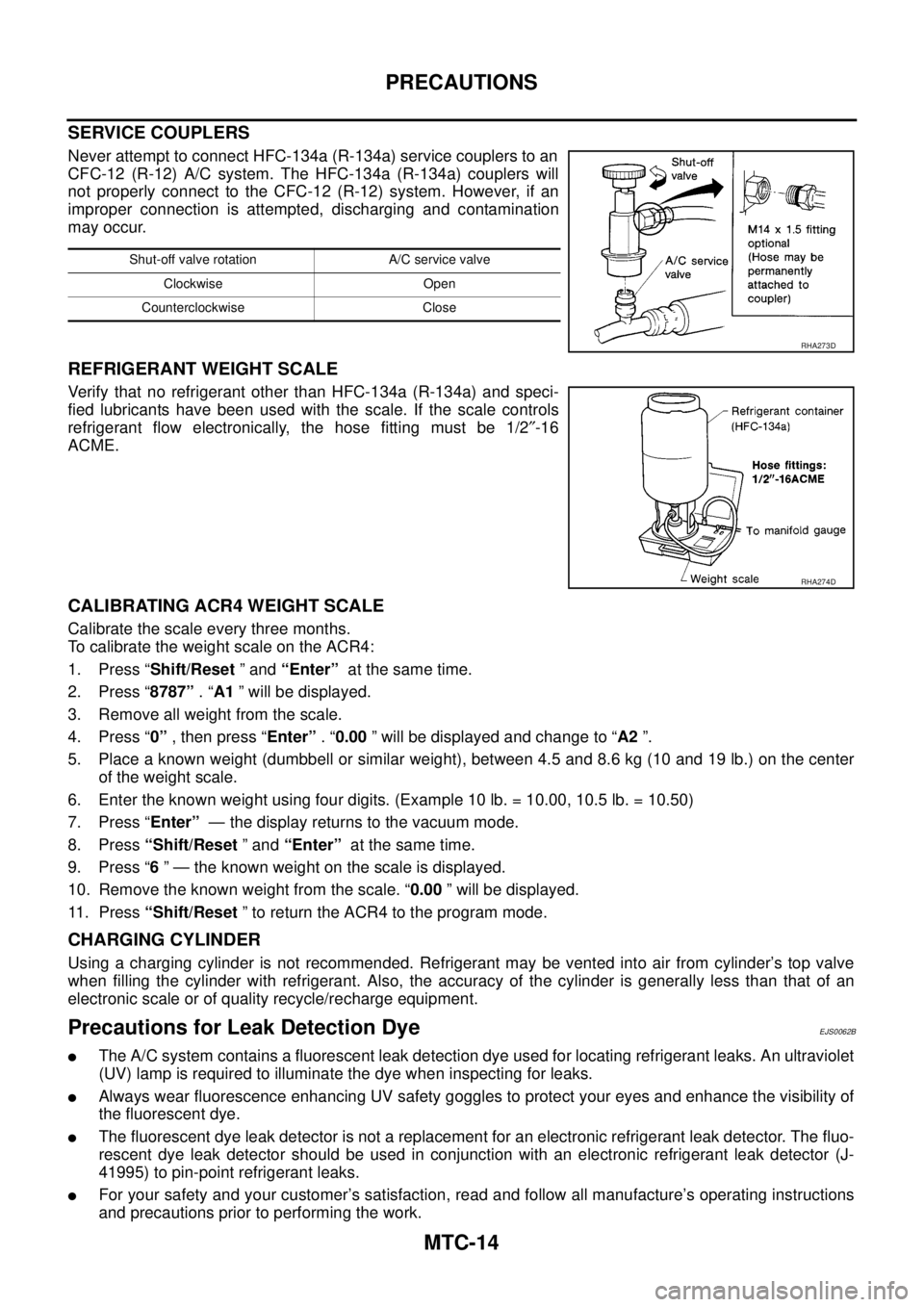
Never attempt to connect HFC-134a (R-134a) service couplers to an
CFC-12 (R-12) A/C system. The HFC-134a (R-134a) couplers will
not properly connect to the CFC-12 (R-12) system. However, if an
improper connection is attempted, discharging and contamination
may occur.
REFRIGERANT WEIGHT SCALE
Verify that no refrigerant other than HFC-134a (R-134a) and speci-
fied lubricants have been used with the scale. If the scale controls
refrigerant flow electronically, the hose fitting must be 1/2²-16
ACME.
CALIBRATING ACR4 WEIGHT SCALE
Calibrate the scale every three months.
To calibrate the weight scale on the ACR4:
1. Press “Shift/Reset”and“Enter”at the same time.
2. Press “8787”.“A1” will be displayed.
3. Remove all weight from the scale.
4. Press “0”, then press “Enter”.“0.00” will be displayed and change to “A2”.
5. Place a known weight (dumbbell or similar weight), between 4.5 and 8.6 kg (10 and 19 lb.) on the center
of the weight scale.
6. Enter the known weight using four digits. (Example 10 lb. = 10.00, 10.5 lb. = 10.50)
7. Press “Enter”— the display returns to the vacuum mode.
8. Press“Shift/Reset”and“Enter”at the same time.
9. Press “6” — the known weight on the scale is displayed.
10. Remove the known weight from the scale. “0.00” will be displayed.
11. Press“Shift/Reset” to return the ACR4 to the program mode.
CHARGING CYLINDER
Using a charging cylinder is not recommended. Refrigerant may be vented into air from cylinder’s top valve
when filling the cylinder with refrigerant. Also, the accuracy of the cylinder is generally less than that of an
electronic scale or of quality recycle/recharge equipment.
Precautions for Leak Detection DyeEJS0062B
lThe A/C system contains a fluorescent leak detection dye used for locating refrigerant leaks. An ultraviolet
(UV) lamp is required to illuminate the dye when inspecting for leaks.
lAlways wear fluorescence enhancing UV safety goggles to protect your eyes and enhance the visibility of
the fluorescent dye.
lThe fluorescent dye leak detector is not a replacement for an electronic refrigerant leak detector. The fluo-
rescent dye leak detector should be used in conjunction with an electronic refrigerant leak detector (J-
41995) to pin-point refrigerant leaks.
lFor your safety and your customer’s satisfaction, read and follow all manufacture’s operating instructions
and precautions prior to performing the work.
Shut-off valve rotation A/C service valve
Clockwise Open
Counterclockwise Close
RHA273D
RHA274D
Page 2678 of 3171

RF-1
ROOF
IBODY
CONTENTS
C
D
E
F
G
H
J
K
L
M
SECTIONRF
A
B
RF
ROOF
PRECAUTIONS .......................................................... 2
Precautions for Supplemental Restraint System
(SRS)“AIRBAG”and“SEATBELTPRE-TEN-
SIONER” .................................................................. 2
Precautions .............................................................. 2
PREPARATION ........................................................... 3
Commercial Service Tool ......................................... 3
SQUEAK AND RATTLE TROUBLE DIAGNOSES..... 4
Work Flow ................................................................ 4
CUSTOMER INTERVIEW ..................................... 4
DUPLICATE THE NOISE AND TEST DRIVE ....... 5
CHECK RELATED SERVICE BULLETINS ........... 5
LOCATE THE NOISE AND IDENTIFY THE
ROOT CAUSE ...................................................... 5
REPAIR THE CAUSE ........................................... 5
CONFIRM THE REPAIR ....................................... 6
Generic Squeak and Rattle Troubleshooting ........... 6
INSTRUMENT PANEL .......................................... 6
CENTER CONSOLE ............................................. 6
DOORS ................................................................. 6
TRUNK .................................................................. 7
SUNROOF/HEADLINING ..................................... 7
SEATS ................................................................... 7
UNDERHOOD ....................................................... 7
Diagnostic Worksheet .............................................. 8
SUNROOF ................................................................ 10
Component Parts and Harness Connector Location... 10
System Description ................................................. 11
TILT UP / SLIDE CLOSE OPERATION ................ 11
TILT DOWN / SLIDE OPEN OPERATION ........... 11AUTO OPERATION ............................................. 11
ANTI-PINCH FUNCTION .................................... 11
MEMORY RESET PROCEDURE ....................... 12
INITIALIZATION PROCEDURE .......................... 12
CAN Communication System Description .............. 13
CAN Communication Unit ....................................... 13
Wiring Diagram — SROOF — ................................ 14
Terminals and Reference Value for BCM ............... 15
Terminals and Reference Value for Sunroof Motor
Assembly ................................................................ 15
Work Flow ............................................................... 16
Trouble Diagnosis Symptom Chart ......................... 16
BCM Power Supply and Ground Circuit Check ...... 16
Sunroof Motor Assembly Power Supply and Ground
Circuit Check .......................................................... 17
Sunroof Switch System Check ............................... 18
Fitting Adjustment ................................................... 20
GAP ADJUSTMENT ............................................ 20
HEIGHT DIFFERENCE ADJUSTMENT .............. 20
Removal and Installation ........................................ 21
SUNROOF UNIT ................................................. 22
GLASS LID .......................................................... 22
WIND DEFLECTOR ............................................ 23
SUNSHADE ........................................................ 23
SUNROOF MOTOR ............................................ 23
DRAIN HOSES .................................................... 25
WEATHERSTRIP ................................................ 25
REAR DRAIN ASSEMBLY .................................. 25
LINK AND WIRE ASSEMBLY ............................. 26