2005 NISSAN NAVARA dimensions
[x] Cancel search: dimensionsPage 322 of 3171
AT-314
ASSEMBLY
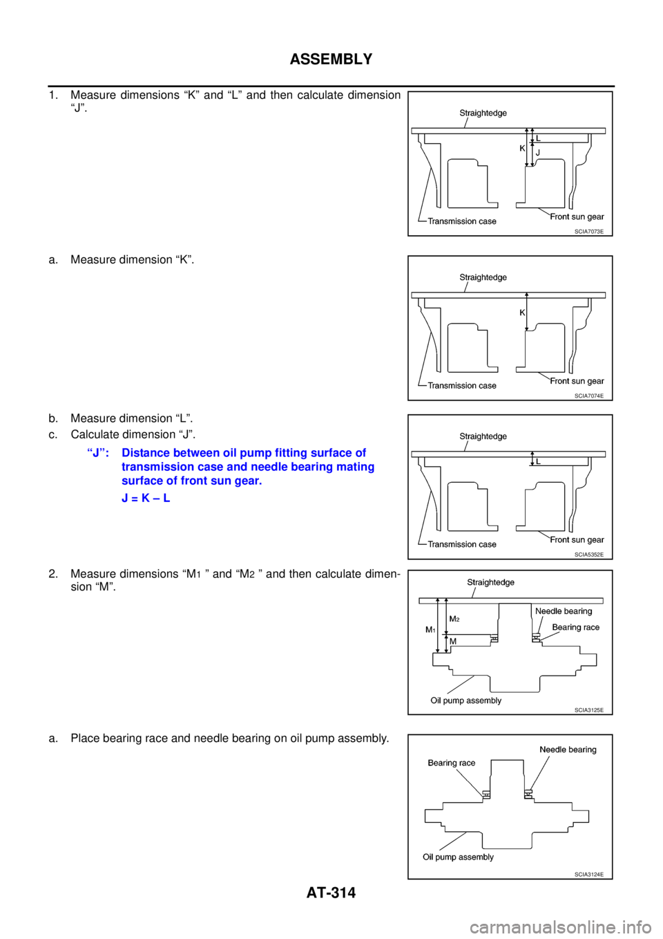
1. Measure dimensions “K” and “L” and then calculate dimension
“J”.
a. Measure dimension “K”.
b. Measure dimension “L”.
c. Calculate dimension “J”.
2. Measure dimensions “M
1”and“M2” and then calculate dimen-
sion “M”.
a. Place bearing race and needle bearing on oil pump assembly.
SCIA7073E
SCIA7074E
“J”: Distance between oil pump fitting surface of
transmission case and needle bearing mating
surface of front sun gear.
J=K–L
SCIA5352E
SCIA3125E
SCIA3124E
Page 495 of 3171

SYSTEM DESCRIPTION
AV-7
C
D
E
F
G
H
I
J
L
MA
B
AV
GPS (Global Positioning System)
GPS (Global Positioning System) was developed for and is con-
trolled by the US Department of Defense. The system utilizes GPS
satellites (NAVSTAR), sending out radio waves while flying on an
orbit around the earth at an altitude of approximately 21,000 km
(13,000 miles).
The GPS receiver calculates the vehicle's position in three dimen-
sions (latitude/longitude/altitude) according to the time lag of the
radio waves received from four or more GPS satellites (three-dimen-
sional positioning). If radio waves were received only from three
GPS satellites, the GPS receiver calculates the vehicle's position in
two dimensions (latitude/longitude), utilizing the altitude data calcu-
lated previously with radio waves from four or more GPS satellites
(two-dimensional positioning).
Position correction by GPS is not available while the vehicle is stopped.
Accuracy of GPS will deteriorate under the following conditions:
lIn two-dimensional positioning, GPS accuracy will deteriorate when altitude of the vehicle position
changes.
lThe accuracy can be even lower depending on the arrangement of the GPS satellites utilized for the posi-
tioning.
lPosition detection is not possible when vehicle is in an area where radio waves from the GPS satellite do
not reach, such as in a tunnel, parking lot in a building, and under an elevated highway. Radio waves from
the GPS satellites may not be received when some object is located over the GPS antenna.
NOTE:
lEven a high-precision three dimensional positioning, the detection result has an error about 10 m (33 ft).
lBecause the signals of GPS satellite is controlled by the Tracking and Control Center in the United States,
the accuracy may be degraded lower intentionally or the radio waves may stop.
Traffic Information (RDS-TMC)
NOTE:This system is built-in NAVI control unit.
The Traffic Information broadcast allows to you to avoid delays due to traffic incidents.
Traffic jams, roadwork, closed roads around your current location, etc. are represented graphically on the map
by icons depicting the nature of the event.
Incidents on the route are automatically brought to your attention when they are approached.
The Traffic Information feature gives you the opportunity to forecast traffic incidents, determine how serious
they are and, via the guidance mode, allows you to detour around traffic incidents.
The navigation system receives traffic information from best available sources and enables the RDS-TMC
(Radio Data System-Traffic Information Channel) to inform and guide you.
The RDS-TMC broadcast is fed by a dedicated FM tuner so that you can still tune your radio station while Traf-
fic Information is being broadcasted.
HANDS-FREE PHONE
lNAVI control unit has Bluetooth module. It can perform wireless hands-free telephone calls using a cellu-
lar phone in vehicle compartment.
l5 or more portable phones can be registered into the NAVI control unit.
SEL526V
Page 775 of 3171
BODY REPAIR
BL-191
C
D
E
F
G
H
J
K
L
MA
B
BL
BODY REPAIRPFP:60100
Body AlignmentEIS00DGG
DESCRIPTION
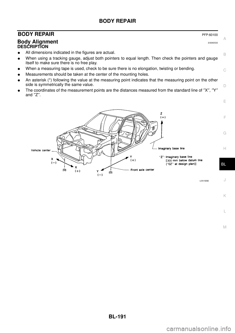
lAll dimensions indicated in the figures are actual.
lWhen using a tracking gauge, adjust both pointers to equal length. Then check the pointers and gauge
itself to make sure there is no free play.
lWhen a measuring tape is used, check to be sure there is no elongation, twisting or bending.
lMeasurements should be taken at the center of the mounting holes.
lAn asterisk (*) following the value at the measuring point indicates that the measuring point on the other
side is symmetrically the same value.
lThe coordinates of the measurement points are the distances measured from the standard line of²X²,²Y²
and²Z².
LIIA1506E
Page 1387 of 3171
PRECAUTIONS
EM-5
C
D
E
F
G
H
I
J
K
L
MA
EM
Precautions For Liquid GasketEBS01E5N
REMOVAL OF LIQUID GASKET
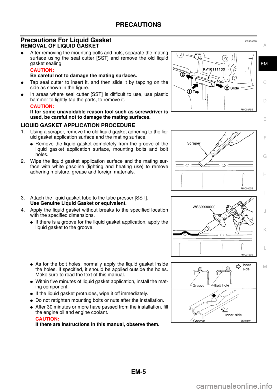
lAfter removing the mounting bolts and nuts, separate the mating
surface using the seal cutter [SST] and remove the old liquid
gasket sealing.
CAUTION:
Be careful not to damage the mating surfaces.
lTap seal cutter to insert it, and then slide it by tapping on the
side as shown in the figure.
lIn areas where seal cutter [SST] is difficult to use, use plastic
hammer to lightly tap the parts, to remove it.
CAUTION:
If for some unavoidable reason tool such as screwdriver is
used, be careful not to damage the mating surfaces.
LIQUID GASKET APPLICATION PROCEDURE
1. Using a scraper, remove the old liquid gasket adhering to the liq-
uid gasket application surface and the mating surface.
lRemove the liquid gasket completely from the groove of the
liquid gasket application surface, mounting bolts and bolt
holes.
2. Wipe the liquid gasket application surface and the mating sur-
face with white gasoline (lighting and heating use) to remove
adhering moisture, grease and foreign materials.
3. Attach the liquid gasket tube to the tube presser [SST].
Use Genuine Liquid Gasket or equivalent.
4. Apply the liquid gasket without breaks to the specified location
with the specified dimensions.
lIf there is a groove for the liquid gasket application, apply the
liquid gasket to the groove.
lAs for the bolt holes, normally apply the liquid gasket inside
the holes. If specified, it should be applied outside the holes.
Make sure to read the text of this manual.
lWithin five minutes of liquid gasket application, install the mat-
ing component.
lIf the liquid gasket protrudes, wipe it off immediately.
lDo not retighten mounting bolts or nuts after the installation.
lAfter 30 minutes or more have passed from the installation, fill
the engine oil and engine coolant.
CAUTION:
If there are instructions in this manual, observe them.
PBIC0275E
PBIC0003E
PBIC2160E
SEM159F
Page 1390 of 3171
EM-8
PREPARATION
Commercial Service Tools
EBS01E5P
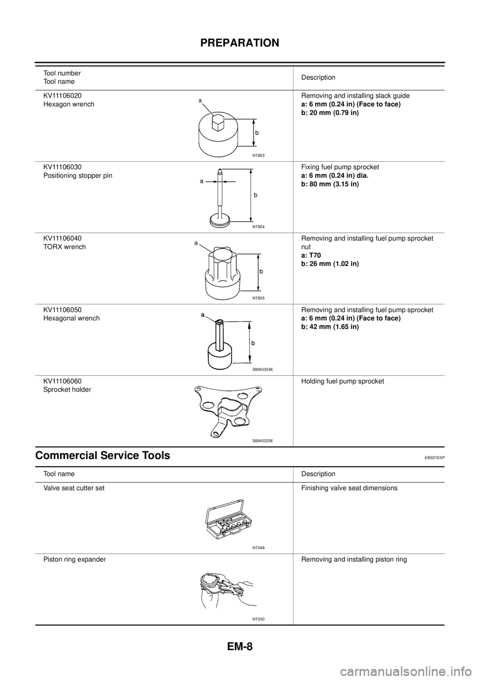
KV11106020
Hexagon wrenchRemoving and installing slack guide
a: 6 mm (0.24 in) (Face to face)
b: 20 mm (0.79 in)
KV11106030
Positioning stopper pinFixing fuel pump sprocket
a: 6 mm (0.24 in) dia.
b: 80 mm (3.15 in)
KV11106040
TORX wrenchRemoving and installing fuel pump sprocket
nut
a: T70
b: 26 mm (1.02 in)
KV11106050
Hexagonal wrenchRemoving and installing fuel pump sprocket
a: 6 mm (0.24 in) (Face to face)
b: 42 mm (1.65 in)
KV11106060
Sprocket holderHolding fuel pump sprocket Tool number
Tool nameDescription
NT803
NT804
NT805
SBIA0224E
SBIA0225E
Tool nameDescription
Valve seat cutter set Finishing valve seat dimensions
Piston ring expander Removing and installing piston ring
NT048
NT030
Page 1421 of 3171
OIL PAN AND OIL STRAINER
EM-39
C
D
E
F
G
H
I
J
K
L
MA
EM
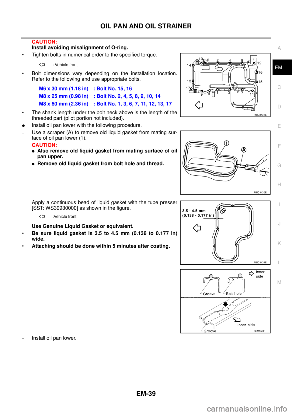
CAUTION:
Install avoiding misalignment of O-ring.
• Tighten bolts in numerical order to the specified torque.
• Bolt dimensions vary depending on the installation location.
Refer to the following and use appropriate bolts.
• The shank length under the bolt neck above is the length of the
threaded part (pilot portion not included).
lInstall oil pan lower with the following procedure.
–Use a scraper (A) to remove old liquid gasket from mating sur-
face of oil pan lower (1).
CAUTION:
lAlso remove old liquid gasket from mating surface of oil
pan upper.
lRemove old liquid gasket from bolt hole and thread.
–Apply a continuous bead of liquid gasket with the tube presser
[SST: WS39930000] as shown in the figure.
Use Genuine Liquid Gasket or equivalent.
•Be sure liquid gasket is 3.5 to 4.5 mm (0.138 to 0.177 in)
wide.
•Attaching should be done within 5 minutes after coating.
–Install oil pan lower.
: Vehicle front
M6x30mm(1.18in) :BoltNo.15,16
M8 x 25 mm (0.98 in) : Bolt No. 2, 4, 5, 8, 9, 10, 14
M8 x 60 mm (2.36 in) : Bolt No. 1, 3, 6, 7, 11, 12, 13, 17
PBIC3431E
PBIC3430E
:Vehicle front
PBIC3434E
SEM159F
Page 1467 of 3171
PRIMARY TIMING CHAIN
EM-85
C
D
E
F
G
H
I
J
K
L
MA
EM
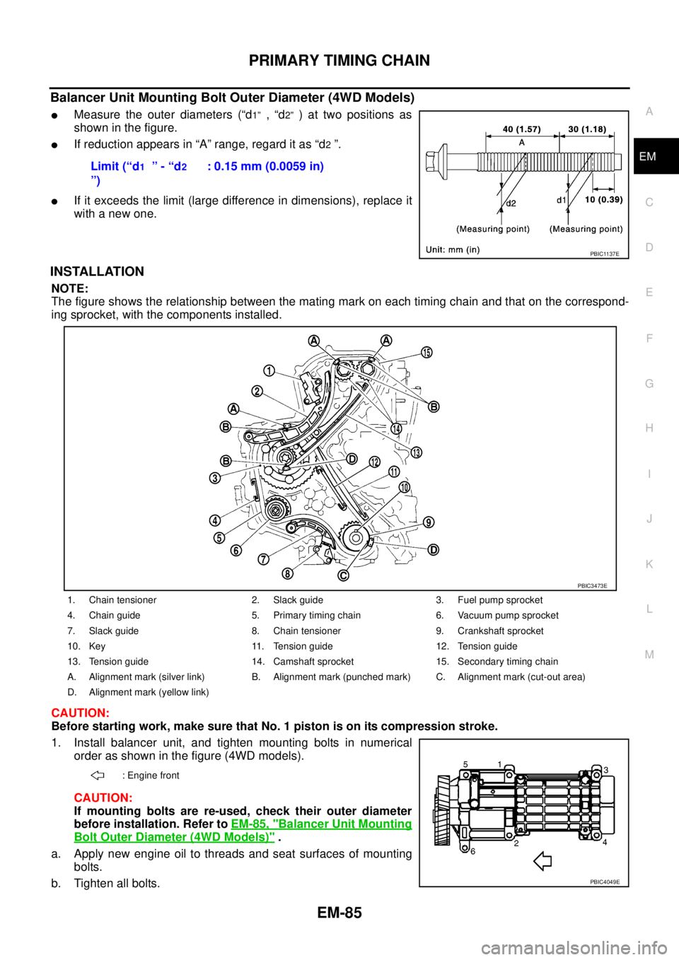
Balancer Unit Mounting Bolt Outer Diameter (4WD Models)
lMeasure the outer diameters (“d1”,“d2”)attwopositionsas
showninthefigure.
lIf reduction appears in “A” range, regard it as “d2”.
lIf it exceeds the limit (large difference in dimensions), replace it
with a new one.
INSTALLATION
NOTE:
The figure shows the relationship between the mating mark on each timing chain and that on the correspond-
ing sprocket, with the components installed.
CAUTION:
Before starting work, make sure that No. 1 piston is on its compression stroke.
1. Install balancer unit, and tighten mounting bolts in numerical
order as shown in the figure (4WD models).
CAUTION:
If mounting bolts are re-used, check their outer diameter
before installation. Refer toEM-85, "
Balancer Unit Mounting
Bolt Outer Diameter (4WD Models)".
a. Apply new engine oil to threads and seat surfaces of mounting
bolts.
b. Tighten all bolts.Limit (“d
1”-“d2
”): 0.15 mm (0.0059 in)
PBIC1137E
1. Chain tensioner 2. Slack guide 3. Fuel pump sprocket
4. Chain guide 5. Primary timing chain 6. Vacuum pump sprocket
7. Slack guide 8. Chain tensioner 9. Crankshaft sprocket
10. Key 11. Tension guide 12. Tension guide
13. Tension guide 14. Camshaft sprocket 15. Secondary timing chain
A. Alignment mark (silver link) B. Alignment mark (punched mark) C. Alignment mark (cut-out area)
D. Alignment mark (yellow link)
: Engine front
PBIC3473E
PBIC4049E
Page 1483 of 3171
![NISSAN NAVARA 2005 Repair Workshop Manual CYLINDER HEAD
EM-101
C
D
E
F
G
H
I
J
K
L
MA
EM
8. Using the valve spring compressor [SST], compress valve
springs.
Then install valve collets using magnet hand.
lAfter installing valve collets, tap th NISSAN NAVARA 2005 Repair Workshop Manual CYLINDER HEAD
EM-101
C
D
E
F
G
H
I
J
K
L
MA
EM
8. Using the valve spring compressor [SST], compress valve
springs.
Then install valve collets using magnet hand.
lAfter installing valve collets, tap th](/manual-img/5/57362/w960_57362-1482.png)
CYLINDER HEAD
EM-101
C
D
E
F
G
H
I
J
K
L
MA
EM
8. Using the valve spring compressor [SST], compress valve
springs.
Then install valve collets using magnet hand.
lAfter installing valve collets, tap the stem end using the plastic
hammer, and check the installation status.
9. Install valve lifters and adjusting shims to the same positions as before.
INSPECTION AFTER DISASSEMBLY
Valve Dimension
lCheck dimensions of each valve. For dimensions, refer toEM-
136, "Valve Dimensions".
lIf dimensions are out of the standard, replace valve.
Valve Guide Clearance
Valve Stem Diameter
lMeasure diameter of valve stem with micrometer.
Valve Guide Inner Diameter
lMeasure inner diameter of valve guide with inside micrometer.
Valve Guide Clearance
l(Valve guide clearance) = (Valve guide inner diameter) – (Valve stem diameter).
PBIC2388E
SEM188A
Standard
Intake : 5.965 - 5.980 mm (0.2348 - 0.2354 in)
Exhaust : 5.945 - 5.960 mm (0.2341 - 0.2346 in)
SEM938C
Standard
Intake and Exhaust : 6.000 - 6.018 mm (0.2362 - 0.2369 in)
Valve guide clearance:
Standard
Intake : 0.020 - 0.053 mm (0.0008 - 0.0021 in)
Exhaust : 0.040 - 0.073 mm (0.0016 - 0.0029 in)
Limit
Intake : 0.08 mm (0.0031 in)
Exhaust : 0.10 mm (0.0039 in)