2005 NISSAN NAVARA dimensions
[x] Cancel search: dimensionsPage 1486 of 3171
EM-104
CYLINDER HEAD
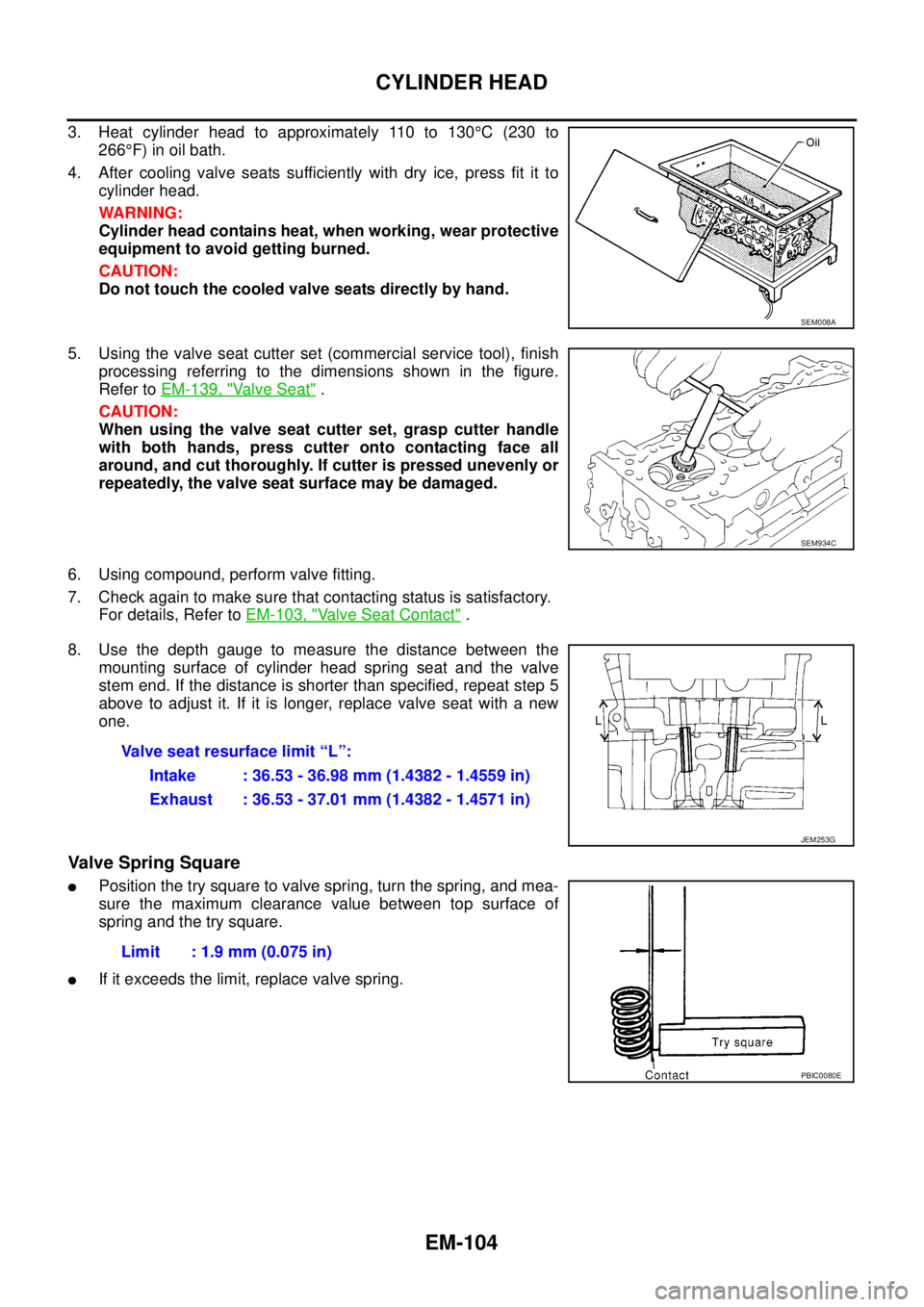
3. Heat cylinder head to approximately 110 to 130°C(230to
266°F) in oil bath.
4. After cooling valve seats sufficiently with dry ice, press fit it to
cylinder head.
WARNING:
Cylinder head contains heat, when working, wear protective
equipment to avoid getting burned.
CAUTION:
Do not touch the cooled valve seats directly by hand.
5. Using the valve seat cutter set (commercial service tool), finish
processing referring to the dimensions shown in the figure.
Refer toEM-139, "
Va l v e S e a t".
CAUTION:
When using the valve seat cutter set, grasp cutter handle
with both hands, press cutter onto contacting face all
around, and cut thoroughly. If cutter is pressed unevenly or
repeatedly, the valve seat surface may be damaged.
6. Using compound, perform valve fitting.
7. Check again to make sure that contacting status is satisfactory.
For details, Refer toEM-103, "
Valve Seat Contact".
8. Use the depth gauge to measure the distance between the
mounting surface of cylinder head spring seat and the valve
stem end. If the distance is shorter than specified, repeat step 5
above to adjust it. If it is longer, replace valve seat with a new
one.
Valve Spring Square
lPosition the try square to valve spring, turn the spring, and mea-
sure the maximum clearance value between top surface of
spring and the try square.
lIf it exceeds the limit, replace valve spring.
SEM008A
SEM934C
Valve seat resurface limit “L”:
Intake : 36.53 - 36.98 mm (1.4382 - 1.4559 in)
Exhaust : 36.53 - 37.01 mm (1.4382 - 1.4571 in)
JEM253G
Limit : 1.9 mm (0.075 in)
PBIC0080E
Page 1487 of 3171
CYLINDER HEAD
EM-105
C
D
E
F
G
H
I
J
K
L
MA
EM
Valve Spring Dimensions and Valve Spring Pressure Load
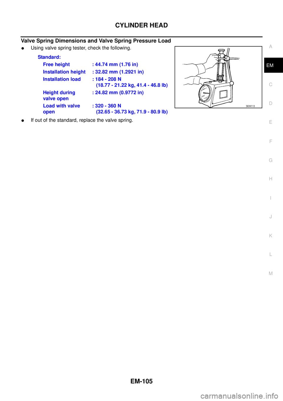
lUsing valve spring tester, check the following.
lIf out of the standard, replace the valve spring.Standard:
Free height : 44.74 mm (1.76 in)
Installation height : 32.82 mm (1.2921 in)
Installation load : 184 - 208 N
(18.77 - 21.22 kg, 41.4 - 46.8 lb)
Height during
valve open: 24.82 mm (0.9772 in)
Load with valve
open:320-360N
(32.65 - 36.73 kg, 71.9 - 80.9 lb)
SEM113
Page 1512 of 3171
EM-130
CYLINDER BLOCK
2. Install main bearing caps and tighten bolts to the specified torque. Refer toEM-114, "ASSEMBLY".This
will prevent distortion of cylinder bores.
3. Cut cylinder bore.
NOTE:
lWhen any cylinder needs boring, all other cylinders must also be bored.
lDo not cut too much out of cylinder bore at a time. Cut only 0.05 mm (0.0020 in) or so at a time.
4. Hone cylinders to obtain the specified piston-to-cylinder bore clearance.
5. Measure finished cylinder bore for the out-of-round and taper.
NOTE:
lMeasurement should be done after cylinder bore cools down.
CRANKSHAFT MAIN JOURNAL DIAMETER
lUse micrometer to measure crankshaft main journal diameter.
lIf out of the standard, measure the main bearing oil clearance.
then use the undersize bearing. Refer toEM-132, "
MAIN BEAR-
ING OIL CLEARANCE".
CRANKSHAFT PIN JOURNAL DIAMETER
lUse micrometer to measure crankshaft pin journal diameter.
lIf out of the standard, measure the connecting rod bearing oil
clearance. then use the undersize bearing. Refer toEM-131,
"CONNECTING ROD BEARING OIL CLEARANCE".
CRANKSHAFT OUT-OF-ROUND AND TAPER
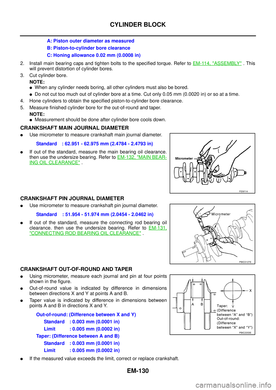
lUsing micrometer, measure each journal and pin at four points
showninthefigure.
lOut-of-round value is indicated by difference in dimensions
between directions X and Y at points A and B.
lTaper value is indicated by difference in dimensions between
points A and B in directions X and Y.
lIf the measured value exceeds the limit, correct or replace crankshaft.A: Piston outer diameter as measured
B: Piston-to-cylinder bore clearance
C: Honing allowance 0.02 mm (0.0008 in)
Standard : 62.951 - 62.975 mm (2.4784 - 2.4793 in)
FEM114
Standard : 51.954 - 51.974 mm (2.0454 - 2.0462 in)
PBIC0127E
Out-of-round: (Difference between X and Y)
Standard : 0.003 mm (0.0001 in)
Limit : 0.005 mm (0.0002 in)
Taper: (Difference between A and B)
Standard : 0.003 mm (0.0001 in)
Limit : 0.005 mm (0.0002 in)
PBIC2203E
Page 1516 of 3171
EM-134
CYLINDER BLOCK
FLYWHEEL DEFLECTION
lMeasure the deflection of flywheel contact surface to clutch with
a dial indicator.
lMeasure the deflection at 210 mm (8.27 in) dia.
lIf measured value is out of the standard, replace flywheel.
CAUTION:
When measuring, keep magnetic fields (such as dial indicator
stand) away from signal plate of the rear end of crankshaft.
MOVEMENT AMOUNT OF FLYWHEEL
CAUTION:
Do not disassemble double mass flywheel.
Movement Amount of Thrust (Fore-and-Aft) Direction
lMeasure the movement amount of thrust (fore-and-aft) direction when 100 N (10.2 kg, 22 lb) force is
added at the portion of 125 mm (4.92 in) radius from the center of flywheel.
lIf measured value is out of the standard, replace flywheel.
Movement Amount in Radial (Rotation) Direction
Check the movement amount of radial (rotation) direction with the following procedure:
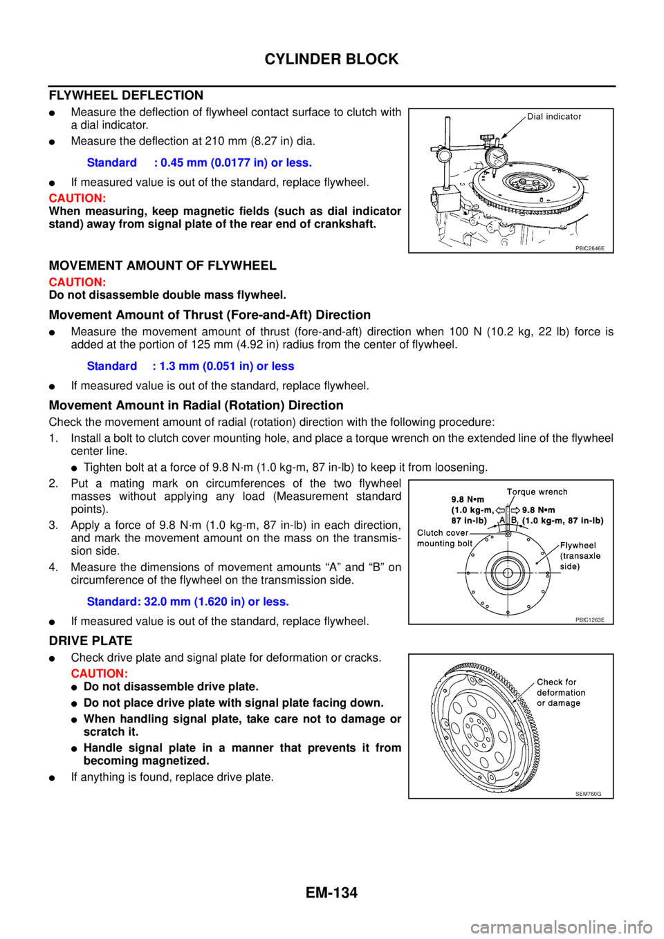
1. Install a bolt to clutch cover mounting hole, and place a torque wrench on the extended line of the flywheel
center line.
lTighten bolt at a force of 9.8 N·m (1.0 kg-m, 87 in-lb) to keep it from loosening.
2. Put a mating mark on circumferences of the two flywheel
masses without applying any load (Measurement standard
points).
3. Apply a force of 9.8 N·m (1.0 kg-m, 87 in-lb) in each direction,
and mark the movement amount on the mass on the transmis-
sion side.
4. Measure the dimensions of movement amounts “A” and “B” on
circumference of the flywheel on the transmission side.
lIf measured value is out of the standard, replace flywheel.
DRIVE PLATE
lCheck drive plate and signal plate for deformation or cracks.
CAUTION:
lDo not disassemble drive plate.
lDo not place drive plate with signal plate facing down.
lWhen handling signal plate, take care not to damage or
scratch it.
lHandle signal plate in a manner that prevents it from
becoming magnetized.
lIf anything is found, replace drive plate.Standard : 0.45 mm (0.0177 in) or less.
PBIC2646E
Standard : 1.3 mm (0.051 in) or less
Standard: 32.0 mm (1.620 in) or less.
PBIC1263E
SEM760G
Page 1518 of 3171

EM-136
SERVICE DATA AND SPECIFICATIONS (SDS)
CYLINDER HEAD
Unit: mm (in)
VA LV E
Valve Dimensions
Unit: mm (in)
Valve Clearance
Unit: mm (in)
*: Approximately 80°C (176°F) Item Standard Limit
Cylinder head distortion Less than 0.04 (0.0016) 0.1 (0.004)
JEM204G
Valve head diameter “D”Intake 28.0 - 28.3 (1.102 - 1.114)
Exhaust 26.0 - 26.3 (1.024 - 1.035)
Valve length “L”Intake 106.72 (4.2016)
Exhaust 106.36 (4.1874)
Valve stem diameter “d”Intake 5.965 - 5.980 (0.2348 - 0.2354)
Exhaust 5.945 - 5.960 (0.2341 - 0.2346)
Valve seat angle “a” Intake and exhaust 45 degrees 15¢- 45 degrees 45¢
Valvemargin“T”Intake 1.60 (0.0630)
Exhaust2WD models 1.80 (0.0709)
4WD models 1.48 (0.0583)
Valvemargin“T”limitMore than 1.0 (0.039)
Valve stem end surface grinding limit Less than 0.2 (0.008)
SEM188
Item Cold Hot* (Reference data)
Intake 0.24 - 0.32 (0.0094 - 0.0126) 0.274 - 0.386 (0.0108 - 0.0152)
Exhaust 0.26 - 0.34 (0.0102 - 0.0134) 0.308 - 0.432 (0.0121 - 0.0170)
Page 1624 of 3171

GI-2
TIGHTENING TORQUE OF STANDARD BOLTS .... 55
Tightening Torque Table ......................................... 55
IDENTIFICATION INFORMATION ............................ 56
Model Variation ....................................................... 56
Identification Number .............................................. 57
VEHICLE IDENTIFICATION NUMBER
ARRANGEMENT ................................................. 57
IDENTIFICATION PLATE .................................... 58
ENGINE SERIAL NUMBER ................................ 58TRANSFER SERIAL NUMBER ........................... 58
AUTOMATIC TRANSMISSION NUMBER ........... 58
MANUAL TRANSMISSION NUMBER ................. 59
Dimensions ............................................................. 60
KING CAB ............................................................ 60
DOUBLE CAB ...................................................... 60
Wheels & Tyres ....................................................... 60
TERMINOLOGY ........................................................ 61
ISO 15031-2 Terminology List ................................. 61
Page 1682 of 3171

GI-60
IDENTIFICATION INFORMATION
Dimensions
EAS001DO
KING CAB
Unit: mm (in)
DOUBLE CAB
Unit: mm (in)
Wheels & TyresEAS001DP
Drive Type 2WD 4WD
Tyre size 235/70R16 255/70R16 235/70R16 255/70R16 265/70R16 255/65R17
Overall length 5220 (205.5)
Overall width 1850 (72.8)
Overall height 1743 (68.6) 1756 (69.1) 1751 (68.9) 1766 (69.5) 1777 (70.0) 1771 (69.7)
Front tread width
1570 (61.8)
Rear tread width
Wheelbase 3200 (126.0)
Drive Type 2WD 4WD
Tyre size 255/70R16 255/65R17 235/70R16 255/70R16 265/70R16 255/65R17
Overall length 5220 (205.5)
Overall width 1850 (72.8)
Overall height
(with Roof Rack)1881 (74.1) 1885 (74.2) 1873 (73.7) 1888 (74.3) 1899 (74.8) 1893 (74.5)
Overall height
(without Roof Rack)1771 (69.7) 1775 (69.9) 1764 (69.4) 1779 (70.0) 1789 (70.4) 1784 (70.2)
Front tread width
1570 (61.8)
Rear tread width
Wheelbase 3200 (126.0)
Drive Type Road wheel Tyre Spare tyre size
All16 X 7J Steel 235/70R16 235/70R16
16 X 7J Aluminum Alloy235/70R16 235/70R16
255/70R16 255/70R16
17 X 7J Aluminum Alloy 255/65R17 255/65R17
Page 1755 of 3171
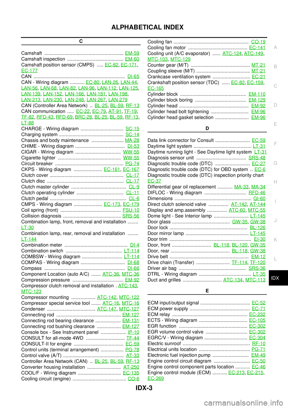
IDX-3
A
C
D
E
F
G
H
I
J
K
L B
IDX
ALPHABETICAL INDEX
C
Camshaft ...........................................................EM-59
Camshaft inspection ..........................................EM-60
Camshaft position sensor (CMPS) .....EC-82,EC-171,
EC-177
CAN ....................................................................DI-65
CAN - Wiring diagram ...........EC-80,LAN-26,LAN-44,
LAN-56
,LAN-68,LAN-82,LAN-96,LAN-112,LAN-125,
LAN-139
,LAN-152,LAN-166,LAN-181,LAN-198,
LAN-213
,LAN-230,LAN-248,LAN-267,LAN-279
CAN (Controller Area Network) ..BL-25,BL-59,RF-13
CAN communication .....EC-22,EC-79,AT-91,TF-19,
TF-82
,RFD-43,RFD-69,BRC-28,BL-25,BL-59,RF-13,
LT-88
CHARGE - Wiring diagram ................................SC-15
Charging system ................................................SC-14
Chassis and body maintenance ........................MA-28
CHIME - Wiring diagram .....................................DI-53
CIGAR - Wiring diagram ..................................WW-55
Cigarette lighter ...............................................WW-55
Circuit breaker ...................................................PG-74
CKPS - Wiring diagram .....................EC-161,EC-167
Clutch cover .......................................................CL-17
Clutch disc .........................................................CL-17
Clutch master cylinder .........................................CL-9
Clutch operating cylinder ...................................CL-11
Clutch pedal .........................................................CL-6
CMPS - Wiring diagram .....................EC-173,EC-179
Coil spring (front) .............................................FSU-10
Collision diagnosis ...........................................SRS-56
Combination lamp, front, removal and installation ........
LT-30
Combination lamp, rear, removal and installation ........
LT-144
Combination meter ...............................................DI-4
Combination switch ..........................................LT-114
COMBSW - Wiring diagram ..............................LT-114
COMPAS - Wiring diagram .................................DI-68
Compass ............................................................DI-66
Component Location (auto A/C) .......ATC-36,MTC-36
Compression pressure ......................................EM-92
Compressor clutch removal and installation .ATC-143,
MTC-123
Compressor mounting ..................ATC-142,MTC-122
Compressor special service tool .......ATC-16,MTC-16
Condenser ....................................ATC-147,MTC-127
Connecting rod ................................................EM-127
Connecting rod bearing clearance ...................EM-131
Connecting rod bushing clearance ..................EM-127
Console box - See Instrument panel ...................IP-10
CONSULT for all-mode 4WD .............................TF-44
CONSULT-II for engine .....................................EC-59
Control units (terminal arrangement) .................PG-78
Control valve (A/T) .............................................AT-33
Controller Area Network (CAN) ..BL-25,BL-59,RF-13
Converter housing installation .........................AT-250
COOL/F - Wiring diagram ................................EC-135
Cooling circuit (engine) ........................................CO-6
Cooling fan ........................................................CO-19
Cooling fan motor ............................................EC-141
Cooling unit (A/C evaporator) ......ATC-124,ATC-149,
MTC-103
,MTC-129
Counter gear (M/T) ............................................MT-21
Coupling sleeve (M/T) ........................................MT-21
Crankcase ventilation system ............................EC-21
Crankshaft position sensor (TDC) ......EC-82,EC-159,
EC-165
Cylinder block .................................................EM-110
Cylinder block boring ......................................EM-129
Cylinder head ....................................................EM-92
Cylinder head bolt tightening ............................EM-96
Cylinder head gasket selection .........................EM-96
D
Data link connector for Consult ..........................EC-59
Daytime light system ...........................................LT-31
Daytime running light - See Daytime light systemLT-31
Diagnosis sensor unit .....................................SRS-48
Diagnostic trouble code (DTC) ..........................EC-27
Diagnostic trouble code (DTC) for OBD system ..EC-6
Diagnostic trouble code (DTC) inspection priority chart
EC-37
Differential gear oil replacement ...........MA-33,MA-34
DIFLOC - Wiring diagram ...............................RFD-46
Dimensions .........................................................GI-60
Direct clutch solenoid valve ...............AT-142,AT-144
Display and amp.assembly ...............ATC-60,MTC-55
Dome light - See Interior lamp ..........................LT-145
Door glass ...........................................GW-35,GW-38
Door lock ..........................................................BL-126
Door mirror lamp ...............................................LT-145
Door trim .............................................................EI-30
Door, front .............................BL-118,BL-120,GW-35
Door, rear ............................................BL-118,GW-38
Drive belt ...........................................................EM-12
Drive chain (Transfer) .........................TF-114,TF-120
Driver air bag ..................................................SRS-36
DTRL - Wiring diagram .......................................LT-35
Duct and grilles .............................ATC-134,MTC-113
E
ECM input/output signal .....................................EC-52
ECM power supply .............................................EC-71
ECM relay ........................................................EC-232
ECTS - Wiring diagram ....................................EC-105
EGR function ...................................................EC-302
EGR volume control valve ...............................EC-302
EGRC/V - Wiring diagram ................................EC-304
Electric sunroof ..................................................RF-10
Electrical units location ......................................PG-71
Electronic fuel injection pump ...........................EM-49
Engine control circuit diagram ...........................EC-50
Engine control component parts location ...........EC-46
Engine control module (ECM) ...........EC-213,EC-215,
EC-269