2005 NISSAN NAVARA height adjustment
[x] Cancel search: height adjustmentPage 585 of 3171
BL-1
BODY, LOCK & SECURITY SYSTEM
IBODY
CONTENTS
C
D
E
F
G
H
J
K
L
M
SECTIONBL
A
B
BL
BODY, LOCK & SECURITY SYSTEM
PRECAUTIONS .......................................................... 4
Precautions for Supplemental Restraint System
(SRS)“AIRBAG”and“SEATBELTPRE-TEN-
SIONER” .................................................................. 4
Precautions for procedures with out cowl top cover..... 4
Precautions for Work ................................................ 4
Wiring Diagrams and Trouble Diagnosis .................. 4
PREPARATION ........................................................... 5
Commercial Service Tools ........................................ 5
SQUEAK AND RATTLE TROUBLE DIAGNOSES..... 6
Work Flow ................................................................ 6
CUSTOMER INTERVIEW ..................................... 6
DUPLICATE THE NOISE AND TEST DRIVE ....... 7
CHECK RELATED SERVICE BULLETINS ........... 7
LOCATE THE NOISE AND IDENTIFY THE
ROOT CAUSE ...................................................... 7
REPAIR THE CAUSE ........................................... 7
CONFIRM THE REPAIR ....................................... 8
Generic Squeak and Rattle Troubleshooting ........... 8
INSTRUMENT PANEL .......................................... 8
CENTER CONSOLE ............................................. 8
DOORS ................................................................. 8
TRUNK .................................................................. 9
SUNROOF/HEADLINING ..................................... 9
SEATS ................................................................... 9
UNDERHOOD ....................................................... 9
Diagnostic Worksheet ............................................ 10
HOOD ....................................................................... 12
Fitting Adjustment .................................................. 12
LONGITUDINAL AND LATERAL CLEARANCE
ADJUSTMENT .................................................... 13
FRONT END HEIGHT ADJUSTMENT ............... 13
SURFACE HEIGHT ADJUSTMENT ................... 13
Removal and Installation of Hood Assembly .......... 14
REMOVAL ........................................................... 14
INSTALLATION ................................................... 14
Removal and Installation of Hood Hinge ................ 15
REMOVAL ........................................................... 15
INSTALLATION ................................................... 15
Removal and Installation of Hood Lock Control ..... 15REMOVAL ........................................................... 15
INSTALLATION ................................................... 16
Hood Lock Control Inspection ................................ 17
RADIATOR CORE SUPPORT .................................. 18
Removal and Installation ........................................ 18
REMOVAL ........................................................... 18
INSTALLATION ................................................... 19
FRONT FENDER ...................................................... 20
Removal and Installation ........................................ 20
REMOVAL ........................................................... 20
INSTALLATION ................................................... 20
POWER DOOR LOCK SYSTEM .............................. 21
Component Parts and Harness Connector Location... 21
KING CAB ........................................................... 21
DOUBLE CAB ..................................................... 22
System Description ................................................. 23
OUTLINE ............................................................. 24
CAN Communication System Description .............. 25
CAN Communication Unit ....................................... 25
Schematic ............................................................... 26
Wiring Diagram —D/LOCK— ................................. 27
Terminals and Reference Value for BCM ............... 34
CONSULT-II Function (BCM) ................................. 35
CONSULT-II BASIC OPERATION PROCEDURE
... 35
CONSULT-II APPLICATION ITEMS .................... 36
Work Flow ............................................................... 37
Trouble Diagnoses Chart by Symptom ................... 37
Check Power Supply and Ground Circuit ............... 37
Check Door Switch ................................................. 39
CHECK DOOR SWITCH (DOUBLE CAB) .......... 39
CHECK DOOR SWITCH (KING CAB) ................ 41
Check Key Switch ................................................... 43
Check Door Key Cylinder Switch (LHD Model Only)... 45
Check Front Door Lock Actuator (Driver Side) ....... 48
Check Front Door Lock Actuator (Passenger Side)... 49
Check Front Door Lock Actuator Switch ................. 50
Check Rear Door Lock Actuator LH (Double Cab
Model) ..................................................................... 50
Check Rear Door Lock Actuator RH (Double Cab
Page 597 of 3171

HOOD
BL-13
C
D
E
F
G
H
J
K
L
MA
B
BL
LONGITUDINAL AND LATERAL CLEARANCE ADJUSTMENT
1. Remove the hood lock, loosen the hood hinge nuts and close the hood.
2. Adjust the lateral and longitudinal clearance, and open the hood to tighten the mounting bolts to the spec-
ified torque.
3. Install the hood lock temporarily, and align the hood striker and lock so that the centers of striker and lock
become vertical viewed from the front, by moving the hood lock laterally.
4. Tighten hood lock mounting bolts to the specified torque.
FRONT END HEIGHT ADJUSTMENT
1. Remove the hood lock and adjust the height by rotating the bumper rubber until the hood becomes 1 to1.5
mm (0.04 to 0.059 in) lower than the fender.
2. Temporarily tighten the hood lock, and position it by engaging it with the hood striker. Check the lock and
striker for looseness, and tighten the hood lock mounting bolts to the specified torque.
CAUTION:
Adjust right/left clearance between hood and each part to the following specification.
SURFACE HEIGHT ADJUSTMENT
1. Remove the hood lock, and adjust the surface height difference of hood, fender and headlamp according
to the fitting standard dimension, by rotating RH and LH bumper rubbers.
2. Install hood lock temporarily, and move hood lock laterally until the centers of striker and lock become ver-
tical when viewed from the front.
3. Check that the hood lock secondary latch is properly engaged with the secondary striker with hood's own
weight.
4. Check that the hood lock primary latch is securely engaged with the hood striker with hood's own weight
by dropping hood from approx. 200 mm (7.87) height.
CAUTION:
Do not drop hood from a height of 300 mm (11.81 in) or more.
5. Move hood lockup and down until striker smoothly engages the lock when the hood is closed.
6. When pulling the hood opener lever gently, make sure that front end of the hood rises by approximately 20
mm (0.79) and that hood striker and hood lock primary latch is disengaged. Also make sure that hood
opener returns to the original position.
7. After adjustment, tighten lock bolts to the specified torque.
CAUTION:
lAfter installing, apply touch-up paint (the body color) onto the head of the hinge mounting nuts.
lAdjust evenness between hood and each part to the following specification.
Portion Clearance
Hood - Front grille A - A (a) 3.7 - 8.3 mm (0.146 - 0.327 in)
Hood - Front fender B - B (c) 3.6 - 5.6 mm (0.142 - 0.220 in)
Hood - Headlamp C - C (e) 6.0 - 8.0 mm (0.236 - 0.315 in)
Portion R / L difference
Hood - Front grille A - A (a) Less than 2.2 mm (0.087 in)
Hood - Front fender B - B (c) Less than 1.0 mm (0.039 In)
Portion Surface height
Hood - Front grille A - A (b) -1.7 - 3.1 mm (-0.067 - 0.122 in)
Hood - Front fender B - B (d) -1.0 - 1.0 mm (-0.039 - 0.039 in)
Hood - Headlamp C - C (f) -1.3 - 2.7 mm (-0.051 - 0.106 in)
Page 702 of 3171
BL-118
DOOR
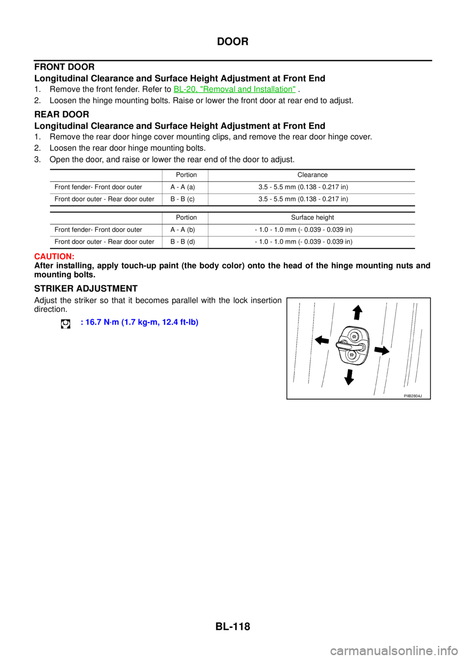
FRONT DOOR
Longitudinal Clearance and Surface Height Adjustment at Front End
1. Remove the front fender. Refer toBL-20, "Removal and Installation".
2. Loosen the hinge mounting bolts. Raise or lower the front door at rear end to adjust.
REAR DOOR
Longitudinal Clearance and Surface Height Adjustment at Front End
1. Remove the rear door hinge cover mounting clips, and remove the rear door hinge cover.
2. Loosen the rear door hinge mounting bolts.
3. Open the door, and raise or lower the rear end of the door to adjust.
CAUTION:
After installing, apply touch-up paint (the body color) onto the head of the hinge mounting nuts and
mounting bolts.
STRIKER ADJUSTMENT
Adjust the striker so that it becomes parallel with the lock insertion
direction.
Portion Clearance
Front fender- Front door outer A - A (a) 3.5 - 5.5 mm (0.138 - 0.217 in)
Front door outer - Rear door outer B - B (c) 3.5 - 5.5 mm (0.138 - 0.217 in)
Portion Surface height
Front fender- Front door outer A - A (b) - 1.0 - 1.0 mm (- 0.039 - 0.039 in)
Front door outer - Rear door outer B - B (d) - 1.0 - 1.0 mm (- 0.039 - 0.039 in)
: 16.7 N·m (1.7 kg-m, 12.4 ft-lb)
PIIB2804J
Page 704 of 3171
BL-120
DOOR
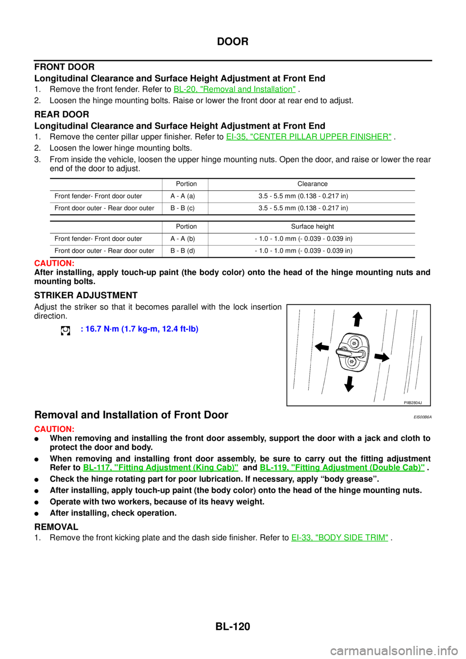
FRONT DOOR
Longitudinal Clearance and Surface Height Adjustment at Front End
1. Remove the front fender. Refer toBL-20, "Removal and Installation".
2. Loosen the hinge mounting bolts. Raise or lower the front door at rear end to adjust.
REAR DOOR
Longitudinal Clearance and Surface Height Adjustment at Front End
1. Remove the center pillar upper finisher. Refer toEI-35, "CENTER PILLAR UPPER FINISHER".
2. Loosen the lower hinge mounting bolts.
3. From inside the vehicle, loosen the upper hinge mounting nuts. Open the door, and raise or lower the rear
end of the door to adjust.
CAUTION:
After installing, apply touch-up paint (the body color) onto the head of the hinge mounting nuts and
mounting bolts.
STRIKER ADJUSTMENT
Adjust the striker so that it becomes parallel with the lock insertion
direction.
Removal and Installation of Front DoorEIS00B6A
CAUTION:
lWhen removing and installing the front door assembly, support the door with a jack and cloth to
protect the door and body.
lWhen removing and installing front door assembly, be sure to carry out the fitting adjustment
Refer toBL-117, "
Fitting Adjustment (King Cab)"andBL-119, "Fitting Adjustment (Double Cab)".
lCheck the hinge rotating part for poor lubrication. If necessary, apply “body grease”.
lAfter installing, apply touch-up paint (the body color) onto the head of the hinge mounting nuts.
lOperate with two workers, because of its heavy weight.
lAfter installing, check operation.
REMOVAL
1. Remove the front kicking plate and the dash side finisher. Refer toEI-33, "BODY SIDE TRIM".
Portion Clearance
Front fender- Front door outer A - A (a) 3.5 - 5.5 mm (0.138 - 0.217 in)
Front door outer - Rear door outer B - B (c) 3.5 - 5.5 mm (0.138 - 0.217 in)
Portion Surface height
Front fender- Front door outer A - A (b) - 1.0 - 1.0 mm (- 0.039 - 0.039 in)
Front door outer - Rear door outer B - B (d) - 1.0 - 1.0 mm (- 0.039 - 0.039 in)
: 16.7 N·m (1.7 kg-m, 12.4 ft-lb)
PIIB2804J
Page 792 of 3171
BR-6
BRAKE PEDAL
BRAKE PEDAL
PFP:46501
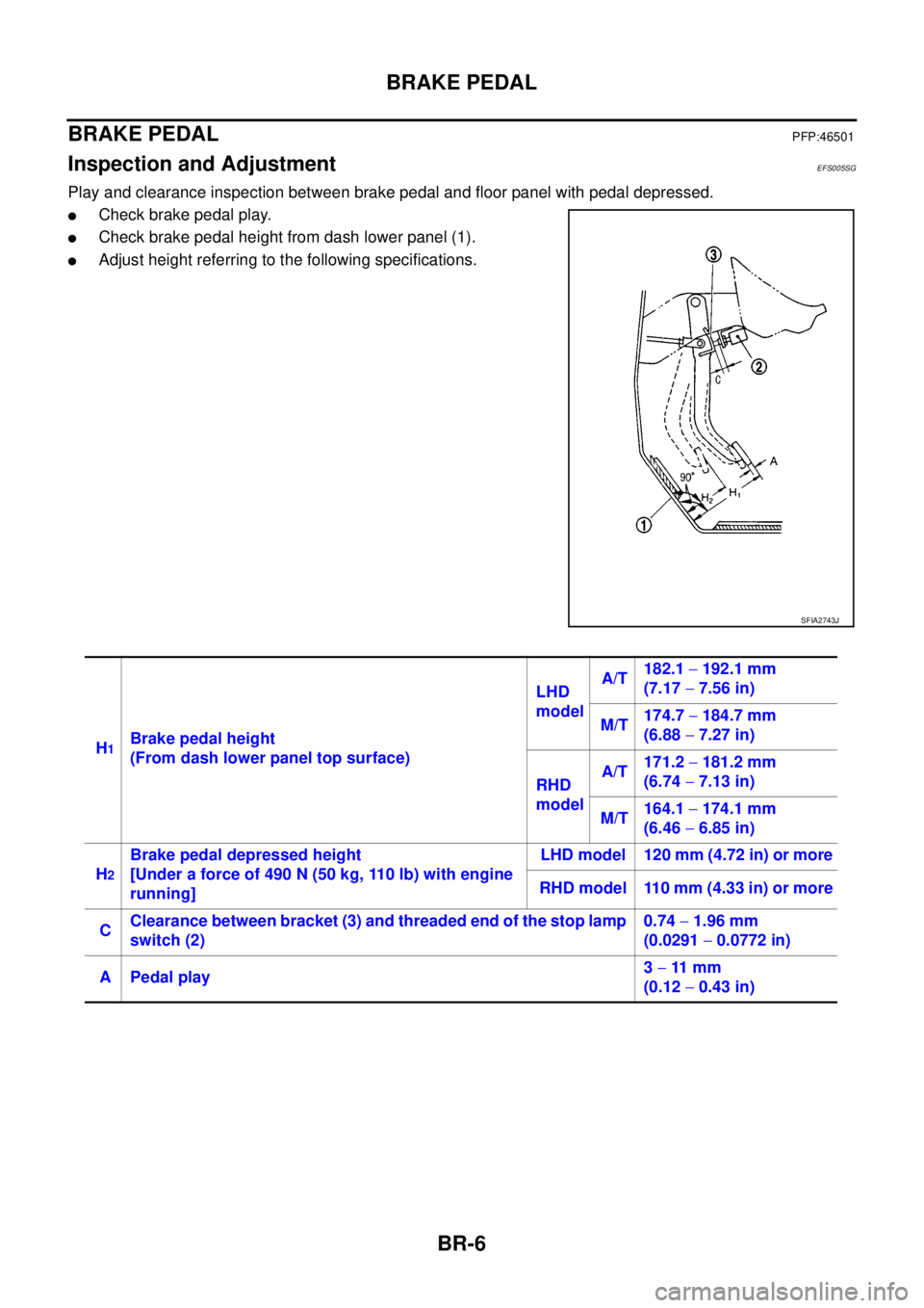
Inspection and AdjustmentEFS005SG
Play and clearance inspection between brake pedal and floor panel with pedal depressed.
lCheck brake pedal play.
lCheck brake pedal height from dash lower panel (1).
lAdjust height referring to the following specifications.
SFIA2743J
H1Brake pedal height
(From dash lower panel top surface)LHD
modelA/T182.1-192.1 mm
(7.17-7.56 in)
M/T174.7-184.7 mm
(6.88-7.27 in)
RHD
modelA/T171.2-181.2 mm
(6.74-7.13 in)
M/T164.1-174.1 mm
(6.46-6.85 in)
H
2
Brake pedal depressed height
[Under a force of 490 N (50 kg, 110 lb) with engine
running]LHD model 120 mm (4.72 in) or more
RHD model 110 mm (4.33 in) or more
CClearance between bracket (3) and threaded end of the stop lamp
switch (2)0.74-1.96 mm
(0.0291-0.0772 in)
A Pedal play3-11 m m
(0.12-0.43 in)
Page 793 of 3171
BRAKE PEDAL
BR-7
C
D
E
G
H
I
J
K
L
MA
B
BR
ADJUSTMENT
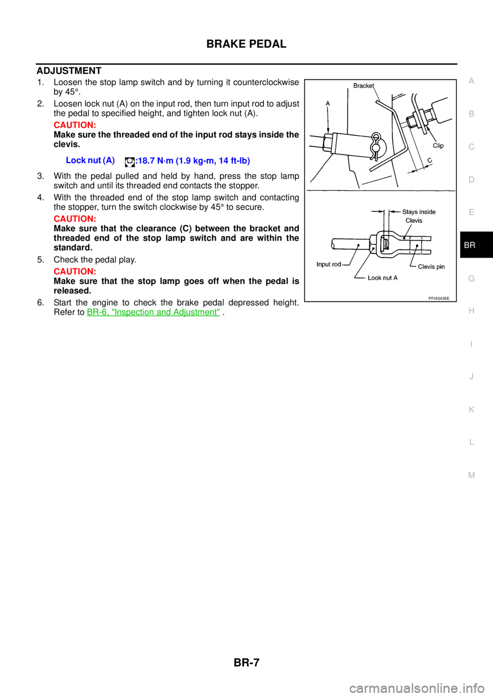
1. Loosen the stop lamp switch and by turning it counterclockwise
by 45°.
2. Loosen lock nut (A) on the input rod, then turn input rod to adjust
the pedal to specified height, and tighten lock nut (A).
CAUTION:
Make sure the threaded end of the input rod stays inside the
clevis.
3. With the pedal pulled and held by hand, press the stop lamp
switch and until its threaded end contacts the stopper.
4. With the threaded end of the stop lamp switch and contacting
the stopper, turn the switch clockwise by 45°to secure.
CAUTION:
Make sure that the clearance (C) between the bracket and
threaded end of the stop lamp switch and are within the
standard.
5. Check the pedal play.
CAUTION:
Make sure that the stop lamp goes off when the pedal is
released.
6. Start the engine to check the brake pedal depressed height.
Refer toBR-6, "
Inspection and Adjustment". Lock nut (A)
:18.7 N·m (1.9 kg-m, 14 ft-lb)
PFIA0436E
Page 807 of 3171
BRAKE BOOSTER
BR-21
C
D
E
G
H
I
J
K
L
MA
B
BR
INSTALLATION
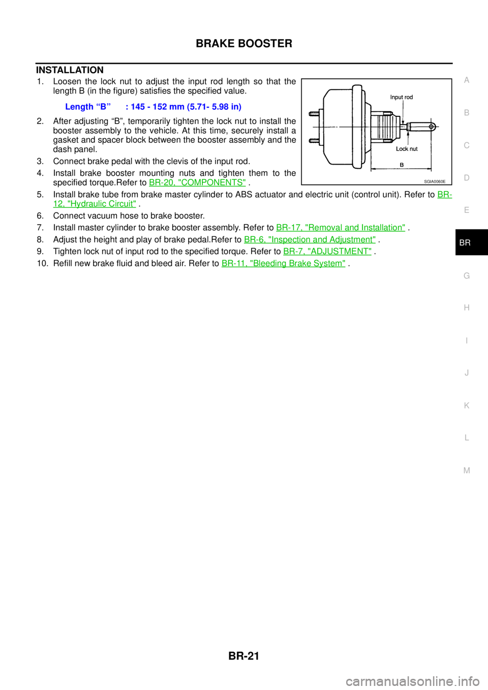
1. Loosen the lock nut to adjust the input rod length so that the
length B (in the figure) satisfies the specified value.
2. After adjusting “B”, temporarily tighten the lock nut to install the
booster assembly to the vehicle. At this time, securely install a
gasket and spacer block between the booster assembly and the
dash panel.
3. Connect brake pedal with the clevis of the input rod.
4. Install brake booster mounting nuts and tighten them to the
specified torque.Refer toBR-20, "
COMPONENTS".
5. Install brake tube from brake master cylinder to ABS actuator and electric unit (control unit). Refer toBR-
12, "Hydraulic Circuit".
6. Connect vacuum hose to brake booster.
7. Install master cylinder to brake booster assembly. Refer toBR-17, "
Removal and Installation".
8. Adjust the height and play of brake pedal.Refer toBR-6, "
Inspection and Adjustment".
9. Tighten lock nut of input rod to the specified torque. Refer toBR-7, "
ADJUSTMENT".
10. Refill new brake fluid and bleed air. Refer toBR-11, "
Bleeding Brake System". Length“B” :145-152mm(5.71-5.98in)
SGIA0060E
Page 874 of 3171
CL-10
CLUTCH MASTER CYLINDER
6. Attach snap pin to clevis pin.
7. Install hose to nipple.
8. After completing this procedure, inspect and adjust for clutch pedal and then bleed the air from the clutch
hydraulic system. Refer toCL-6, "
On-Vehicle Inspection and Adjustment"andCL-8, "Air Bleeding Proce-
dure".
Disassembly and AssemblyECS00ICL
DISASSEMBLY
1. Remove spring pin using a pin punch.
2. Remove nipple and seal from cylinder body.
3. Loosen push rod lock nut then remove clevis and lock nut, if
necessary.
NOTE:
Clutch pedal height is controlled with position of clevis and push
rod.
4. Remove dust cover from cylinder body.
5. Remove stopper ring and stopper. Remove push rod from cylin-
der body while holding it securely to prevent piston assembly
popping out.
6. Remove piston assembly and return spring.
INSPECTION AFTER DISASSEMBLY
Check for any of the conditions shown below. If any malfunction is found, replace the part concerned.
lDamaged cylinder internal wall, foreign matter, wear, corrosion, or pinhole
lDamaged or deformed nipple or reservoir tank
lSettling of return spring
lCracked or deformed dust cover
ASSEMBLY
1. Apply rubber lubricant to the internal surface of cylinder body, the sliding surface of piston assembly, and
piston cup. Insert return spring and piston assembly to cylinder body.
2. Apply silicon grease to push rod and install stopper. Install stopper ring while holding down push rod by
hand to prevent piston assembly from popping out.
3. Install dust cover to cylinder body.
4. Install seal and nipple to cylinder body.
5. Install spring pin using a pin punch.
6. Install clevis to push rod.
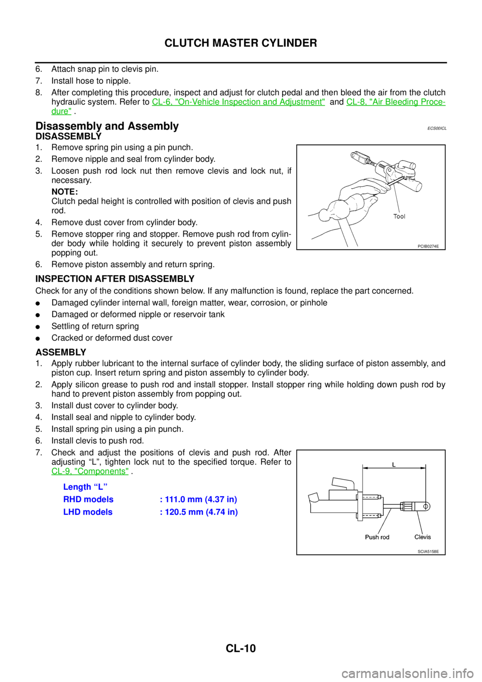
7. Check and adjust the positions of clevis and push rod. After
adjusting “L”, tighten lock nut to the specified torque. Refer to
CL-9, "
Components".
PCIB0274E
Length “L”
RHD models : 111.0 mm (4.37 in)
LHD models : 120.5 mm (4.74 in)
SCIA5158E