2005 NISSAN NAVARA Timing marks
[x] Cancel search: Timing marksPage 846 of 3171
![NISSAN NAVARA 2005 Repair Workshop Manual BRC-24
[ABS]
TROUBLE DIAGNOSIS
BASIC INSPECTION 3 ABS WARNING LAMP AND BRAKE WARNING LAMP INSPECTION
ON and OFF Timing for ABS Warning Lamp, Brake Warning Lamp
´:ON –:OFF
Note 1:Brake warning lamp NISSAN NAVARA 2005 Repair Workshop Manual BRC-24
[ABS]
TROUBLE DIAGNOSIS
BASIC INSPECTION 3 ABS WARNING LAMP AND BRAKE WARNING LAMP INSPECTION
ON and OFF Timing for ABS Warning Lamp, Brake Warning Lamp
´:ON –:OFF
Note 1:Brake warning lamp](/manual-img/5/57362/w960_57362-845.png)
BRC-24
[ABS]
TROUBLE DIAGNOSIS
BASIC INSPECTION 3 ABS WARNING LAMP AND BRAKE WARNING LAMP INSPECTION
ON and OFF Timing for ABS Warning Lamp, Brake Warning Lamp
´:ON –:OFF
Note 1:Brake warning lamp will turn on in case of operating parking brake (switch turned on) or of a actuating brake fluid level switch
(brake fluid is insufficient).
Note 2:After starting engine, turn OFF.
Check the following items when unsuitable for an above condition.
lABS warning lamp: Refer toBRC-28, "Inspection 4 CAN Communication Circuit".
lBrake waning lamp: Refer toBRC-28, "Inspection 4 CAN Communication Circuit",BRC-30, "Inspection 6
Brake Fluid Level Switch Circuit",BRC-32, "Inspection 7 Parking Brake Switch Circuit".
If malfunction is not found, refer toBRC-33, "
Inspection 8 Warning lamp system".
Inspection 1 Wheel Sensor SystemEFS005TZ
Check each part according to CONSULT-II self-diagnostic results, and then identify the parts to be replaced.
CAUTION:
Check each part between wheel sensor terminals.
INSPECTION PROCEDURE
1.CHECK SELF-DIAGNOSTIC RESULTS
Check self-diagnostic results.
Is above displayed in self-diagnosis display items?
YES >> GO TO 2.
NO >> INSPECTION END
2.CHECK TYRE
Check air pressure, wear and size.
Are air pressure, wear and size within standard values?
YES >> GO TO 3.
NO >> Adjust air pressure, or replace tyre.
Condition ABS warning lampBrake warning lamp
[Note 1]Remarks
Ignition SW OFF – — —
Approx. 2 seconds after ignition
switch is turned ON´´[Note 2] —
Approx. 2 seconds later after ignition
switch ON–´[Note 2]Go out 2 seconds after ignition
switch is turned ON.
ABS error´—There is an ABS actuator and
electric unit (control unit) error.
(Power, ground or system mal-
function)
EBD error´´—
Self-diagnostic results
FR RH SENSOR-1,-2
FR LH SENSOR- 1,-2
RR RH SENSOR-1,-2
RR LH SENSOR-1,- 2
ABS SENSOR [MALFUNCTION SIGNAL]
Page 1424 of 3171
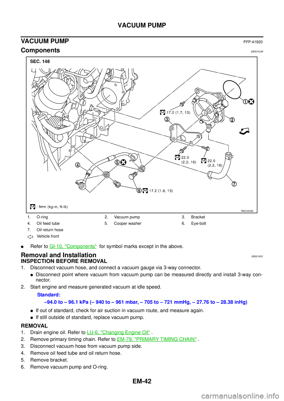
EM-42
VACUUM PUMP
VACUUM PUMP
PFP:41920
ComponentsEBS01EJM
lRefer toGI-10, "Components"for symbol marks except in the above.
Removal and InstallationEBS01E61
INSPECTION BEFORE REMOVAL
1. Disconnect vacuum hose, and connect a vacuum gauge via 3-way connector.
lDisconnect point where vacuum from vacuum pump can be measured directly and install 3-way con-
nector.
2. Start engine and measure generated vacuum at idle speed.
lIf out of standard, check for air suction in vacuum route, and measure again.
lIf still outside of standard, replace vacuum pump.
REMOVAL
1. Drain engine oil. Refer toLU-6, "Changing Engine Oil".
2. Remove primary timing chain. Refer toEM-79, "
PRIMARY TIMING CHAIN".
3. Disconnect vacuum hose from vacuum pump side.
4. Remove oil feed tube and oil return hose.
5. Remove bracket.
6. Remove vacuum pump and O-ring.
1. O-ring 2. Vacuum pump 3. Bracket
4. Oil feed tube 5. Cooper washer 6. Eye-bolt
7. Oil return hose
Vehicle front
PBIC3435E
Standard:
–94.0 to – 96.1 kPa (– 940 to – 961 mbar, – 705 to – 721 mmHg, – 27.76 to – 28.38 inHg)
Page 1431 of 3171
FUEL PUMP
EM-49
C
D
E
F
G
H
I
J
K
L
MA
EM
FUEL PUMPPFP:17042
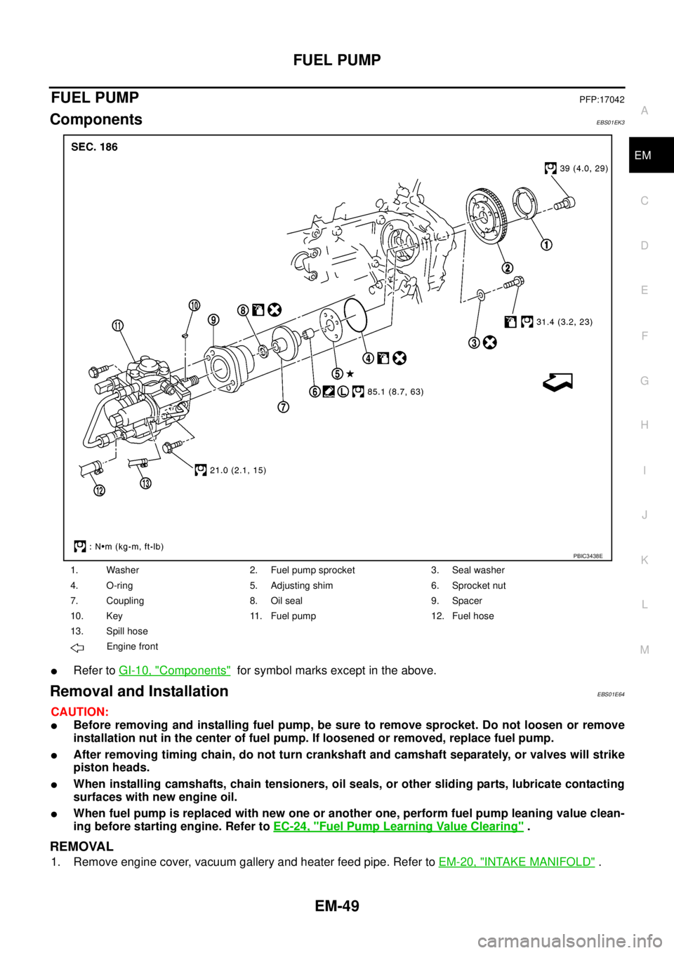
ComponentsEBS01EK3
lRefer toGI-10, "Components"for symbol marks except in the above.
Removal and InstallationEBS01E64
CAUTION:
lBefore removing and installing fuel pump, be sure to remove sprocket. Do not loosen or remove
installation nut in the center of fuel pump. If loosened or removed, replace fuel pump.
lAfter removing timing chain, do not turn crankshaft and camshaft separately, or valves will strike
piston heads.
lWhen installing camshafts, chain tensioners, oil seals, or other sliding parts, lubricate contacting
surfaces with new engine oil.
lWhen fuel pump is replaced with new one or another one, perform fuel pump leaning value clean-
ing before starting engine. Refer toEC-24, "
Fuel Pump Learning Value Clearing".
REMOVAL
1. Remove engine cover, vacuum gallery and heater feed pipe. Refer toEM-20, "INTAKE MANIFOLD".
1. Washer 2. Fuel pump sprocket 3. Seal washer
4. O-ring 5. Adjusting shim 6. Sprocket nut
7. Coupling 8. Oil seal 9. Spacer
10. Key 11. Fuel pump 12. Fuel hose
13. Spill hose
Engine front
PBIC3438E
Page 1442 of 3171
EM-60
CAMSHAFT
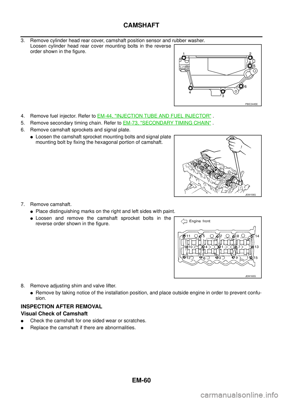
3. Remove cylinder head rear cover, camshaft position sensor and rubber washer.
Loosen cylinder head rear cover mounting bolts in the reverse
order shown in the figure.
4. Remove fuel injector. Refer toEM-44, "
INJECTION TUBE AND FUEL INJECTOR".
5. Remove secondary timing chain. Refer toEM-73, "
SECONDARY TIMING CHAIN".
6. Remove camshaft sprockets and signal plate.
lLoosen the camshaft sprocket mounting bolts and signal plate
mounting bolt by fixing the hexagonal portion of camshaft.
7. Remove camshaft.
lPlace distinguishing marks on the right and left sides with paint.
lLoosen and remove the camshaft sprocket bolts in the
reverse order shown in the figure.
8. Remove adjusting shim and valve lifter.
lRemove by taking notice of the installation position, and place outside engine in order to prevent confu-
sion.
INSPECTION AFTER REMOVAL
Visual Check of Camshaft
lCheck the camshaft for one sided wear or scratches.
lReplace the camshaft if there are abnormalities.
PBIC3445E
JEM159G
JEM160G
Page 1456 of 3171
EM-74
SECONDARY TIMING CHAIN
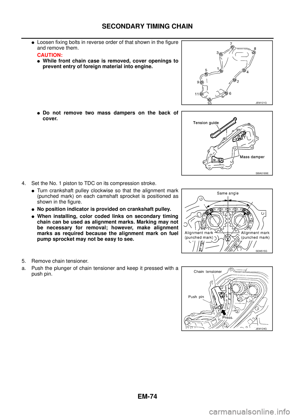
lLoosen fixing bolts in reverse order of that shown in the figure
and remove them.
CAUTION:
lWhile front chain case is removed, cover openings to
prevent entry of foreign material into engine.
lDo not remove two mass dampers on the back of
cover.
4. Set the No. 1 piston to TDC on its compression stroke.
lTurn crankshaft pulley clockwise so that the alignment mark
(punched mark) on each camshaft sprocket is positioned as
showninthefigure.
lNo position indicator is provided on crankshaft pulley.
lWhen installing, color coded links on secondary timing
chain can be used as alignment marks. Marking may not
be necessary for removal; however, make alignment
marks as required because the alignment mark on fuel
pump sprocket may not be easy to see.
5. Remove chain tensioner.
a. Push the plunger of chain tensioner and keep it pressed with a
push pin.
JEM121G
SBIA0189E
SEM515G
JEM124G
Page 1458 of 3171
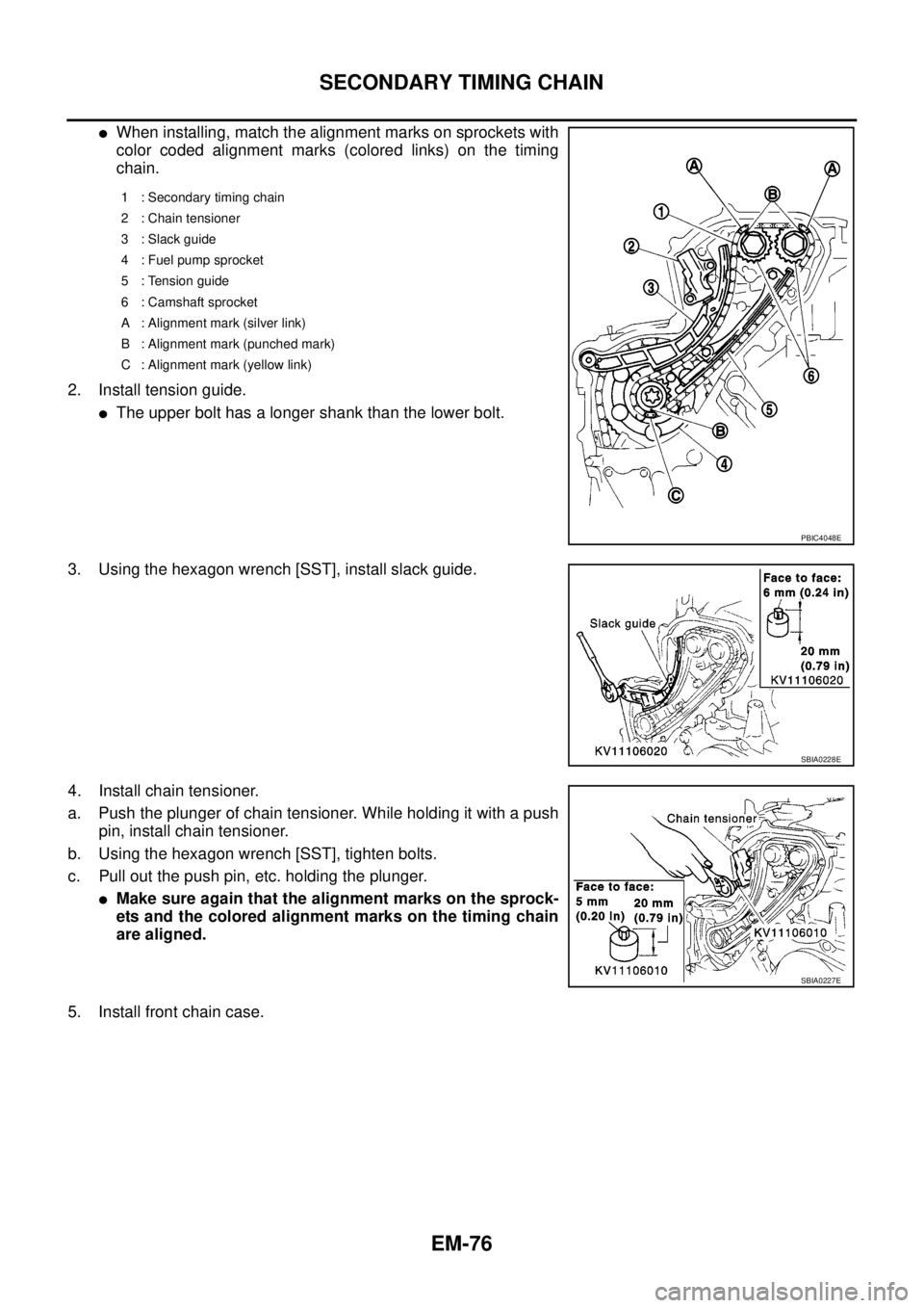
EM-76
SECONDARY TIMING CHAIN
lWhen installing, match the alignment marks on sprockets with
color coded alignment marks (colored links) on the timing
chain.
2. Install tension guide.
lThe upper bolt has a longer shank than the lower bolt.
3. Using the hexagon wrench [SST], install slack guide.
4. Install chain tensioner.
a. Push the plunger of chain tensioner. While holding it with a push
pin, install chain tensioner.
b. Using the hexagon wrench [SST], tighten bolts.
c. Pull out the push pin, etc. holding the plunger.
lMake sure again that the alignment marks on the sprock-
ets and the colored alignment marks on the timing chain
are aligned.
5. Install front chain case.
1 : Secondary timing chain
2 : Chain tensioner
3 : Slack guide
4 : Fuel pump sprocket
5 : Tension guide
6 : Camshaft sprocket
A : Alignment mark (silver link)
B : Alignment mark (punched mark)
C : Alignment mark (yellow link)
PBIC4048E
SBIA0228E
SBIA0227E
Page 1462 of 3171
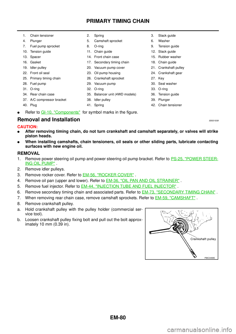
EM-80
PRIMARY TIMING CHAIN
lRefer toGI-10, "Components"for symbol marks in the figure.
Removal and InstallationEBS01E69
CAUTION:
lAfter removing timing chain, do not turn crankshaft and camshaft separately, or valves will strike
piston heads.
lWhen installing camshafts, chain tensioners, oil seals or other sliding parts, lubricate contacting
surfaces with new engine oil.
REMOVAL
1. Remove power steering oil pump and power steering oil pump bracket. Refer toPS-25, "POWER STEER-
ING OIL PUMP".
2. Remove idler pulleys.
3. Remove rocker cover. Refer toEM-56, "
ROCKER COVER".
4. Remove oil pan (upper and lower). Refer toEM-36, "
OIL PAN AND OIL STRAINER".
5. Remove fuel injector. Refer toEM-44, "
INJECTION TUBE AND FUEL INJECTOR".
6. Remove secondary timing chain and associated parts. Refer toEM-73, "
SECONDARY TIMING CHAIN".
7. When removing rear chain case, remove camshaft sprockets. Refer toEM-59, "
CAMSHAFT".
8. Remove crankshaft pulley.
a. Hold crankshaft pulley with the pulley holder (commercial ser-
vice tool).
b. Loosen crankshaft pulley fixing bolt and pull out the bolt approx-
imately 10 mm (0.39 in).
1. Chain tensioner 2. Spring 3. Slack guide
4. Plunger 5. Camshaft sprocket 6. Washer
7. Fuel pump sprocket 8. O-ring 9. Tension guide
10. Tension guide 11. Chain guide 12. Slack guide
13. Spacer 14. Front chain case 15. Rubber washer
16. Gasket 17. Secondary timing chain 18. Chain guide
19. Idler pulley 20. Vacuum pump cover 21. Crankshaft pulley
22. Front oil seal 23. Oil pump housing 24. Crankshaft gear
25. Primary timing chain 26. Crankshaft sprocket 27. Key
28. Fuel pump 29. Vacuum pump 30. Seal washer
31. O-ring 32. O-ring 33. O-ring
34. Rear chain case 35. Balancer unit (4WD models) 36. Tension guide
37. A/C compressor bracket 38. Idler pulley 39. Plunger
40. Plug 41. Spring 42. Chain tensioner
PBIC3469E
Page 1463 of 3171
![NISSAN NAVARA 2005 Repair Workshop Manual PRIMARY TIMING CHAIN
EM-81
C
D
E
F
G
H
I
J
K
L
MA
EM
c. Using the pulley puller [SST], remove crankshaft pulley.
lUse two M6 bolts with approx. 60 mm (2.36 in) shank length
for securing crankshaft pul NISSAN NAVARA 2005 Repair Workshop Manual PRIMARY TIMING CHAIN
EM-81
C
D
E
F
G
H
I
J
K
L
MA
EM
c. Using the pulley puller [SST], remove crankshaft pulley.
lUse two M6 bolts with approx. 60 mm (2.36 in) shank length
for securing crankshaft pul](/manual-img/5/57362/w960_57362-1462.png)
PRIMARY TIMING CHAIN
EM-81
C
D
E
F
G
H
I
J
K
L
MA
EM
c. Using the pulley puller [SST], remove crankshaft pulley.
lUse two M6 bolts with approx. 60 mm (2.36 in) shank length
for securing crankshaft pulley.
9. Remove oil pump housing.
lLoosen bolts in reverse order of that shown in the figure and
remove them.
lU s e t h e s e a l c u t t e r [ S S T: K V 1 0 1111 0 0 ] e t c . f o r r e m o v a l .
10. Remove crankshaft gear.
lRemove crankshaft gear (1) with the following procedure
(4WD models).
a. Make sure that No.1 piston is TDC on its compression stroke.
b. Turn the idler sub gear (3) counterclockwise with snap ring plier
(B) or suitable tool for aligning idler sub gear (3) and idler main
gear (2).
lIf idler gear rotates, hold the flat faces on balancer drive shaft
front end (4).
c. Install internal mechanism securing bolt and plate (Service part:
13012 EB30A and 13013 EB30A) (A) and tighten to the speci-
fied torque.
CAUTION:
lDo not loosen idler gear mounting bolt (5).
lOnly use the genuine internal mechanism securing bolt
and plate (A), or the idler gear (2) and (3) will be damaged.
lDo not remove internal mechanism securing bolt and
plate (A) from idler gear (2) and (3) until crankshaft gear
(1) and all of the parts in connection have been installed.
lIf internal mechanism securing bolt and plate (A) is not
installed, internal mechanism of idler gear (2) and (3) will
disengage after crankshaft gear (1) is removed. This will prohibit the balancer unit from being
reusable.
d. Apply mating marks (C) to crankshaft gear (1) and idler sub gear (3).
e. Remove crankshaft gear (1).
11. Remove front oil seal from oil pump housing.
lPunch out the seal off from the back surface of the oil pump housing using a flat-bladed screwdriver.
CAUTION:
Be careful not to damage oil pump housing.
JEM132G
PBIC3470E
: 4.0 N·m (0.41 kg-m, 35 in-lb)
PBIC3471E