2005 NISSAN NAVARA fuel pressure
[x] Cancel search: fuel pressurePage 802 of 3171
BR-16
LOAD SENSING VALVE
Inspection
EFS006A8
INSPECTION
1. With the vehicle in unladen condition, a person should sit in driver's seat at the rear. Then he/she should
get out of car gently. (This is to stabilize suspension deflection.)
NOTE:
“Unladen condition”: with full coolant, lubricant, 6 to 8 litters of fuel, spare tyre, jack, and hand tools
loaded.
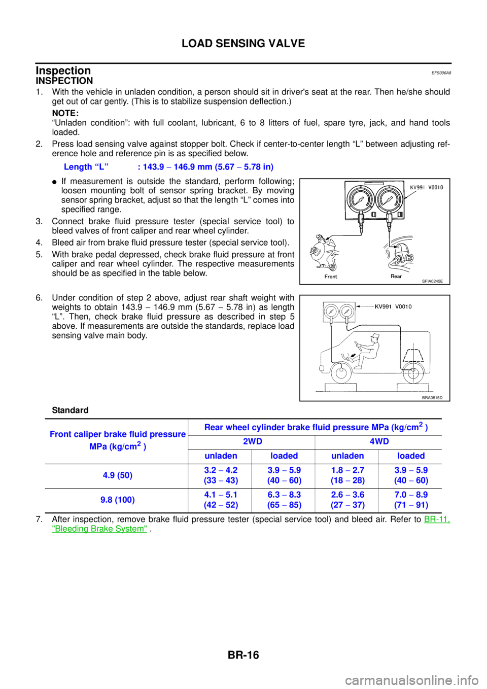
2. Press load sensing valve against stopper bolt. Check if center-to-center length “L” between adjusting ref-
erence hole and reference pin is as specified below.
lIf measurement is outside the standard, perform following;
loosen mounting bolt of sensor spring bracket. By moving
sensor spring bracket, adjust so that the length “L” comes into
specified range.
3. Connect brake fluid pressure tester (special service tool) to
bleed valves of front caliper and rear wheel cylinder.
4. Bleed air from brake fluid pressure tester (special service tool).
5. With brake pedal depressed, check brake fluid pressure at front
caliper and rear wheel cylinder. The respective measurements
should be as specified in the table below.
6. Under condition of step 2 above, adjust rear shaft weight with
weights to obtain 143.9-146.9 mm (5.67-5.78 in) as length
“L”. Then, check brake fluid pressure as described in step 5
above. If measurements are outside the standards, replace load
sensing valve main body.
Standard
7. After inspection, remove brake fluid pressure tester (special service tool) and bleed air. Refer toBR-11,
"Bleeding Brake System". Length “L” : 143.9-146.9 mm (5.67-5.78 in)
SFIA0245E
BRA0515D
Front caliper brake fluid pressure
MPa (kg/cm
2)Rear wheel cylinder brake fluid pressure MPa (kg/cm
2)
2WD 4WD
unladen loaded unladen loaded
4.9 (50)3.2-4.2
(33-43)3.9-5.9
(40-60)1.8-2.7
(18-28)3.9-5.9
(40-60)
9.8 (100)4.1-5.1
(42-52)6.3-8.3
(65-85)2.6-3.6
(27-37)7.0-8.9
(71-91)
Page 908 of 3171
CO-24
THERMOSTAT AND WATER PIPING
Removal and Installation
EBS01E6X
WARNING:
Do not remove radiator cap and/or reservoir tank cap when engine is hot. Serious burns could occur
from high pressure engine coolant escaping from radiator and/or reservoir tank.
REMOVAL
1. Remove front engine undercover and middle engine undercover. Refer toEI-15, "FRONT BUMPER".
2. Drain engine coolant from radiator drain plug at the bottom of radiator, and from water drain plug at the
side of cylinder block. Refer toCO-7, "
Changing Engine Coolant"andEM-110, "CYLINDER BLOCK".
CAUTION:
Perform this step when engine is cold.
3. Remove engine cover. Refer toEM-20, "
INTAKE MANIFOLD".
4. Disconnect radiator hoses (upper and lower) from engine side. Refer toCO-11, "
RADIATOR".
5. Remove air inlet pipe and air duct between air cleaner case and turbocharger. Refer toEM-15, "
AIR
CLEANER AND AIR DUCT"andEM-28, "TURBO CHARGER".
6. Remove water outlet, water inlet and thermostat.
7. Remove thermostat housing.
8. Disconnect heater return hose and water hoses at heater return pipe side, and remove heater return pipe.
9. Remove oil level gauge guide mounting bolt, vacuum hoses (to turbocharger boost control solenoid valve)
and spill hose. Refer toEM-36, "
OIL PAN AND OIL STRAINER",EM-20, "INTAKE MANIFOLD"andEM-
44, "INJECTION TUBE AND FUEL INJECTOR".
10. Disconnect water hoses (to EGR cooler) (A/T models), vacuum hoses and heater feed hose at heater
feed pipe side, and remove heater feed pipe. Refer toEM-20, "
INTAKE MANIFOLD".
INSPECTION AFTER REMOVAL
Thermostat
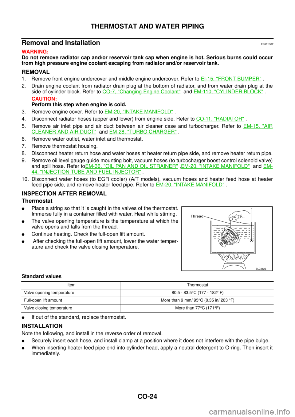
lPlace a string so that it is caught in the valves of the thermostat.
Immerse fully in a container filled with water. Heat while stirring.
lThe valve opening temperature is the temperature at which the
valve opens and falls from the thread.
lContinue heating. Check the full-open lift amount.
lAfter checking the full-open lift amount, lower the water temper-
ature and check the valve closing temperature.
Standard values
lIf out of the standard, replace thermostat.
INSTALLATION
Note the following, and install in the reverse order of removal.
lSecurely insert each hose, and install clamp at a position where it does not interfere with the pipe bulge.
lWhen inserting heater feed pipe end into cylinder head, apply a neutral detergent to O-ring. Then insert it
immediately.
SLC252B
Item Thermostat
Valve opening temperature 80.5 - 83.5°C (177 - 182°F)
Full-open lift amount More than 9 mm/ 95°C (0.35 in/ 203°F)
Valve closing temperature More than 77°C(171°F)
Page 911 of 3171

DI-1
DRIVER INFORMATION SYSTEM
K ELECTRICAL
CONTENTS
C
D
E
F
G
H
I
J
L
M
SECTIONDI
A
B
DI
DRIVER INFORMATION SYSTEM
PRECAUTION ............................................................ 3
Precautions for Supplemental Restraint System
(SRS)“AIRBAG”and“SEATBELTPRE-TEN-
SIONER” .................................................................. 3
Wiring Diagrams and Trouble Diagnosis .................. 3
COMBINATION METERS ........................................... 4
System Description .................................................. 4
UNIFIED METER CONTROL UNIT ...................... 4
POWER SUPPLY AND GROUND CIRCUIT ........ 4
SPEEDOMETER ................................................... 4
TACHOMETER ..................................................... 4
WATER TEMPERATURE GAUGE ........................ 4
FUEL GAUGE ....................................................... 5
ODO/TRIP METER ............................................... 5
TRIP COMPUTER ................................................ 5
ENGINE OIL MAINTENANCE INFORMATION..... 6
METER ILLUMINATION CONTROL ..................... 6
CLOCK .................................................................. 6
AMBIENT AIR TEMPERATURE INDICATION ...... 6
Component Parts and Harness Connector Location..... 7
Arrangement of Combination Meter ......................... 8
Internal Circuit .......................................................... 9
Wiring Diagram — METER — ................................ 10
Terminals and Reference Value for Combination
Meter ...................................................................... 12
Self-Diagnosis Mode of Combination Meter ........... 13
FUNCTION .......................................................... 13
OPERATION PROCEDURE ............................... 13
TEST ITEM ......................................................... 13
CONSULT-II Function (METER) ............................. 15
CONSULT-II BASIC OPERATION ....................... 15
SELF-DIAG RESULTS ........................................ 16
DATA MONITOR ................................................. 17
Trouble Diagnosis .................................................. 18
HOW TO PERFORM TROUBLE DIAGNOSIS ... 18
PRELIMINARY CHECK ...................................... 19
Symptom Chart ...................................................... 19
Power Supply and Ground Circuit Inspection ........ 19
Vehicle Speed Signal Inspection ............................ 20
Engine Speed Signal Inspection ............................ 21Engine Coolant Temperature Signal Inspection ..... 21
Fuel Level Sensor Signal Inspection ...................... 22
Ambient Sensor Signal Inspection .......................... 24
Fuel Gauge Fluctuates, Indicates Wrong Value, or
Varies ...................................................................... 25
Fuel Gauge Does Not Move to Full position ........... 25
DTC [U1000] CAN Communication Circuit ............. 26
DTC [B2205] Vehicle Speed Circuit ........................ 26
Electrical Components Inspection .......................... 27
FUEL LEVEL SENSOR UNIT CHECK ................ 27
AMBIENT SENSOR CHECK ............................... 27
Removal and Installation of Combination Meter ..... 27
WARNING LAMPS .................................................... 28
System Description ................................................. 28
OIL PRESSURE WARNING LAMP ..................... 28
Component Parts and Harness Connector Location... 28
Schematic ............................................................... 29
Wiring Diagram — WARN — .................................. 30
A/T MODELS ....................................................... 30
M/T MODELS ...................................................... 37
Oil Pressure Warning Lamp Stays Off (Ignition
Switch ON) ............................................................. 44
Oil Pressure Warning Lamp Does Not Turn Off (Oil
Pressure Is Normal) ................................................ 45
Oil Pressure Warning Lamp Keeps Blinking (Oil
Level Is Normal) ..................................................... 46
Component Inspection ............................................ 47
OIL PRESSURE SWITCH ................................... 47
OIL LEVEL SENSOR .......................................... 47
A/T INDICATOR ........................................................ 48
System Description ................................................. 48
Wiring Diagram — AT/IND — ................................. 49
A/T Indicator Does Not Illuminate ........................... 50
WARNING CHIME ..................................................... 51
System Description ................................................. 51
POWER SUPPLY AND GROUND CIRCUIT ....... 51
LIGHT WARNING CHIME ................................... 51
KEY REMINDER WARNING CHIME .................. 51
LOW-FUEL WARNING CHIME ........................... 51
SEAT BELT WARNING CHIME ........................... 52
Page 927 of 3171
COMBINATION METERS
DI-17
C
D
E
F
G
H
I
J
L
MA
B
DI
DATA MONITOR
Operation Procedure
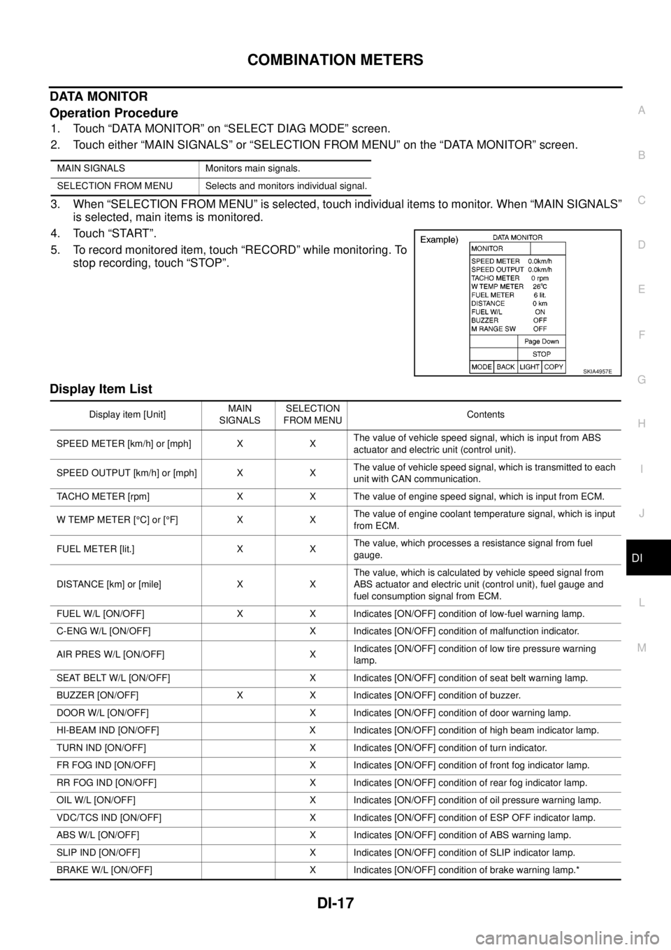
1. Touch “DATA MONITOR” on “SELECT DIAG MODE” screen.
2. Touch either “MAIN SIGNALS” or “SELECTION FROM MENU” on the “DATA MONITOR” screen.
3. When “SELECTION FROM MENU” is selected, touch individual items to monitor. When “MAIN SIGNALS”
is selected, main items is monitored.
4. Touch “START”.
5. To record monitored item, touch “RECORD” while monitoring. To
stop recording, touch “STOP”.
Display Item List
MAIN SIGNALS Monitors main signals.
SELECTION FROM MENU Selects and monitors individual signal.
SKIA4957E
Display item [Unit]MAIN
SIGNALSSELECTION
FROM MENUContents
SPEED METER [km/h] or [mph] X XThe value of vehicle speed signal, which is input from ABS
actuator and electric unit (control unit).
SPEED OUTPUT [km/h] or [mph] X XThe value of vehicle speed signal, which is transmitted to each
unit with CAN communication.
TACHO METER [rpm] X X The value of engine speed signal, which is input from ECM.
W TEMP METER [°C] or [°F] X XThe value of engine coolant temperature signal, which is input
from ECM.
FUEL METER [lit.] X XThe value, which processes a resistance signal from fuel
gauge.
DISTANCE [km] or [mile] X XThe value, which is calculated by vehicle speed signal from
ABS actuator and electric unit (control unit), fuel gauge and
fuel consumption signal from ECM.
FUEL W/L [ON/OFF] X X Indicates [ON/OFF] condition of low-fuel warning lamp.
C-ENG W/L [ON/OFF] X Indicates [ON/OFF] condition of malfunction indicator.
AIR PRES W/L [ON/OFF] XIndicates [ON/OFF] condition of low tire pressure warning
lamp.
SEAT BELT W/L [ON/OFF] X Indicates [ON/OFF] condition of seat belt warning lamp.
BUZZER [ON/OFF] X X Indicates [ON/OFF] condition of buzzer.
DOOR W/L [ON/OFF] X Indicates [ON/OFF] condition of door warning lamp.
HI-BEAM IND [ON/OFF] X Indicates [ON/OFF] condition of high beam indicator lamp.
TURN IND [ON/OFF] X Indicates [ON/OFF] condition of turn indicator.
FR FOG IND [ON/OFF] X Indicates [ON/OFF] condition of front fog indicator lamp.
RR FOG IND [ON/OFF] X Indicates [ON/OFF] condition of rear fog indicator lamp.
OIL W/L [ON/OFF] X Indicates [ON/OFF] condition of oil pressure warning lamp.
VDC/TCS IND [ON/OFF] X Indicates [ON/OFF] condition of ESP OFF indicator lamp.
ABS W/L [ON/OFF] X Indicates [ON/OFF] condition of ABS warning lamp.
SLIP IND [ON/OFF] X Indicates [ON/OFF] condition of SLIP indicator lamp.
BRAKE W/L [ON/OFF] X Indicates [ON/OFF] condition of brake warning lamp.*
Page 929 of 3171
COMBINATION METERS
DI-19
C
D
E
F
G
H
I
J
L
MA
B
DI
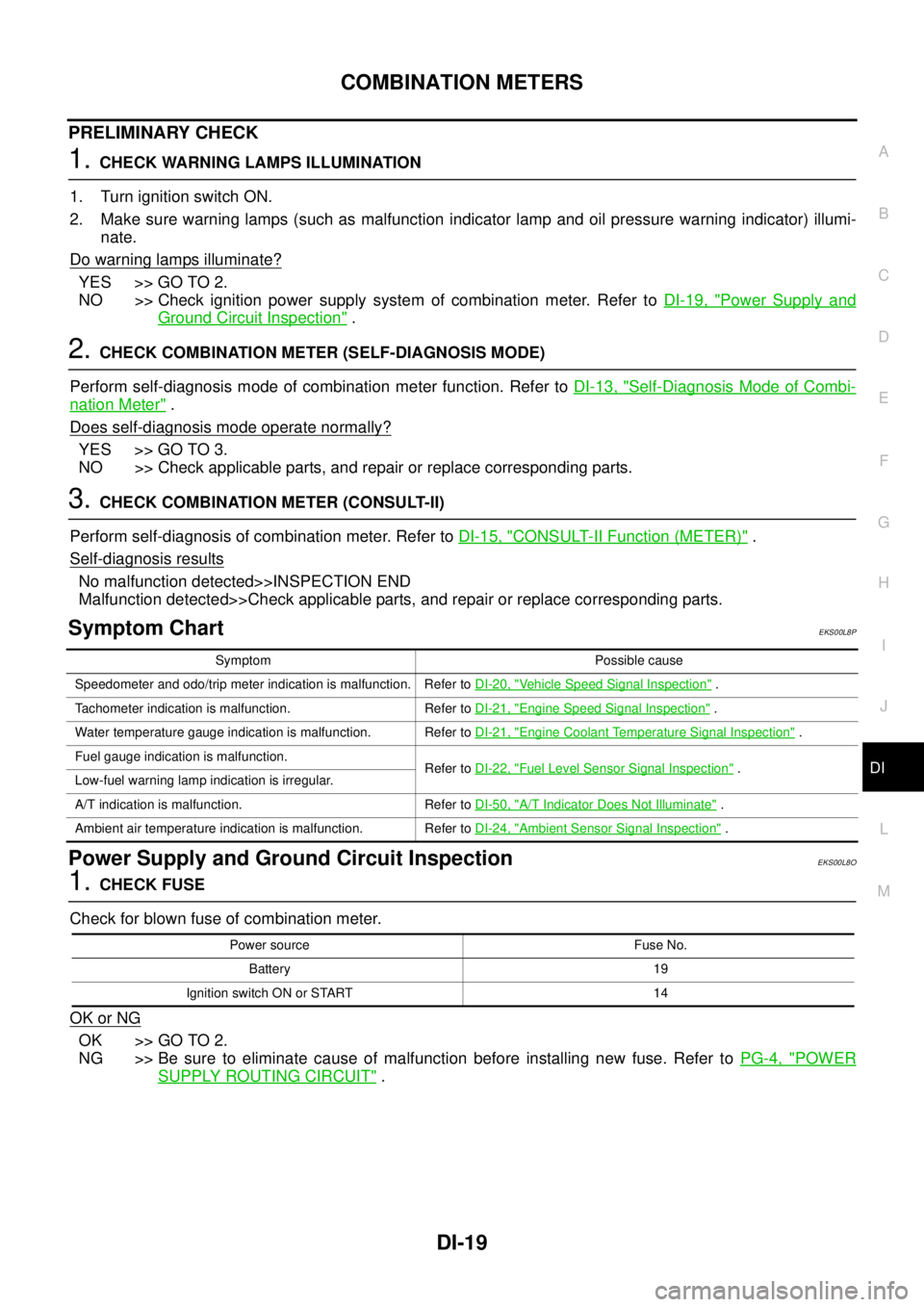
PRELIMINARY CHECK
1.CHECK WARNING LAMPS ILLUMINATION
1. Turn ignition switch ON.
2. Make sure warning lamps (such as malfunction indicator lamp and oil pressure warning indicator) illumi-
nate.
Do warning lamps illuminate?
YES >> GO TO 2.
NO >> Check ignition power supply system of combination meter. Refer toDI-19, "
Power Supply and
Ground Circuit Inspection".
2.CHECK COMBINATION METER (SELF-DIAGNOSIS MODE)
Perform self-diagnosis mode of combination meter function. Refer toDI-13, "
Self-Diagnosis Mode of Combi-
nation Meter".
Does self-diagnosis mode operate normally?
YES >> GO TO 3.
NO >> Check applicable parts, and repair or replace corresponding parts.
3.CHECK COMBINATION METER (CONSULT-II)
Perform self-diagnosis of combination meter. Refer toDI-15, "
CONSULT-II Function (METER)".
Self-diagnosis results
No malfunction detected>>INSPECTION END
Malfunction detected>>Check applicable parts, and repair or replace corresponding parts.
Symptom ChartEKS00L8P
Power Supply and Ground Circuit InspectionEKS00L8O
1.CHECK FUSE
Check for blown fuse of combination meter.
OK or NG
OK >> GO TO 2.
NG >> Be sure to eliminate cause of malfunction before installing new fuse. Refer toPG-4, "
POWER
SUPPLY ROUTING CIRCUIT".
Symptom Possible cause
Speedometer and odo/trip meter indication is malfunction. Refer toDI-20, "
Vehicle Speed Signal Inspection".
Tachometer indication is malfunction. Refer toDI-21, "
Engine Speed Signal Inspection".
Water temperature gauge indication is malfunction. Refer toDI-21, "
Engine Coolant Temperature Signal Inspection".
Fuel gauge indication is malfunction.
Refer toDI-22, "
Fuel Level Sensor Signal Inspection".
Low-fuel warning lamp indication is irregular.
A/T indication is malfunction. Refer toDI-50, "
A/T Indicator Does Not Illuminate".
Ambient air temperature indication is malfunction. Refer toDI-24, "
Ambient Sensor Signal Inspection".
Power source Fuse No.
Battery 19
Ignition switch ON or START 14
Page 985 of 3171

EC-5
C
D
E
F
G
H
I
J
K
L
M
ECA . 303
ECM Terminals and Reference Value .................. 303
Wiring Diagram .................................................... 304
Diagnostic Procedure ........................................... 305
Component Inspection ......................................... 307
Removal and Installation ...................................... 308
TC BOOST CONTROL SOLENOID VALVE ........... 309
Description ........................................................... 309
ECM Terminals and Reference Value .................. 310
Wiring Diagram ..................................................... 311
Diagnostic Procedure ........................................... 312
Component Inspection ......................................... 313
Removal and Installation ...................................... 313
INTAKE AIR CONTROL VALVE CONTROL SOLE-
NOID VALVE ........................................................... 314
Description ........................................................... 314
ECM Terminals and Reference Value .................. 314
Wiring Diagram .................................................... 315
Diagnostic Procedure ........................................... 316
Component Inspection ......................................... 318
HEAT UP SWITCH .................................................. 319
Description ........................................................... 319
CONSULT-II Reference Value in Data Monitor Mode
. 319
ECM Terminals and Reference Value .................. 319
Wiring Diagram .................................................... 320
Diagnostic Procedure ........................................... 321
Component Inspection ......................................... 324
REFRIGERANT PRESSURE SENSOR ................. 325
Component Description ........................................ 325
ECM Terminals and Reference Value .................. 325
Wiring Diagram .................................................... 326
Diagnostic Procedure ........................................... 327
Removal and Installation ...................................... 329
BRAKE SWITCH .................................................... 330
Description ........................................................... 330
CONSULT-II Reference Value in Data Monitor Mode.330
ECM Terminals and Reference Value ...................330
Wiring Diagram .....................................................331
Diagnostic Procedure ...........................................332
Component Inspection ..........................................341
PNP SWITCH ..........................................................342
Description ............................................................342
CONSULT-II Reference Value in Data Monitor Mode
.342
ECM Terminals and Reference Value ...................342
Wiring Diagram .....................................................343
Diagnostic Procedure ...........................................344
START SIGNAL ......................................................348
Wiring Diagram .....................................................348
Diagnostic Procedure ...........................................349
ASCD INDICATOR ..................................................351
Component Description ........................................351
Wiring Diagram .....................................................352
Diagnostic Procedure ...........................................353
MI & DATA LINK CONNECTORS ...........................354
Wiring Diagram .....................................................354
AUTOMATIC SPEED CONTROL DEVICE (ASCD). 355
System Description ...............................................355
Component Description ........................................356
SERVICE DATA AND SPECIFICATIONS (SDS) ....357
General Specifications ..........................................357
Mass Air Flow Sensor ...........................................357
Intake Air Temperature Sensor .............................357
Engine Coolant Temperature Sensor ...................357
Fuel Rail Pressure Sensor ....................................357
Fuel Injector ..........................................................357
Glow Plug .............................................................357
EGR Volume Control Valve ..................................357
Crankshaft Position Sensor ..................................357
Camshaft Position Sensor ....................................357
Fuel Pump ............................................................358
Page 998 of 3171

EC-18
ENGINE CONTROL SYSTEM
System Chart
EBS01KCD
*1: The input signal is sent to the ECM through CAN communication line.
*2: The output signal is sent from the ECM through CAN communication line.
Fuel Injection Control SystemEBS01KCE
SYSTEM DESCRIPTION
Three types of fuel injection control are provided to accommodate engine operating conditions; normal control,
idle control and start control. The ECM determines the appropriate fuel injection control. Under each control,
the amount of fuel injected is adjusted to improve engine performance.
Pulse signals are sent to fuel injectors according to the input signals to adjust the amount of fuel injected to
preset value.
START CONTROL
Input/Output Signal Chart
Input (Sensor) ECM Function Output (Actuator)
lAccelerator pedal position sensor
lFuel rail pressure sensor
lFuel pump temperature sensor
lEngine coolant temperature sensor
lMass air flow sensor
lIntake air temperature sensor
lCrankshaft position sensor
lCamshaft position sensor
lTurbocharger boost sensor
lWheel sensor*1
lIgnition switch
lASCD steering switch
lASCD brake switch
lASCD clutch switch
lSt o p l a m p s w it c h
lAir conditioner switch*1
lFront air control*1
lPark/neutral position switch
lHeat up switch
lRefrigerant pressure sensor
lBattery voltageFuel injection control Fuel injector and Fuel pump
Fuel injection timing control Fuel injector and Fuel pump
Fuel cut control Fuel injector and Fuel pump
Glow control system
Glow relay and glow indicator lamp*
2
ASCD vehicle speed control Fuel injector and Fuel pump
On board diagnostic system
Malfunction indicator (MI)*
2
EGR volume control EGR volume control valve
Cooling fan control
Cooling fan relay*
2
Turbocharger boost controlTurbocharger boost control solenoid
valve
Intake air control valve controlIntake air control valve control solenoid
valve
Air conditioning cut control
Air conditioner relay*
2
Sensor Input Signal to ECM ECM Function Actuator
Engine coolant temperature sensor Engine coolant temperature
Fuel injection
control (start
control)Fuel injector
Fuel pump Crankshaft position sensor Engine speed
Camshaft position sensor Piston position
Ignition switch Start signal
Fuel rail pressure sensor Fuel rail pressure
Page 999 of 3171
ENGINE CONTROL SYSTEM
EC-19
C
D
E
F
G
H
I
J
K
L
MA
EC
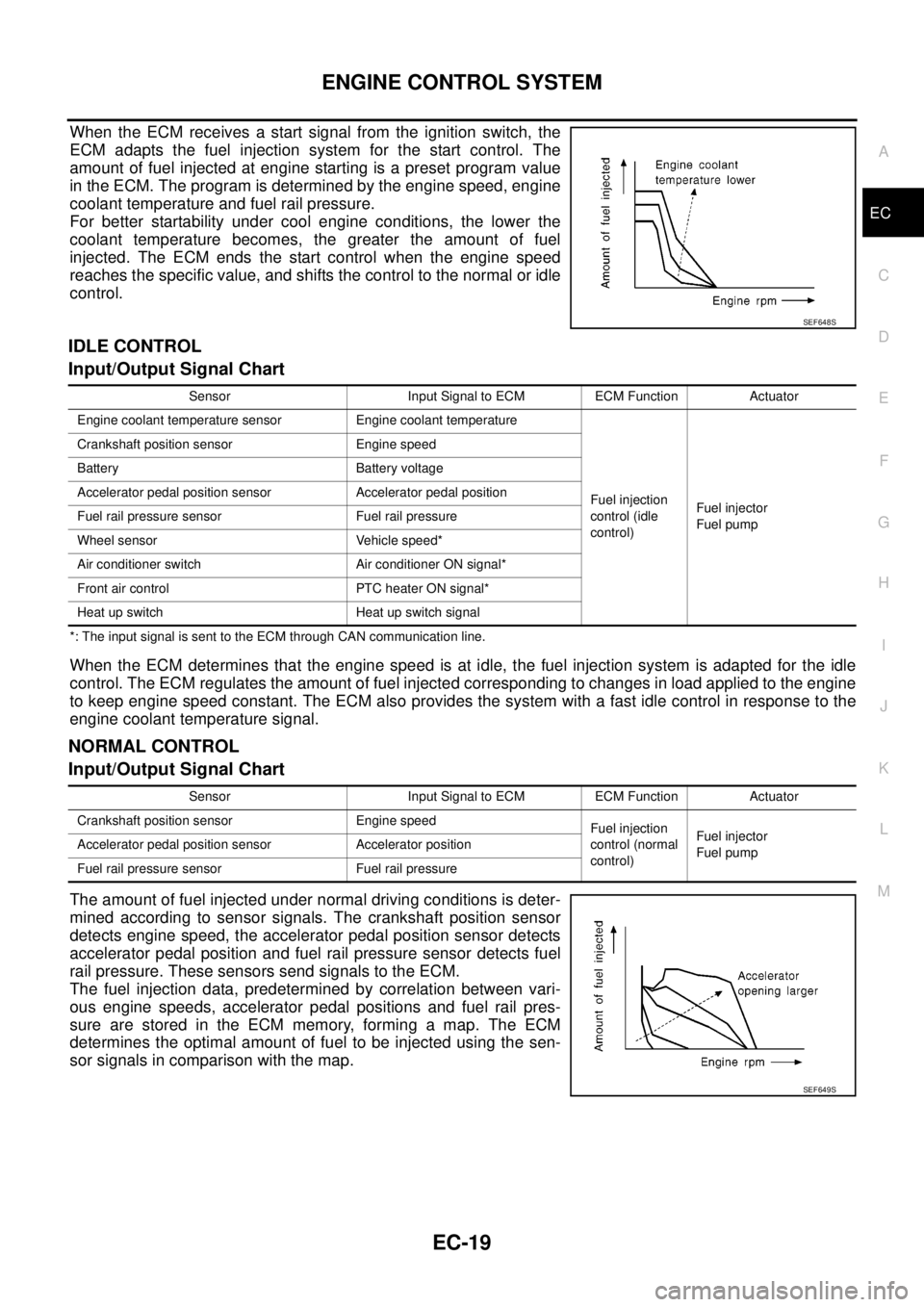
When the ECM receives a start signal from the ignition switch, the
ECM adapts the fuel injection system for the start control. The
amount of fuel injected at engine starting is a preset program value
in the ECM. The program is determined by the engine speed, engine
coolant temperature and fuel rail pressure.
For better startability under cool engine conditions, the lower the
coolant temperature becomes, the greater the amount of fuel
injected. The ECM ends the start control when the engine speed
reaches the specific value, and shifts the control to the normal or idle
control.
IDLE CONTROL
Input/Output Signal Chart
*: The input signal is sent to the ECM through CAN communication line.
When the ECM determines that the engine speed is at idle, the fuel injection system is adapted for the idle
control. The ECM regulates the amount of fuel injected corresponding to changes in load applied to the engine
to keep engine speed constant. The ECM also provides the system with a fast idle control in response to the
engine coolant temperature signal.
NORMAL CONTROL
Input/Output Signal Chart
The amount of fuel injected under normal driving conditions is deter-
mined according to sensor signals. The crankshaft position sensor
detects engine speed, the accelerator pedal position sensor detects
accelerator pedal position and fuel rail pressure sensor detects fuel
rail pressure. These sensors send signals to the ECM.
The fuel injection data, predetermined by correlation between vari-
ous engine speeds, accelerator pedal positions and fuel rail pres-
sure are stored in the ECM memory, forming a map. The ECM
determines the optimal amount of fuel to be injected using the sen-
sor signals in comparison with the map.
SEF648S
Sensor Input Signal to ECM ECM Function Actuator
Engine coolant temperature sensor Engine coolant temperature
Fuel injection
control (idle
control)Fuel injector
Fuel pump Crankshaft position sensor Engine speed
Battery Battery voltage
Accelerator pedal position sensor Accelerator pedal position
Fuel rail pressure sensor Fuel rail pressure
Wheel sensor Vehicle speed*
Air conditioner switch Air conditioner ON signal*
Front air control PTC heater ON signal*
Heat up switch Heat up switch signal
Sensor Input Signal to ECM ECM Function Actuator
Crankshaft position sensor Engine speed
Fuel injection
control (normal
control)Fuel injector
Fuel pump Accelerator pedal position sensor Accelerator position
Fuel rail pressure sensor Fuel rail pressure
SEF649S