2005 NISSAN NAVARA driver seat adjustment
[x] Cancel search: driver seat adjustmentPage 585 of 3171

BL-1
BODY, LOCK & SECURITY SYSTEM
IBODY
CONTENTS
C
D
E
F
G
H
J
K
L
M
SECTIONBL
A
B
BL
BODY, LOCK & SECURITY SYSTEM
PRECAUTIONS .......................................................... 4
Precautions for Supplemental Restraint System
(SRS)“AIRBAG”and“SEATBELTPRE-TEN-
SIONER” .................................................................. 4
Precautions for procedures with out cowl top cover..... 4
Precautions for Work ................................................ 4
Wiring Diagrams and Trouble Diagnosis .................. 4
PREPARATION ........................................................... 5
Commercial Service Tools ........................................ 5
SQUEAK AND RATTLE TROUBLE DIAGNOSES..... 6
Work Flow ................................................................ 6
CUSTOMER INTERVIEW ..................................... 6
DUPLICATE THE NOISE AND TEST DRIVE ....... 7
CHECK RELATED SERVICE BULLETINS ........... 7
LOCATE THE NOISE AND IDENTIFY THE
ROOT CAUSE ...................................................... 7
REPAIR THE CAUSE ........................................... 7
CONFIRM THE REPAIR ....................................... 8
Generic Squeak and Rattle Troubleshooting ........... 8
INSTRUMENT PANEL .......................................... 8
CENTER CONSOLE ............................................. 8
DOORS ................................................................. 8
TRUNK .................................................................. 9
SUNROOF/HEADLINING ..................................... 9
SEATS ................................................................... 9
UNDERHOOD ....................................................... 9
Diagnostic Worksheet ............................................ 10
HOOD ....................................................................... 12
Fitting Adjustment .................................................. 12
LONGITUDINAL AND LATERAL CLEARANCE
ADJUSTMENT .................................................... 13
FRONT END HEIGHT ADJUSTMENT ............... 13
SURFACE HEIGHT ADJUSTMENT ................... 13
Removal and Installation of Hood Assembly .......... 14
REMOVAL ........................................................... 14
INSTALLATION ................................................... 14
Removal and Installation of Hood Hinge ................ 15
REMOVAL ........................................................... 15
INSTALLATION ................................................... 15
Removal and Installation of Hood Lock Control ..... 15REMOVAL ........................................................... 15
INSTALLATION ................................................... 16
Hood Lock Control Inspection ................................ 17
RADIATOR CORE SUPPORT .................................. 18
Removal and Installation ........................................ 18
REMOVAL ........................................................... 18
INSTALLATION ................................................... 19
FRONT FENDER ...................................................... 20
Removal and Installation ........................................ 20
REMOVAL ........................................................... 20
INSTALLATION ................................................... 20
POWER DOOR LOCK SYSTEM .............................. 21
Component Parts and Harness Connector Location... 21
KING CAB ........................................................... 21
DOUBLE CAB ..................................................... 22
System Description ................................................. 23
OUTLINE ............................................................. 24
CAN Communication System Description .............. 25
CAN Communication Unit ....................................... 25
Schematic ............................................................... 26
Wiring Diagram —D/LOCK— ................................. 27
Terminals and Reference Value for BCM ............... 34
CONSULT-II Function (BCM) ................................. 35
CONSULT-II BASIC OPERATION PROCEDURE
... 35
CONSULT-II APPLICATION ITEMS .................... 36
Work Flow ............................................................... 37
Trouble Diagnoses Chart by Symptom ................... 37
Check Power Supply and Ground Circuit ............... 37
Check Door Switch ................................................. 39
CHECK DOOR SWITCH (DOUBLE CAB) .......... 39
CHECK DOOR SWITCH (KING CAB) ................ 41
Check Key Switch ................................................... 43
Check Door Key Cylinder Switch (LHD Model Only)... 45
Check Front Door Lock Actuator (Driver Side) ....... 48
Check Front Door Lock Actuator (Passenger Side)... 49
Check Front Door Lock Actuator Switch ................. 50
Check Rear Door Lock Actuator LH (Double Cab
Model) ..................................................................... 50
Check Rear Door Lock Actuator RH (Double Cab
Page 588 of 3171

BL-4
PRECAUTIONS
PRECAUTIONS
PFP:00001
Precautions for Supplemental Restraint System (SRS) “AIR BAG” and “SEAT
BELT PRE-TENSIONER”
EIS00DHW
The Supplemental Restraint System such as “AIR BAG” and “SEAT BELT PRE-TENSIONER”, used along
with a front seat belt, helps to reduce the risk or severity of injury to the driver and front passenger for certain
types of collision. Information necessary to service the system safely is included in the SRS and SB section of
this Service Manual.
WARNING:
lTo avoid rendering the SRS inoperative, which could increase the risk of personal injury or death
in the event of a collision which would result in air bag inflation, all maintenance must be per-
formed by an authorized NISSAN/INFINITI dealer.
lImproper maintenance, including incorrect removal and installation of the SRS, can lead to per-
sonal injury caused by unintentional activation of the system. For removal of Spiral Cable and Air
Bag Module, see the SRS section.
lDo not use electrical test equipment on any circuit related to the SRS unless instructed to in this
Service Manual. SRS wiring harnesses can be identified by yellow and/or orange harnesses or
harness connectors.
Precautions for procedures with out cowl top coverEIS00DHY
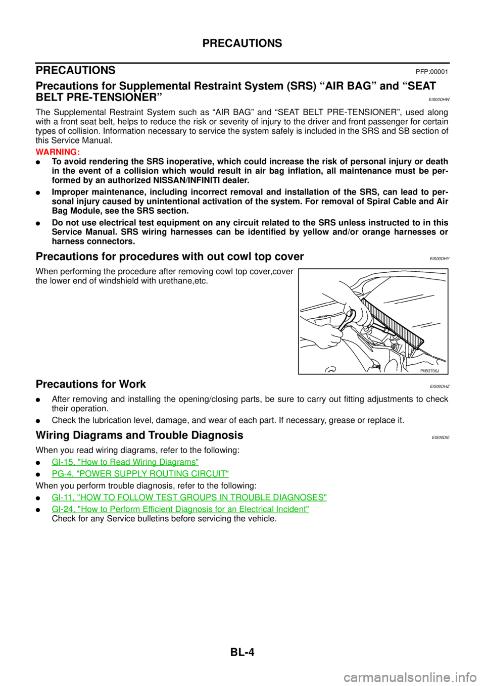
When performing the procedure after removing cowl top cover,cover
the lower end of windshield with urethane,etc.
Precautions for WorkEIS00DHZ
lAfter removing and installing the opening/closing parts, be sure to carry out fitting adjustments to check
their operation.
lCheck the lubrication level, damage, and wear of each part. If necessary, grease or replace it.
Wiring Diagrams and Trouble DiagnosisEIS00DI0
When you read wiring diagrams, refer to the following:
lGI-15, "How to Read Wiring Diagrams"
lPG-4, "POWER SUPPLY ROUTING CIRCUIT"
When you perform trouble diagnosis, refer to the following:
lGI-11, "HOW TO FOLLOW TEST GROUPS IN TROUBLE DIAGNOSES"
lGI-24, "How to Perform Efficient Diagnosis for an Electrical Incident"
Check for any Service bulletins before servicing the vehicle.
PIIB3706J
Page 2168 of 3171

FRONT FOG LAMP
LT-85
C
D
E
F
G
H
I
J
L
MA
B
LT
Aiming AdjustmentEKS00P4D
The fog lamp is a semi-sealed beam type which uses a replaceable halogen bulb. Before performing aiming
adjustment, make sure of the following.
lKeep all tires inflated to correct pressure.
lPlace vehicle on level surface.
lSee that vehicle is unloaded (except for full levels of coolant, engine oil and fuel, and spare tire, jack, and
tools). Have the driver or equivalent weight placed in driver's seat.
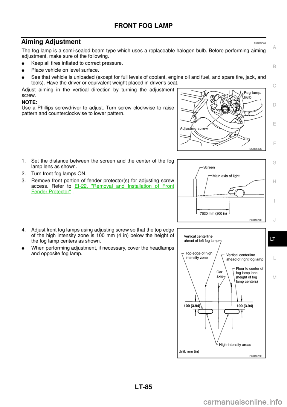
Adjust aiming in the vertical direction by turning the adjustment
screw.
NOTE:
Use a Phillips screwdriver to adjust. Turn screw clockwise to raise
pattern and counterclockwise to lower pattern.
1. Set the distance between the screen and the center of the fog
lamp lens as shown.
2. Turn front fog lamps ON.
3. Remove front portion of fender protector(s) for adjusting screw
access. Refer toEI-22, "
Removal and Installation of Front
Fender Protector".
4. Adjust front fog lamps using adjusting screw so that the top edge
of the high intensity zone is 100 mm (4 in) below the height of
the fog lamp centers as shown.
lWhen performing adjustment, if necessary, cover the headlamps
and opposite fog lamp.
SKIB6539E
PKIB1672E
PKIB1673E
Page 2736 of 3171
![NISSAN NAVARA 2005 Repair Workshop Manual PRECAUTIONS
RFD-33
[WITH ELECTRONIC LOCKING DIFFERENTIAL]
C
E
F
G
H
I
J
K
L
MA
B
RFD
[WITH ELECTRONIC LOCKING DIFFERENTIAL]PRECAUTIONSPFP:00001
Precautions for Supplemental Restraint System (SRS) “A NISSAN NAVARA 2005 Repair Workshop Manual PRECAUTIONS
RFD-33
[WITH ELECTRONIC LOCKING DIFFERENTIAL]
C
E
F
G
H
I
J
K
L
MA
B
RFD
[WITH ELECTRONIC LOCKING DIFFERENTIAL]PRECAUTIONSPFP:00001
Precautions for Supplemental Restraint System (SRS) “A](/manual-img/5/57362/w960_57362-2735.png)
PRECAUTIONS
RFD-33
[WITH ELECTRONIC LOCKING DIFFERENTIAL]
C
E
F
G
H
I
J
K
L
MA
B
RFD
[WITH ELECTRONIC LOCKING DIFFERENTIAL]PRECAUTIONSPFP:00001
Precautions for Supplemental Restraint System (SRS) “AIR BAG” and “SEAT
BELT PRE-TENSIONER”
EDS003IE
The Supplemental Restraint System such as “AIR BAG” and “SEAT BELT PRE-TENSIONER”, used along
with a front seat belt, helps to reduce the risk or severity of injury to the driver and front passenger for certain
types of collision. Information necessary to service the system safely is included in the SRS and SB section of
this Service Manual.
WARNING:
lTo avoid rendering the SRS inoperative, which could increase the risk of personal injury or death
in the event of a collision which would result in air bag inflation, all maintenance must be per-
formed by an authorized NISSAN/INFINITI dealer.
lImproper maintenance, including incorrect removal and installation of the SRS, can lead to per-
sonal injury caused by unintentional activation of the system. For removal of Spiral Cable and Air
Bag Module, see the SRS section.
lDo not use electrical test equipment on any circuit related to the SRS unless instructed to in this
Service Manual. SRS wiring harnesses can be identified by yellow and/or orange harnesses or
harness connectors.
Precautions for Differential Case Assembly and Differential Lock Control Unit
Replacement
EDS003AG
lWhen replacing differential case assembly or differential lock control unit, check the DIFF LOCK indicator
pattern and adjustment of the position between differential case assembly and differential lock control unit
if necessary.
CHECK DIFF LOCK INDICATOR LAMP
1. Start engine. Run engine for at least 10 seconds.
2. Turn 4WD shift switch to “4LO” and confirm 4LO indicator lamp is turned on. Refer toTF-16, "
4WD SHIFT
SWITCH AND INDICATOR LAMP".
3. Stop vehicle and turn differential lock mode switch to “ON”.
4. Drive vehicle at 7 km/h (4 MPH) or less.
NOTE:
Differential case assembly must be given a rotation from rear left wheel and rear right wheel.
5. Check if DIFF LOCK indicator lamp flashes to turn on.
6. Check if DIFF LOCK indicator lamp and 4LO indicator lamp are changed properly as follows.
lIf each indication and state is OK, rear final drive assembly and differential lock control unit is working cor-
rectly.
lIf each indication and state is NG, rear final drive assembly and differential lock control unit is not working
correctly. Refer toRFD-34, "
METHOD FOR ADJUSTMENT".
Differential lock mode
switch4LO indicator lamp Vehicle speed (VSS)Differential case assem-
bly stateDIFF LOCK indicator
lamp
ONOFF7 km/h (4 MPH) < VSS
Disengage Flash VSS£7km/h(4MPH)
ON7 km/h (4 MPH) < VSS
VSS£7 km/h (4 MPH) Disengage®Engage Flash®ON
OFFOFF7 km/h (4 MPH) < VSS
Disengage OFF VSS£7km/h(4MPH)
ON7 km/h (4 MPH) < VSS
VSS£7km/h(4MPH)
Page 2971 of 3171

TF-4
PRECAUTIONS
PRECAUTIONS
PFP:00001
Precautions for Supplemental Restraint System (SRS) “AIR BAG” and “SEAT
BELT PRE-TENSIONER”
EDS003ID
The Supplemental Restraint System such as “AIR BAG” and “SEAT BELT PRE-TENSIONER”, used along
with a front seat belt, helps to reduce the risk or severity of injury to the driver and front passenger for certain
types of collision. Information necessary to service the system safely is included in the SRS and SB section of
this Service Manual.
WARNING:
lTo avoid rendering the SRS inoperative, which could increase the risk of personal injury or death
in the event of a collision which would result in air bag inflation, all maintenance must be per-
formed by an authorized NISSAN/INFINITI dealer.
lImproper maintenance, including incorrect removal and installation of the SRS, can lead to per-
sonal injury caused by unintentional activation of the system. For removal of Spiral Cable and Air
Bag Module, see the SRS section.
lDo not use electrical test equipment on any circuit related to the SRS unless instructed to in this
Service Manual. SRS wiring harnesses can be identified by yellow and/or orange harnesses or
harness connectors.
Precautions for Transfer Assembly and Transfer Control Unit ReplacementEDS0031A
lWhen replacing transfer assembly or transfer control unit, check the 4WD shift indicator pattern and
adjustment of the position between transfer assembly and transfer control unit if necessary.
CHECK 4WD SHIFT INDICATOR PATTERN
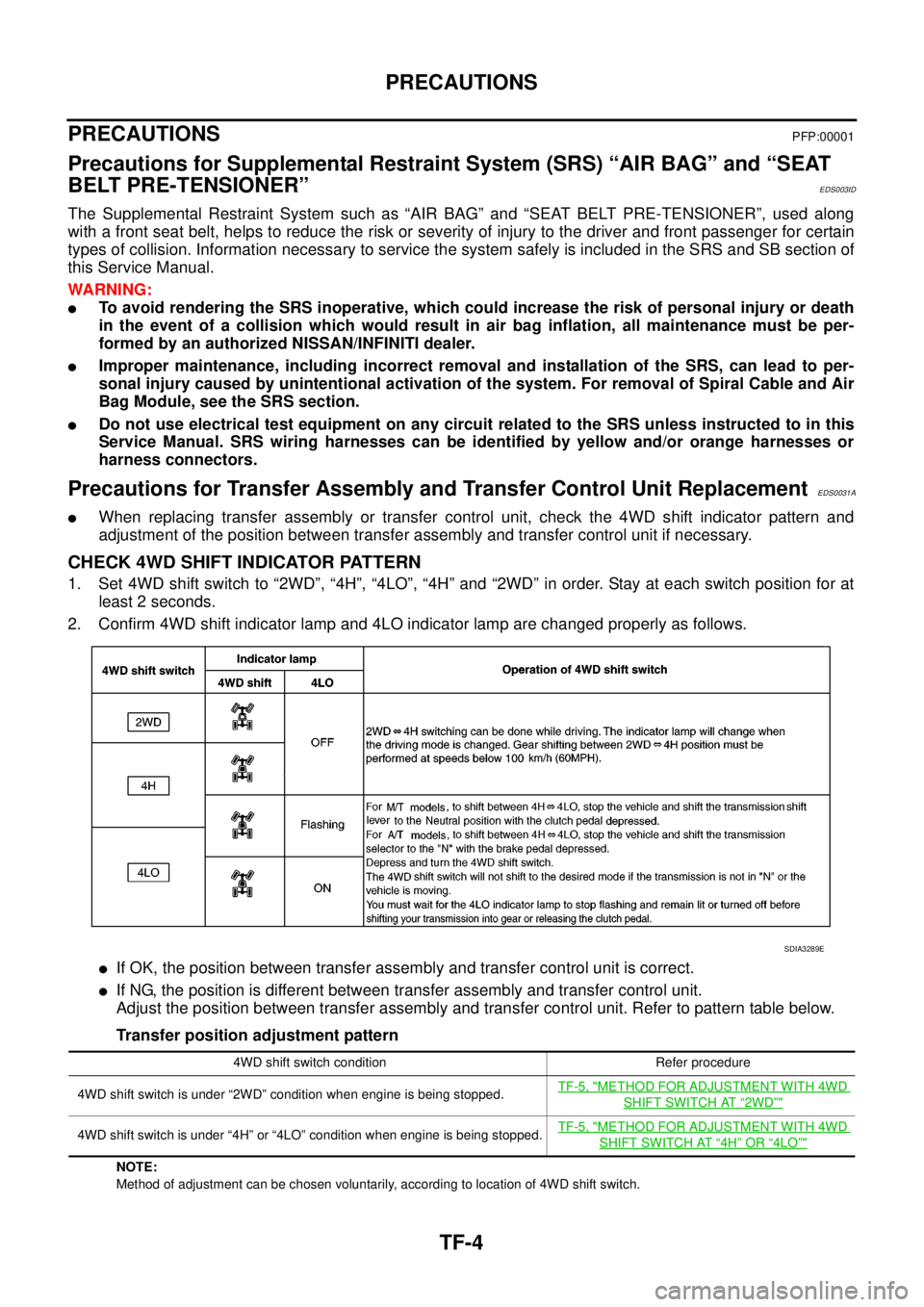
1. Set 4WD shift switch to “2WD”, “4H”, “4LO”, “4H” and “2WD” in order. Stay at each switch position for at
least 2 seconds.
2. Confirm 4WD shift indicator lamp and 4LO indicator lamp are changed properly as follows.
lIf OK, the position between transfer assembly and transfer control unit is correct.
lIf NG, the position is different between transfer assembly and transfer control unit.
Adjust the position between transfer assembly and transfer control unit. Refer to pattern table below.
Transfer position adjustment pattern
NOTE:
Method of adjustment can be chosen voluntarily, according to location of 4WD shift switch.
SDIA3289E
4WD shift switch condition Refer procedure
4WD shift switch is under “2WD” condition when engine is being stopped.TF-5, "
METHOD FOR ADJUSTMENT WITH 4WD
SHIFT SWITCH AT“2WD”"
4WD shift switch is under “4H” or “4LO” condition when engine is being stopped.TF-5, "METHOD FOR ADJUSTMENT WITH 4WD
SHIFT SWITCH AT“4H”OR“4LO”"