2005 NISSAN NAVARA 4WD
[x] Cancel search: 4WDPage 9 of 3171

AT-1
AUTOMATIC TRANSMISSION
C TRANSMISSION/TRANSAXLE
CONTENTS
D
E
F
G
H
I
J
K
L
M
SECTIONAT
A
B
AT
AUTOMATIC TRANSMISSION
INDEX FOR DTC ........................................................ 5
Alphabetical Index .................................................... 5
DTC No. Index ......................................................... 6
PRECAUTIONS .......................................................... 7
Precautions for Supplemental Restraint System
(SRS)“AIRBAG”and“SEATBELTPRE-TEN-
SIONER” .................................................................. 7
Precautions .............................................................. 7
Wiring Diagrams and Trouble Diagnosis .................. 8
PREPARATION ........................................................... 9
Special Service Tools ............................................... 9
Commercial Service Tools ...................................... 10
A/T FLUID ..................................................................11
Changing A/T Fluid ................................................. 11
Checking A/T Fluid ................................................. 12
A/T CONTROL SYSTEM .......................................... 14
Cross-Sectional View (2WD Models) ..................... 14
Cross-Sectional View (4WD Models) ..................... 15
Shift Mechanism ..................................................... 16
TCM Function ......................................................... 27
CAN Communication .............................................. 28
Input/Output Signal of TCM .................................... 28
Line Pressure Control ............................................ 29
Shift Control ........................................................... 30
Lock-up Control ...................................................... 31
Engine Brake Control ............................................. 32
Control Valve .......................................................... 33
TROUBLE DIAGNOSIS ............................................ 34
DTC Inspection Priority Chart ................................ 34
Fail-safe ................................................................. 34
How to Perform Trouble Diagnosis for Quick and
Accurate Repair ..................................................... 36
A/T Electrical Parts Location .................................. 41
Circuit Diagram ...................................................... 42
Inspections Before Trouble Diagnosis .................... 43
Check Before Engine Is Started ............................. 46
Check at Idle .......................................................... 47
Cruise Test - Part 1 ................................................ 48
Cruise Test - Part 2 ................................................ 50
Cruise Test - Part 3 ................................................ 51Vehicle Speed at Which Gear Shifting Occurs ....... 52
Vehicle Speed at Which Lock-up Occurs/Releases... 52
Symptom Chart ....................................................... 53
TCM Input/Output Signal Reference Values ........... 76
CONSULT-II Function (A/T) .................................... 77
Diagnostic Procedure Without CONSULT-II ........... 89
DTC U1000 CAN COMMUNICATION LINE .............. 91
Description .............................................................. 91
On Board Diagnosis Logic ...................................... 91
Possible Cause ....................................................... 91
DTC Confirmation Procedure ................................. 91
Wiring Diagram — AT — CAN ................................ 92
Diagnostic Procedure ............................................. 93
DTC P0615 START SIGNAL CIRCUIT ..................... 94
Description .............................................................. 94
CONSULT-II Reference Value ................................ 94
On Board Diagnosis Logic ...................................... 94
Possible Cause ....................................................... 94
DTC Confirmation Procedure ................................. 94
Wiring Diagram — AT — STSIG ............................ 95
Diagnostic Procedure ............................................. 96
DTC P0700 TCM ....................................................... 98
Description .............................................................. 98
On Board Diagnosis Logic ...................................... 98
Possible Cause ....................................................... 98
DTC Confirmation Procedure ................................. 98
Diagnostic Procedure ............................................. 98
DTC P0705 PARK/NEUTRAL POSITION SWITCH... 99
Description .............................................................. 99
CONSULT-II Reference Value ................................ 99
On Board Diagnosis Logic ...................................... 99
Possible Cause ....................................................... 99
DTC Confirmation Procedure ................................. 99
Wiring Diagram — AT — PNP/SW .......................100
Diagnostic Procedure ...........................................101
DTC P0720 VEHICLE SPEED SENSOR A/T (REV-
OLUTION SENSOR) ...............................................103
Description ............................................................103
CONSULT-II Reference Value ..............................103
On Board Diagnosis Logic ....................................103
Page 18 of 3171
AT-10
PREPARATION
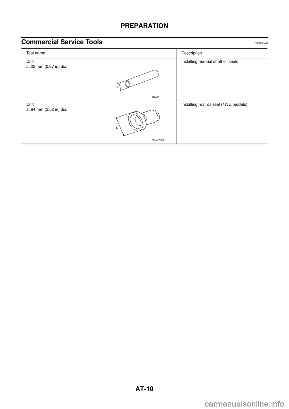
Commercial Service Tools
ECS00FWC
Tool nameDescription
Drift
a: 22 mm (0.87 in) dia.Installing manual shaft oil seals
Drift
a: 64 mm (2.52 in) dia.Installing rear oil seal (4WD models)
NT083
SCIA5338E
Page 23 of 3171
A/T CONTROL SYSTEM
AT-15
D
E
F
G
H
I
J
K
L
MA
B
AT
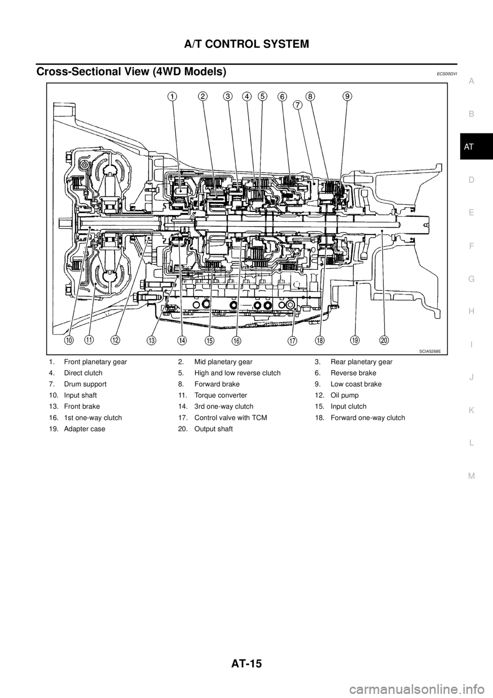
Cross-Sectional View (4WD Models)ECS00GVI
1. Front planetary gear 2. Mid planetary gear 3. Rear planetary gear
4. Direct clutch 5. High and low reverse clutch 6. Reverse brake
7. Drum support 8. Forward brake 9. Low coast brake
10. Input shaft 11. Torque converter 12. Oil pump
13. Front brake 14. 3rd one-way clutch 15. Input clutch
16. 1st one-way clutch 17. Control valve with TCM 18. Forward one-way clutch
19. Adapter case 20. Output shaft
SCIA5268E
Page 60 of 3171

AT-52
TROUBLE DIAGNOSIS
Vehicle Speed at Which Gear Shifting Occurs
ECS00FX6
2WD MODELS
lAt half throttle, the accelerator opening is 4/8 of the full opening.
4WD MODELS
lAt half throttle, the accelerator opening is 4/8 of the full opening.
Vehicle Speed at Which Lock-up Occurs/ReleasesECS00FX7
2WD MODELS
lAt closed throttle, the accelerator opening is less than 1/8 condition. (Closed throttle position signal: OFF)
lAt half throttle, the accelerator opening is 4/8 of the full opening.
4WD MODELS
lAt closed throttle, the accelerator opening is less than 1/8 condition. (Closed throttle position signal: OFF)
lAt half throttle, the accelerator opening is 4/8 of the full opening.Tire sizeThrottle
positionVehicle speed [km/h (MPH)]
D
1®D2D2®D3D3®D4D4®D5D5®D4D4®D3D3®D2D2®D1
255/65 R17
255/70 R16Full
throttle41 - 45
(25 - 28)66 - 72
(41 - 45)103 - 113
(64 - 70)148 - 164
(92 - 102)144 - 160
(89 - 99)92 - 102
(57 - 63)53 - 59
(33 - 37)23 - 24
(14 - 15)
Half
throttle34 - 38
(21 - 24)55 - 61
(34 - 38)86 - 96
(53 - 60)118 - 130
(73 - 81)88 - 98
(55 - 61)60 - 66
(37 - 41)39 - 43
(24 - 27)10 - 11
(6 - 7)
Tire sizeThrottle
positionVehiclespeed [km/h(MPH)]
D1®D2D2®D3D3®D4D4®D5D5®D4D4®D3D3®D2D2®D1
255/65 R17
255/70 R16Full
throttle38 - 42
(24 - 26)62 - 68
(39 - 42)97 - 107
(60 - 66)141 - 155
(88 - 96)137 - 151
(85 - 94)87 - 97
(54 - 60)50 - 56
(31 - 35)22 - 24
(14 - 15)
Half
throttle32 - 36
(20 - 22)52 - 58
(32 - 36)82 - 90
(51 - 56)117 - 129
(73 - 80)83 - 91
(52 - 57)57 - 63
(35 - 39)37 - 41
(23 - 25)10 - 11
(6 - 7)
265/70 R16LTFull
throttle40 - 44
(25 - 27)65 - 71
(40 - 44)101 - 111
(63 - 69)145 - 161
(90 - 100)142 - 156
(88 - 97)90 - 100
(56 - 62)52 - 58
(32 - 36)23 - 25
(14 - 16)
Half
throttle33 - 37
(21 - 23)54 - 60
(34 - 37)85 - 93
(53 - 58)121 - 133
(75 - 83)85 - 95
(53 - 59)59 - 65
(37 - 40)38 - 42
(24 - 26)10 - 11
(6 - 7)
Tire size Throttle positionVehicle speed [km/h (MPH)]
Lock-up ON Lock-up OFF
255/65 R17
255/70 R16Closed throttle 73 - 81 (45 - 50) 70 - 78 (44 - 48)
Half throttle 141 - 155 (88 - 96) 130 - 144 (81 - 89)
Tire size Throttle positionVehicle speed [km/h (MPH)]
Lock-up ON Lock-up OFF
255/65 R17
255/70 R16Closed throttle 69 - 77 (43 - 48) 66 - 74 (41 - 46)
Half throttle 134 - 148 (83 - 92) 123 - 137 (76 - 85)
265/70 R16LTClosed throttle 72 - 80 (45 - 50) 69 - 77 (43 - 48)
Half throttle 139 - 153 (86 - 95) 128 - 142 (80 - 88)
Page 61 of 3171
TROUBLE DIAGNOSIS
AT-53
D
E
F
G
H
I
J
K
L
MA
B
AT
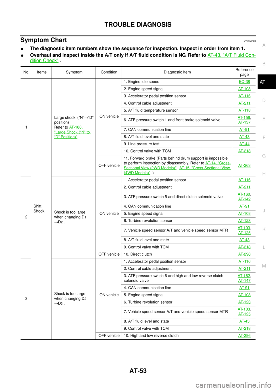
Symptom ChartECS00FX8
lThe diagnostic item numbers show the sequence for inspection. Inspect in order from item 1.
lOverhaul and inspect inside the A/T only if A/T fluid condition is NG. Refer toAT-43, "A/T Fluid Con-
dition Check".
No. Items Symptom Condition Diagnostic ItemReference
page
1
Shift
ShockLarge shock. (“N”®“D”
position)
Refer toAT-180,
"Large Shock (“N”to
“D”Position)".ON vehicle1. Engine idle speedEC-38
2. Engine speed signalAT-108
3. Accelerator pedal position sensorAT- 11 6
4. Control cable adjustmentAT- 2 11
5. A/T fluid temperature sensorAT- 11 8
6. ATF pressure switch 1 and front brake solenoid valveAT-156,
AT-137
7. CAN communication lineAT- 9 1
8. A/T fluid level and stateAT- 4 3
9. Line pressure testAT- 4 4
10. Control valve with TCMAT-218
OFF vehicle11. Forward brake (Parts behind drum support is impossible
to perform inspection by disassembly. Refer toAT- 1 4 , "Cross-
Sectional View (2WD Models)",AT- 1 5 , "Cross-Sectional View
(4WD Models)".)AT-263
2Shock is too large
when changing D1
®D2.ON vehicle1. Accelerator pedal position sensorAT- 11 6
2. Control cable adjustmentAT- 2 11
3. ATF pressure switch 5 and direct clutch solenoid valveAT-160,
AT-142
4. CAN communication lineAT- 9 1
5. Engine speed signalAT-108
6. Turbine revolution sensorAT-123
7. Vehicle speed sensor A/T and vehicle speed sensor MTRAT-103,
AT-125
8. A/T fluid level and stateAT- 4 3
9. Control valve with TCMAT-218
OFF vehicle 10. Direct clutchAT-298
3Shock is too large
when changing D2
®D3.ON vehicle1. Accelerator pedal position sensorAT- 11 6
2. Control cable adjustmentAT- 2 11
3. ATF pressure switch 6 and high and low reverse clutch
solenoid valveAT-162,
AT-147
4. CAN communication lineAT- 9 1
5. Engine speed signalAT-108
6. Turbine revolution sensorAT-123
7. Vehicle speed sensor A/T and vehicle speed sensor MTRAT-103,
AT-125
8. A/T fluid level and stateAT- 4 3
9. Control valve with TCMAT-218
OFF vehicle 10. High and low reverse clutchAT-296
Page 66 of 3171
AT-58
TROUBLE DIAGNOSIS
18
Slips/Will
Not
EngageWhen “D” position,
remains in 1st gear.ON vehicle1. A/T fluid level and stateAT- 4 3
2. Vehicle speed sensor A/T and vehicle speed sensor MTRAT- 1 0 3,
AT- 1 2 5
3. Direct clutch solenoid valveAT- 1 4 2
4. Line pressure testAT- 4 4
5. CAN communication lineAT- 9 1
6. Control valve with TCMAT- 2 1 8
OFF vehicle7. 3rd one-way clutchAT- 2 8 4
8. 1st one-way clutchAT- 2 9 1
9. Gear systemAT- 2 5 1
10. Reverse brakeAT- 2 6 3
11. Forward one-way clutch (Parts behind drum support is
impossible to perform inspection by disassembly. Refer toAT-
14, "Cross-Sectional View (2WD Models)",AT- 1 5 , "Cross-
Sectional View (4WD Models)".)AT- 2 6 3
12. Forward brake (Parts behind drum support is impossible
to perform inspection by disassembly. Refer toAT-14, "
Cross-
Sectional View (2WD Models)",AT-15, "Cross-Sectional View
(4WD Models)".)AT- 2 6 3
19When “D” position,
remains in 2nd gear.ON vehicle1. A/T fluid level and stateAT- 4 3
2. Vehicle speed sensor A/T and vehicle speed sensor MTRAT- 1 0 3,
AT- 1 2 5
3. Low coast brake solenoid valveAT- 1 5 2
4. Line pressure testAT- 4 4
5. CAN communication lineAT- 9 1
6. Control valve with TCMAT- 2 1 8
OFF vehicle7. 3rd one-way clutchAT- 2 8 4
8. Gear systemAT- 2 5 1
9. Direct clutchAT- 2 9 8
10. Forward brake (Parts behind drum support is impossible
to perform inspection by disassembly. Refer toAT-14, "
Cross-
Sectional View (2WD Models)",AT-15, "Cross-Sectional View
(4WD Models)".)AT- 2 6 3
No. Items Symptom Condition Diagnostic ItemReference
page
Page 67 of 3171
TROUBLE DIAGNOSIS
AT-59
D
E
F
G
H
I
J
K
L
MA
B
AT
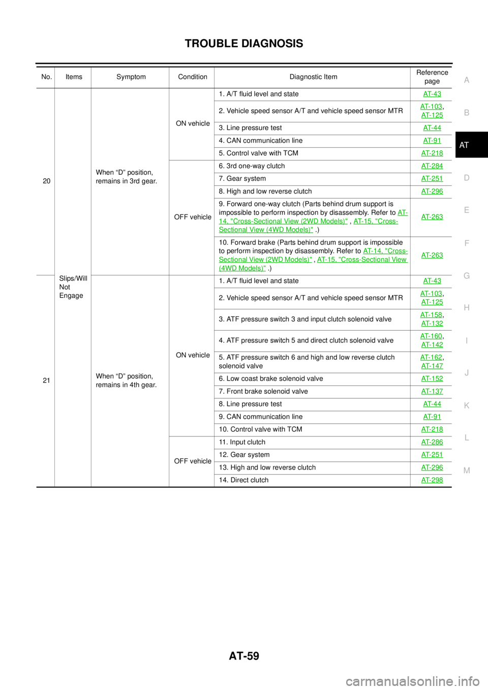
20
Slips/Will
Not
EngageWhen “D” position,
remains in 3rd gear.ON vehicle1. A/T fluid level and stateAT- 4 3
2. Vehicle speed sensor A/T and vehicle speed sensor MTRAT-103,
AT-125
3. Line pressure testAT- 4 4
4. CAN communication lineAT- 9 1
5. Control valve with TCMAT-218
OFF vehicle6. 3rd one-way clutchAT-284
7. Gear systemAT-251
8. High and low reverse clutchAT-296
9. Forward one-way clutch (Parts behind drum support is
impossible to perform inspection by disassembly. Refer toAT-
14, "Cross-Sectional View (2WD Models)",AT- 1 5 , "Cross-
SectionalView(4WDModels)".)AT-263
10. Forward brake (Parts behind drum support is impossible
to perform inspection by disassembly. Refer toAT- 1 4 , "
Cross-
Sectional View (2WD Models)",AT- 1 5 , "Cross-Sectional View
(4WD Models)".)AT-263
21When “D” position,
remains in 4th gear.ON vehicle1. A/T fluid level and stateAT- 4 3
2. Vehicle speed sensor A/T and vehicle speed sensor MTRAT-103,
AT-125
3. ATF pressure switch 3 and input clutch solenoid valveAT-158,
AT-132
4. ATF pressure switch 5 and direct clutch solenoid valveAT-160,
AT-142
5. ATF pressure switch 6 and high and low reverse clutch
solenoid valveAT-162,
AT-147
6. Low coast brake solenoid valveAT-152
7. Front brake solenoid valveAT-137
8. Line pressure testAT- 4 4
9. CAN communication lineAT- 9 1
10. Control valve with TCMAT-218
OFF vehicle11. Input clutchAT-28612. Gear systemAT-251
13. High and low reverse clutchAT-296
14. Direct clutchAT-298
No. Items Symptom Condition Diagnostic ItemReference
page
Page 68 of 3171
AT-60
TROUBLE DIAGNOSIS
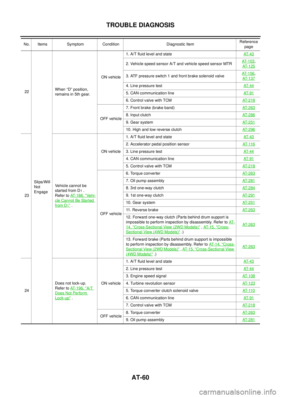
22
Slips/Will
Not
EngageWhen “D” position,
remains in 5th gear.ON vehicle1. A/T fluid level and stateAT- 4 3
2. Vehicle speed sensor A/T and vehicle speed sensor MTRAT- 1 0 3,
AT- 1 2 5
3. ATF pressure switch 1 and front brake solenoid valveAT- 1 5 6,
AT- 1 3 7
4. Line pressure testAT- 4 4
5. CAN communication lineAT- 9 1
6. Control valve with TCMAT- 2 1 8
OFF vehicle7. Front brake (brake band)AT- 2 6 38. Input clutchAT- 2 8 6
9. Gear systemAT- 2 5 1
10. High and low reverse clutchAT- 2 9 6
23Vehicle cannot be
started from D
1.
Refer toAT-186, "
Vehi-
cle Cannot Be Started
from D1".ON vehicle1. A/T fluid level and stateAT- 4 3
2. Accelerator pedal position sensorAT- 11 6
3. Line pressure testAT- 4 4
4. CAN communication lineAT- 9 1
5. Control valve with TCMAT- 2 1 8
OFF vehicle6. Torque converterAT- 2 6 3
7. Oil pump assemblyAT- 2 8 1
8. 3rd one-way clutchAT- 2 8 4
9. 1st one-way clutchAT- 2 9 1
10. Gear systemAT- 2 5 1
11. Reverse brakeAT- 2 6 3
12. Forward one-way clutch (Parts behind drum support is
impossible to perform inspection by disassembly. Refer toAT-
14, "Cross-Sectional View (2WD Models)",AT- 1 5 , "Cross-
Sectional View (4WD Models)".)AT- 2 6 3
13. Forward brake (Parts behind drum support is impossible
to perform inspection by disassembly. Refer toAT-14, "
Cross-
Sectional View (2WD Models)",AT-15, "Cross-Sectional View
(4WD Models)".)AT- 2 6 3
24Does not lock-up.
Refer toAT-196, "A/T
Does Not Perform
Lock-up".ON vehicle1. A/T fluid level and stateAT- 4 3
2. Line pressure testAT- 4 4
3. Engine speed signalAT- 1 0 8
4. Turbine revolution sensorAT- 1 2 3
5. Torque converter clutch solenoid valveAT- 11 0
6. CAN communication lineAT- 9 1
7. Control valve with TCMAT- 2 1 8
OFF vehicle8. Torque converterAT- 2 6 39. Oil pump assemblyAT- 2 8 1
No. Items Symptom Condition Diagnostic ItemReference
page