2005 NISSAN NAVARA key battery
[x] Cancel search: key batteryPage 222 of 3171

AT-214
A/T SHIFT LOCK SYSTEM
Diagnostic Procedure
ECS00G32
SYMPTOM 1:
lSelector lever cannot be moved from “P” position with key in ON position and brake pedal
applied.
lSelector lever can be moved from “P” position with key in ON position and brake pedal released.
lSelector lever can be moved from “P” position when key is removed from key cylinder.
SYMPTOM 2:
lIgnition key cannot be removed when selector lever is set to “P” position.
lIgnition key can be removed when selector lever is set to any position except “P” position.
1.CHECK KEY INTERLOCK CABLE
Check key interlock cable for damage.
OK or NG
OK >> GO TO 2.
NG >> Repair or replace key interlock cable. Refer toAT- 2 1 6 , "
Removal and Installation".
2.CHECK SELECTOR LEVER POSITION
Check selector lever position for damage. Refer toAT- 2 11 , "
Checking of A/T Position"
OK or NG
OK >> GO TO 3.
NG >> Adjust control cable. Refer toAT- 2 11 , "
Adjustment of A/T Position".
3.CHECK SHIFT LOCK SOLENOID AND PARK POSITION SWITCH
1. Connect A/T device harness connector.
2. Turn ignition switch ON. (Do not start engine.)
3. Selector lever is set in “P” position.
4. Check operation.
OK or NG
OK >>INSPECTION END
NG >> GO TO 4.
4.CHECK POWER SOURCE
1. Turn ignition switch ON. (Do not start engine.)
2. Check voltage between A/T device harness connector M79 ter-
minal 1 and ground.
OK or NG
OK >> GO TO 7.
NG >> GO TO 5.
Condition Brake pedal Operation
When ignition switch is turned to ON and selector lever is
set in “P” position.Depressed Yes
Released No
Condition Brake pedal Data (Approx.)
When ignition switch is turned to ON.Depressed Battery voltage
Released 0V
SCIA2122E
Page 575 of 3171

BCM (BODY CONTROL MODULE)
BCS-9
C
D
E
F
G
H
I
J
L
MA
B
BCS
MAJOR COMPONENTS AND CONTROL SYSTEM
CAN Communication System DescriptionEKS00PA2
Refer toLAN-23, "CAN COMMUNICATION".
System Input Output
Remote keyless entry system Keyfob
lAll-door locking actuator
lTurn signal lamp (LH, RH)
lCombination meter (Turn signal
lamp)
Power door lock system Door lock/unlock switch All-door locking actuator
Power supply (IGN) to power win-
dow and sunroofIgnition power supply Power window and sunroof system
Power supply (BAT) to power
window and sunroofBattery power supply Power window and sunroof system
Headlamp Combination switch IPDM E/R
Tail lamp Combination switch IPDM E/R
Front fog lamp Combination switch IPDM E/R
Rear fog lamp Combination switch
lRear fog lamp
lCombination meter
Turn signal lamp Combination switch
lTurn signal lamp
lCombination meter
Hazard lamp Hazard switch
lTurn signal lamp
lCombination meter
Room lamp timer
lKey switch
lKeyfob
lDoor lock/unlock switch
lFront door switch driver side
lAll-door switchInterior room lamp
Light warning chime
lCombination switch
lKey switch
lFront door switch driver sideCombination meter (warning buzzer)
Rain-sensing intermittent wiper
lCombination switch
lLight and rain sensorIPDM E/R
Vehicle-speed-sensing intermit-
tent wiper
lCombination switch
lCombination meterIPDM E/R
Headlamp washer Combination switch IPDM E/R
Rear window defogger
lRear window defogger switch
lIgnition switch (ACC, ON)IPDM E/R
A/C switch signal Front air control ECM
Blower fan switch signal Front air control ECM
Page 583 of 3171

BCM (BODY CONTROL MODULE)
BCS-17
C
D
E
F
G
H
I
J
L
MA
B
BCS
ConfigurationEKS00PA6
Refer toGI-37, "Configuration (BCM)".
Removal and Installation of BCMEKS00PA7
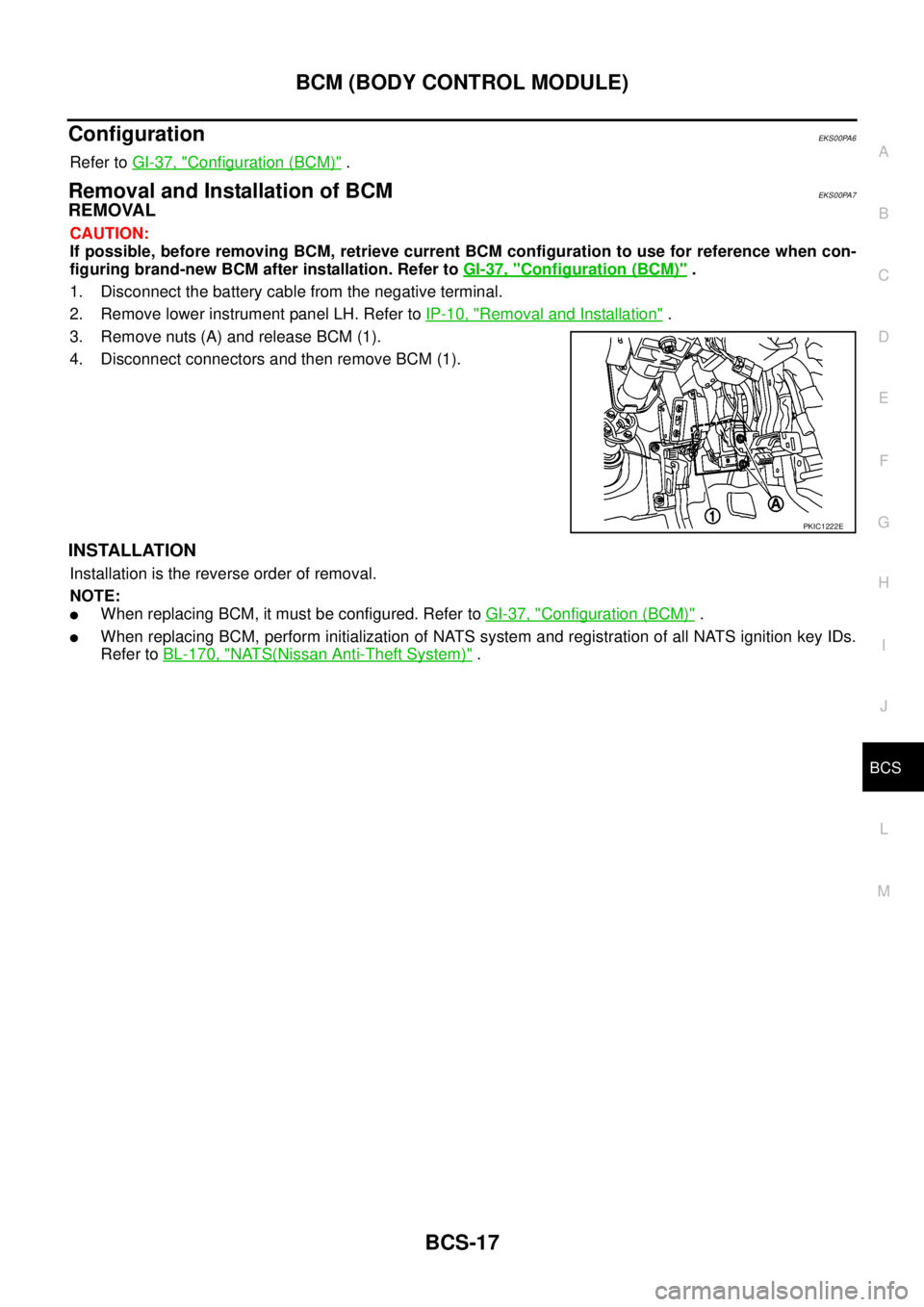
REMOVAL
CAUTION:
If possible, before removing BCM, retrieve current BCM configuration to use for reference when con-
figuring brand-new BCM after installation. Refer toGI-37, "
Configuration (BCM)".
1. Disconnect the battery cable from the negative terminal.
2. Remove lower instrument panel LH. Refer toIP-10, "
Removal and Installation".
3. Remove nuts (A) and release BCM (1).
4. Disconnect connectors and then remove BCM (1).
INSTALLATION
Installation is the reverse order of removal.
NOTE:
lWhen replacing BCM, it must be configured. Refer toGI-37, "Configuration (BCM)".
lWhen replacing BCM, perform initialization of NATS system and registration of all NATS ignition key IDs.
Refer toBL-170, "
NATS(Nissan Anti-Theft System)".
PKIC1222E
Page 586 of 3171

BL-2
Model) ..................................................................... 51
Check RH and LH Rear Door Lock Actuator Switch... 51
Check Door Lock/Unlock Switch ............................ 52
Check Door Lock/Unlock Switch Indicator .............. 53
POWER DOOR LOCK — SUPER LOCK — ............ 55
Component Parts and Harness Connector Location... 55
KING CAB ........................................................... 55
DOUBLE CAB ..................................................... 56
System Description ................................................. 57
OUTLINE ............................................................. 58
OPERATION ........................................................ 58
CAN Communication System Description .............. 59
CAN Communication Unit ....................................... 59
Schematic ............................................................... 60
Wiring Diagram —D/LOCK— ................................. 61
Terminals and Reference Value for BCM ................ 69
CONSULT-II Function (BCM) .................................. 70
CONSULT-II BASIC OPERATION PROCEDURE
... 70
CONSULT-II APPLICATION ITEMS .................... 71
Work Flow ............................................................... 72
Trouble Diagnoses Chart by Symptom ................... 72
Check Power Supply and Ground Circuit ............... 73
Check Door Switch ................................................. 74
CHECK DOOR SWITCH (DOUBLE CAB) .......... 74
CHECK DOOR SWITCH (KING CAB) ................ 76
Check Key Switch ................................................... 78
Check Front Door Lock Actuator (Driver Side) ....... 80
Check Front Door Lock Actuator (Passenger Side)... 81
Check Front Door Lock Actuator Switch ................. 81
Check Rear Door Lock Actuator LH (Double Cab
Models) ................................................................... 82
Check Rear Door Lock Actuator RH (Double Cab
Models) ................................................................... 82
Check RH and LH Rear Door Lock Actuator Switch
(Double Cab Models) .............................................. 83
Check Super Lock Actuator (Driver Side) ............... 83
Check Super Lock Actuator (Passenger Side) ....... 84
Check Super Lock Actuator (Rear LH) ................... 84
Check Super Lock Actuator (Rear RH) .................. 85
Check Door Lock/Unlock Switch ............................ 86
Check Door Lock/Unlock Switch Indicator .............. 87
MULTI-REMOTE CONTROL SYSTEM ..................... 89
Component Parts and Harness Connector Location... 89
KING CAB ........................................................... 89
DOUBLE CAB ..................................................... 90
System Description ................................................. 91
INPUTS ............................................................... 91
OPERATING PROCEDURE ................................ 91
CAN Communication System Description .............. 92
Wiring Diagram — MULTI — For LHD Models ....... 93
Wiring Diagram — MULTI — For RHD Models ...... 97
Terminals and Reference Value for BCM ..............101
CONSULT-II Function (BCM) ................................102
CONSULT-II Inspection Procedure .......................102
“MULTI REMOTE ENT” .....................................102
CONSULT-II Application Items .............................103
“MULTI REMOTE ENT” .....................................103
Trouble Diagnosis Procedure ...............................104Trouble Diagnosis Chart by Symptom ..................105
Check Keyfob Battery and Function .....................106
Check ACC Switch ................................................107
Check Door Switch ...............................................108
CHECK DOOR SWITCH (DOUBLE CAB) .........108
CHECK DOOR SWITCH (KING CAB) ...............110
Check Key Switch .................................................113
Check Hazard Function ........................................114
Check Map Lamp and Ignition Keyhole Illumination
Function ................................................................114
ID Code Entry Procedure ......................................115
KEYFOB ID SET UP ..........................................115
CONSULT-II INSPECTION PROCEDURE ........115
Remote Controller Battery Replacement ..............116
DOOR ......................................................................117
Fitting Adjustment (King Cab) ...............................117
FRONT DOOR ...................................................118
REAR DOOR .....................................................118
STRIKER ADJUSTMENT ..................................118
Fitting Adjustment (Double Cab) ...........................119
FRONT DOOR ...................................................120
REAR DOOR .....................................................120
STRIKER ADJUSTMENT ..................................120
Removal and Installation of Front Door ................120
REMOVAL ..........................................................120
INSTALLATION ..................................................121
Removal and Installation of Rear Door (King Cab).121
REMOVAL ..........................................................121
INSTALLATION ..................................................122
Removal and Installation of Rear Door (Double Cab)
.123
REMOVAL ..........................................................123
INSTALLATION ..................................................123
Removal and Installation of Door Weather-strip
(King Cab) .............................................................124
REMOVAL ..........................................................124
INSTALLATION ..................................................124
Removal and Installation of Door Weather-strip
(Double Cab) .........................................................125
REMOVAL ..........................................................125
INSTALLATION ..................................................125
FRONT DOOR LOCK ..............................................126
Removal and Installation .......................................126
REMOVAL ..........................................................126
INSTALLATION ..................................................129
REAR DOOR LOCK ................................................130
Removal and Installation of Rear Door Lock (King
Cab) ......................................................................130
REMOVAL ..........................................................130
INSTALLATION ..................................................131
Removal and Installation of Rear Door Lock (Double
Cab) ......................................................................132
REMOVAL ..........................................................132
INSTALLATION ..................................................134
TAIL GATE ...............................................................135
Component Parts Location ...................................135
FUEL FILLER LID OPENER ...................................136
Removal and Installation of Fuel Filler Lid ............136
REMOVAL ..........................................................136
Page 618 of 3171
![NISSAN NAVARA 2005 Repair Workshop Manual BL-34
POWER DOOR LOCK SYSTEM
Terminals and Reference Value for BCM
EIS00D7Z
*: Double cab modelTERMI-
NALWIRE
COLORITEM CONDITIONVOLTAGE [V]
(Approx.)
3 Y Ignition switch Ignition switch ON Battery vo NISSAN NAVARA 2005 Repair Workshop Manual BL-34
POWER DOOR LOCK SYSTEM
Terminals and Reference Value for BCM
EIS00D7Z
*: Double cab modelTERMI-
NALWIRE
COLORITEM CONDITIONVOLTAGE [V]
(Approx.)
3 Y Ignition switch Ignition switch ON Battery vo](/manual-img/5/57362/w960_57362-617.png)
BL-34
POWER DOOR LOCK SYSTEM
Terminals and Reference Value for BCM
EIS00D7Z
*: Double cab modelTERMI-
NALWIRE
COLORITEM CONDITIONVOLTAGE [V]
(Approx.)
3 Y Ignition switch Ignition switch ON Battery voltage
5RKeyswitchKey switch ON Battery voltage
Key switch OFF 0
12 L Rear door switch RH* ON (Door is opened)®OFF (Door is closed) 0®Battery voltage
14 LGFront door switch
(Passenger side)ON (Door is opened)®OFF (Door is closed) 0®Battery voltage
15 SBFront door switch
(Driver side)ON (Door is opened)®OFF (Door is closed) 0®Battery voltage
16 P Rear door switch LH* ON (Door is opened)®OFF (Door is closed) 0®Battery voltage
17 WDoor lock/unlock switch indi-
catorAll door closedLock operation
(Illuminates)Battery voltage
Other than above 0
21 P CAN-L — —
22 L CAN-H — —
32 GR Door lock/unlock switch All door closedUnlock 0
Other than above 5
34 O Door lock/unlock switch All door closedLock 0
Other than above 5
41 YPower switch
(Fuse)— Battery voltage
54 GPassenger and rear door lock
actuators*1 (unlock)Door lock/unlock switch (Free®Lock) 0®Battery voltage®0
55 B Ground — 0
56 V All door lock actuators (lock) Door lock/unlock switch (Free®Lock) 0®Battery voltage®0
57 WPower source
(Fusible link)— Battery voltage
60 GDriver door lock actuator
(unlock)Door lock/unlock switch (Free®Lock) 0®Battery voltage®0
Page 627 of 3171

POWERDOORLOCKSYSTEM
BL-43
C
D
E
F
G
H
J
K
L
MA
B
BL
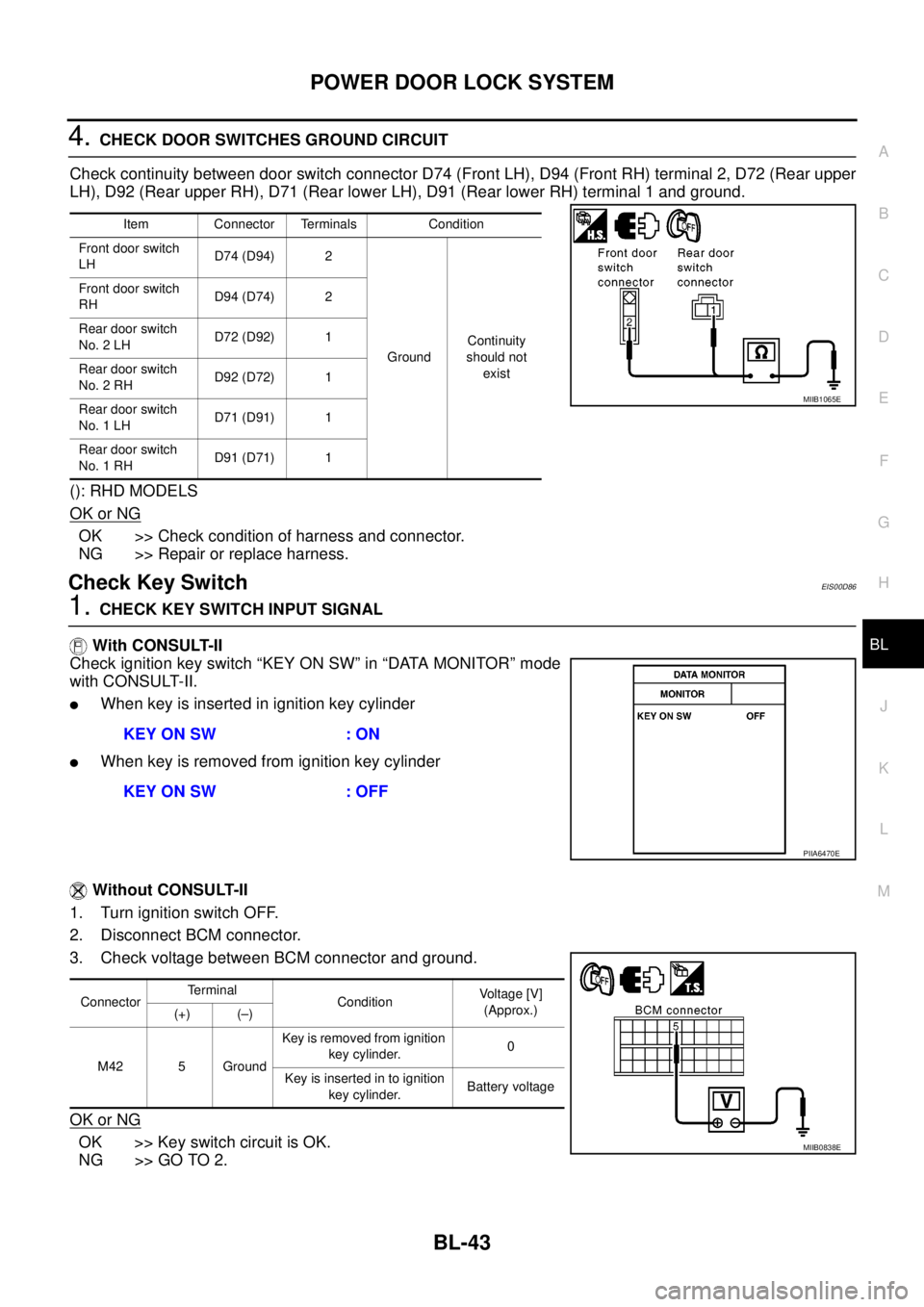
4.CHECK DOOR SWITCHES GROUND CIRCUIT
Check continuity between door switch connector D74 (Front LH), D94 (Front RH) terminal 2, D72 (Rear upper
LH), D92 (Rear upper RH), D71 (Rear lower LH), D91 (Rear lower RH) terminal 1 and ground.
(): RHD MODELS
OK or NG
OK >> Check condition of harness and connector.
NG >> Repair or replace harness.
Check Key SwitchEIS00D86
1.CHECK KEY SWITCH INPUT SIGNAL
With CONSULT-II
Check ignition key switch “KEY ON SW” in “DATA MONITOR” mode
with CONSULT-II.
lWhen key is inserted in ignition key cylinder
lWhen key is removed from ignition key cylinder
Without CONSULT-II
1. Turn ignition switch OFF.
2. Disconnect BCM connector.
3. Check voltage between BCM connector and ground.
OK or NG
OK >> Key switch circuit is OK.
NG >> GO TO 2.
Item Connector Terminals Condition
Front door switch
LHD74 (D94) 2
GroundContinuity
should not
exist Front door switch
RHD94 (D74) 2
Rear door switch
No. 2 LHD72 (D92) 1
Rear door switch
No. 2 RHD92 (D72) 1
Rear door switch
No. 1 LHD71 (D91) 1
Rear door switch
No. 1 RHD91 (D71) 1
MIIB1065E
KEY ON SW : ON
KEY ON SW : OFF
PIIA6470E
ConnectorTerminal
ConditionVoltage [V]
(Approx.)
(+) (–)
M42 5 GroundKey is removed from ignition
key cylinder.0
Keyisinsertedintoignition
key cylinder.Battery voltage
MIIB0838E
Page 653 of 3171
![NISSAN NAVARA 2005 Repair Workshop Manual POWER DOOR LOCK — SUPER LOCK —
BL-69
C
D
E
F
G
H
J
K
L
MA
B
BL
Terminals and Reference Value for BCMEIS00DX5
*: Double cab modelsTERMI-
NALWIRE
COLORITEM CONDITIONVOLTAGE [V]
(Approx.)
3 Y Ignitio NISSAN NAVARA 2005 Repair Workshop Manual POWER DOOR LOCK — SUPER LOCK —
BL-69
C
D
E
F
G
H
J
K
L
MA
B
BL
Terminals and Reference Value for BCMEIS00DX5
*: Double cab modelsTERMI-
NALWIRE
COLORITEM CONDITIONVOLTAGE [V]
(Approx.)
3 Y Ignitio](/manual-img/5/57362/w960_57362-652.png)
POWER DOOR LOCK — SUPER LOCK —
BL-69
C
D
E
F
G
H
J
K
L
MA
B
BL
Terminals and Reference Value for BCMEIS00DX5
*: Double cab modelsTERMI-
NALWIRE
COLORITEM CONDITIONVOLTAGE [V]
(Approx.)
3 Y Ignition switch Ignition switch ON Battery voltage
5 R Key switchKey switch ON Battery voltage
Key switch OFF 0
12 L Rear door switch RH* ON (Door is opened)®OFF (Door is closed) 0®Battery voltage
14 LGFront door switch
(Passenger side)ON (Door is opened)®OFF (Door is closed) 0®Battery voltage
15 SBFront door switch
(Driver side)ON (Door is opened)®OFF (Door is closed) 0®Battery voltage
16 P Rear door switch LH* ON (Door is opened)®OFF (Door is closed) 0®Battery voltage
17 WDoor lock/unlock switch indi-
catorAll door closedLock operation
(Illuminates)Battery voltage
Other than above 0
21 P CAN-L — —
22 L CAN-H — —
32 GR Door lock/unlock switch All door closedUnlock 0
Other than above 5
34 O Door lock/unlock switch All door closedLock 0
Other than above 5
41 Y Power switch (Fuse) — Battery voltage
54 GPassenger and rear door lock
actuators*1 (unlock)Door lock/unlock switch (Free®Lock) 0®Battery voltage®0
55 B Ground — 0
56 V All door lock actuators (lock) Door lock/unlock switch (Free®Lock) 0®Battery voltage®0
57 W Power source (Fusible link) — Battery voltage
59 R Super lock actuator (set)Lock button of key fob or Intelligent Key is
pressed0®Battery voltage®0
60 GDriver door lock actuator
(unlock)Door lock/unlock switch (Free®Lock) 0®Battery voltage®0
Page 662 of 3171

BL-78
POWER DOOR LOCK — SUPER LOCK —
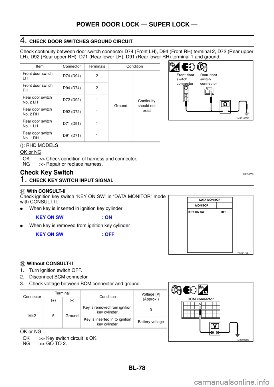
4.CHECK DOOR SWITCHES GROUND CIRCUIT
Check continuity between door switch connector D74 (Front LH), D94 (Front RH) terminal 2, D72 (Rear upper
LH), D92 (Rear upper RH), D71 (Rear lower LH), D91 (Rear lower RH) terminal 1 and ground.
(): RHD MODELS
OK or NG
OK >> Check condition of harness and connector.
NG >> Repair or replace harness.
Check Key SwitchEIS00DXC
1.CHECK KEY SWITCH INPUT SIGNAL
With CONSULT-II
Check ignition key switch “KEY ON SW” in “DATA MONITOR” mode
with CONSULT-II.
lWhen key is inserted in ignition key cylinder
lWhen key is removed from ignition key cylinder
Without CONSULT-II
1. Turn ignition switch OFF.
2. Disconnect BCM connector.
3. Check voltage between BCM connector and ground.
OK or NG
OK >> Key switch circuit is OK.
NG >> GO TO 2.
Item Connector Terminals Condition
Front door switch
LHD74 (D94) 2
GroundContinuity
should not
exist Front door switch
RHD94 (D74) 2
Rear door switch
No. 2 LHD72 (D92) 1
Rear door switch
No. 2 RHD92 (D72) 1
Rear door switch
No. 1 LHD71 (D91) 1
Rear door switch
No. 1 RHD91 (D71) 1
MIIB1065E
KEY ON SW : ON
KEY ON SW : OFF
PIIA6470E
ConnectorTerminal
ConditionVoltage [V]
(Approx.)
(+) (–)
M42 5 GroundKey is removed from ignition
key cylinder.0
Key is inserted in to ignition
key cylinder.Battery voltage
MIIB0838E