2005 NISSAN NAVARA key battery
[x] Cancel search: key batteryPage 1625 of 3171

PRECAUTIONS
GI-3
C
D
E
F
G
H
I
J
K
L
MB
GI
PRECAUTIONSPFP:00001
DescriptionEAS001GG
Observe the following precautions to ensure safe and proper servicing. These precautions are not
described in each individual section.
Precautions for Supplemental Restraint System (SRS) “AIR BAG” and “SEAT
BELT PRE-TENSIONER”
EAS001GH
The Supplemental Restraint System such as “AIR BAG” and “SEAT BELT PRE-TENSIONER”, used along
with a front seat belt, helps to reduce the risk or severity of injury to the driver and front passenger for certain
types of collision. Information necessary to service the system safely is included in the SRS and SB section of
this Service Manual.
WARNING:
lTo avoid rendering the SRS inoperative, which could increase the risk of personal injury or death
in the event of a collision which would result in air bag inflation, all maintenance must be per-
formed by an authorized NISSAN/INFINITI dealer.
lImproper maintenance, including incorrect removal and installation of the SRS, can lead to per-
sonal injury caused by unintentional activation of the system. For removal of Spiral Cable and Air
Bag Module, see the SRS section.
lDo not use electrical test equipment on any circuit related to the SRS unless instructed to in this
Service Manual. SRS wiring harnesses can be identified by yellow and/or orange harnesses or
harness connectors.
Precautions for NATS (NISSAN ANTI-THEFT SYSTEM)EAS001GI
NATS will immobilize the engine if someone tries to start it without the registered key of NATS.
Both of the originally supplied ignition key IDs have been NATS registered.
The security indicator is located on the instrument panel. The indicator blinks when the immobilizer system is
functioning.
Therefore, NATS warns outsiders that the vehicle is equipped with the anti-theft system.
lWhen NATS detects trouble, the security indicator lamp lights up while ignition switch is in "ON" position.
This lighting up indicates that the anti-theft is not functioning, so prompt service is required.
lWhen servicing NATS (trouble diagnoses, system initialization and additional registration of other NATS
ignition key IDs), CONSULT-II hardware and CONSULT-II NATS software is necessary.
Regarding the procedures of NATS initialization and NATS ignition key ID registration, refer to CONSULT-
II operation manual, NATS.
Therefore, CONSULT-II NATS software (program card and operation manual) must be kept strictly con-
fidential to maintain the integrity of the anti-theft function.
lWhen servicing NATS (trouble diagnoses, system initialization and additional registration of other NATS
ignition key IDs), it may be necessary to re-register original key identification. Therefore, be sure to
receive all keys from vehicle owner. A maximum of four or five key IDs can be registered into NATS.
lWhen failing to start the engine first time using the key of NATS, start as follows.
1. Leave the ignition key in "ON" position for approximately 5 seconds.
2. Turn ignition key to "OFF" or "LOCK" position and wait approximately 5 seconds.
3. Repeat step 1 and 2 again.
4. Restart the engine while keeping the key separate from any others on key-chain.
Precautions Necessary for Steering Wheel Rotation After Battery DisconnectEAS001HY
NOTE:
lThis Procedure is applied only to models with Intelligent Key system and NATS (NISSAN ANTI-THEFT
SYSTEM).
lRemove and install all control units after disconnecting both battery cables with the ignition knob in the
²LOCK²position.
lAlways use CONSULT-II to perform self-diagnosis as a part of each function inspection after finishing
work. If DTC is detected, perform trouble diagnosis according to self-diagnostic results.
For models equipped with the Intelligent Key system and NATS, an electrically controlled steering lock mech-
anism is adopted on the key cylinder.
Page 1626 of 3171
GI-4
PRECAUTIONS
For this reason, if the battery is disconnected or if the battery is discharged, the steering wheel will lock and
steering wheel rotation will become impossible.
If steering wheel rotation is required when battery power is interrupted, follow the procedure below before
starting the repair operation.
OPERATION PROCEDURE
1. Connect both battery cables.
NOTE:
Supply power using jumper cables if battery is discharged.
2. Use the Intelligent Key or mechanical key to turn the ignition switch to the²ACC²position. At this time, the
steering lock will be released.
3. Disconnect both battery cables. The steering lock will remain released and the steering wheel can be
rotated.
4. Perform the necessary repair operation.
5. When the repair work is completed, return the ignition switch to the²LOCK²position before connecting
the battery cables. (At this time, the steering lock mechanism will engage.)
6. Perform a self-diagnosis check of all control units using CONSULT-II.
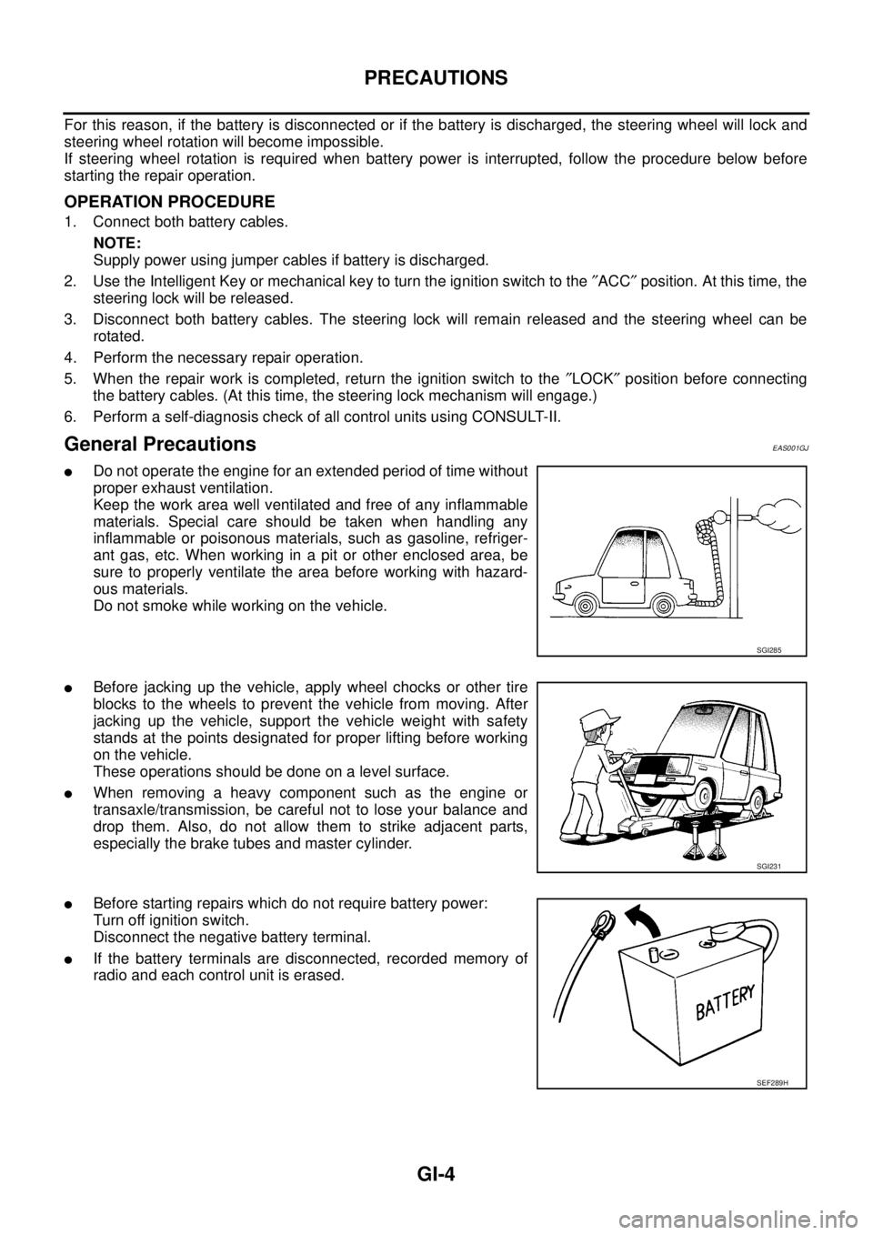
General PrecautionsEAS001GJ
lDo not operate the engine for an extended period of time without
proper exhaust ventilation.
Keep the work area well ventilated and free of any inflammable
materials. Special care should be taken when handling any
inflammable or poisonous materials, such as gasoline, refriger-
ant gas, etc. When working in a pit or other enclosed area, be
sure to properly ventilate the area before working with hazard-
ous materials.
Do not smoke while working on the vehicle.
lBefore jacking up the vehicle, apply wheel chocks or other tire
blocks to the wheels to prevent the vehicle from moving. After
jacking up the vehicle, support the vehicle weight with safety
stands at the points designated for proper lifting before working
on the vehicle.
These operations should be done on a level surface.
lWhen removing a heavy component such as the engine or
transaxle/transmission, be careful not to lose your balance and
drop them. Also, do not allow them to strike adjacent parts,
especially the brake tubes and master cylinder.
lBefore starting repairs which do not require battery power:
Turn off ignition switch.
Disconnect the negative battery terminal.
lIf the battery terminals are disconnected, recorded memory of
radio and each control unit is erased.
SGI285
SGI231
SEF289H
Page 1634 of 3171
GI-12
HOW TO USE THIS MANUAL
3.Symbol used in illustration
Symbols included in illustrations refer to measurements or procedures. Before diagnosing a problem,
familiarize yourself with each symbol. Refer to "Connector Symbols" in GI Section and "KEY TO SYM-
BOLS SIGNIFYING MEASUREMENTS OR PROCEDURES" below.
4.Action items
Next action for each test group is indicated based on result of each question. Test group number is shown
in the left upper portion of each test group.
HARNESS WIRE COLOR AND CONNECTOR NUMBER INDICATION
There are two types of harness wire color and connector number indication.
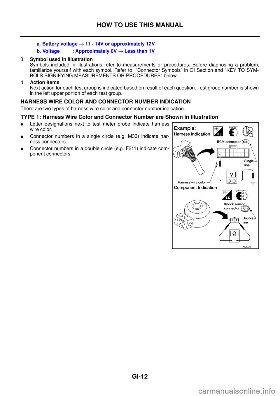
TYPE 1: Harness Wire Color and Connector Number are Shown in Illustration
lLetter designations next to test meter probe indicate harness
wire color.
lConnector numbers in a single circle (e.g. M33) indicate har-
ness connectors.
lConnector numbers in a double circle (e.g. F211) indicate com-
ponent connectors.a. Battery voltage®11 - 14V or approximately 12V
b. Voltage : Approximately 0V®Less than 1V
AGI070
Page 1650 of 3171
GI-28
SERVICE INFORMATION FOR ELECTRICAL INCIDENT
VOLTAGE CHECK METHOD
To help in understanding the diagnosis of open circuits please refer to the previous schematic.
In any powered circuit, an open can be found by methodically checking the system for the presence of voltage.
This is done by switching the DMM to the voltage function.
lConnect one probe of the DMM to a known good ground.
lBegin probing at one end of the circuit and work your way to the other end.
lWith SW1 open, probe at SW1 to check for voltage.
voltage; open is further down the circuit than SW1.
no voltage; open is between fuse block and SW1 (point A).
lClose SW1 and probe at relay.
voltage; open is further down the circuit than the relay.
no voltage; open is between SW1 and relay (point B).
lClose the relay and probe at the solenoid.
voltage; open is further down the circuit than the solenoid.
no voltage; open is between relay and solenoid (point C).
Any powered circuit can be diagnosed using the approach in the previous example.
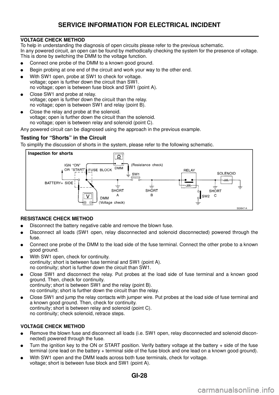
Testing for “Shorts” in the Circuit
To simplify the discussion of shorts in the system, please refer to the following schematic.
RESISTANCE CHECK METHOD
lDisconnect the battery negative cable and remove the blown fuse.
lDisconnect all loads (SW1 open, relay disconnected and solenoid disconnected) powered through the
fuse.
lConnect one probe of the DMM to the load side of the fuse terminal. Connect the other probe to a known
good ground.
lWith SW1 open, check for continuity.
continuity; short is between fuse terminal and SW1 (point A).
no continuity; short is further down the circuit than SW1.
lClose SW1 and disconnect the relay. Put probes at the load side of fuse terminal and a known good
ground. Then, check for continuity.
continuity; short is between SW1 and the relay (point B).
no continuity; short is further down the circuit than the relay.
lClose SW1 and jump the relay contacts with jumper wire. Put probes at the load side of fuse terminal and
a known good ground. Then, check for continuity.
continuity; short is between relay and solenoid (point C).
no continuity; check solenoid, retrace steps.
VOLTAGE CHECK METHOD
lRemove the blown fuse and disconnect all loads (i.e. SW1 open, relay disconnected and solenoid discon-
nected) powered through the fuse.
lTurn the ignition key to the ON or START position. Verify battery voltage at the battery + side of the fuse
terminal (one lead on the battery + terminal side of the fuse block and one lead on a known good ground).
lWith SW1 open and the DMM leads across both fuse terminals, check for voltage.
voltage; short is between fuse block and SW1 (point A).
SGI847-A
Page 1772 of 3171
INSTRUMENT PANEL ASSEMBLY
IP-13
C
D
E
F
G
H
J
K
L
MA
B
IP
LOWER INSTRUMENT PANEL LH
Removal
1. Remove LH front kick plate.
2. Remove lower dash side finisher. Refer toEI-34, "
Removal".
3. Remove front pillar finisher. Refer toEI-35, "
Removal".
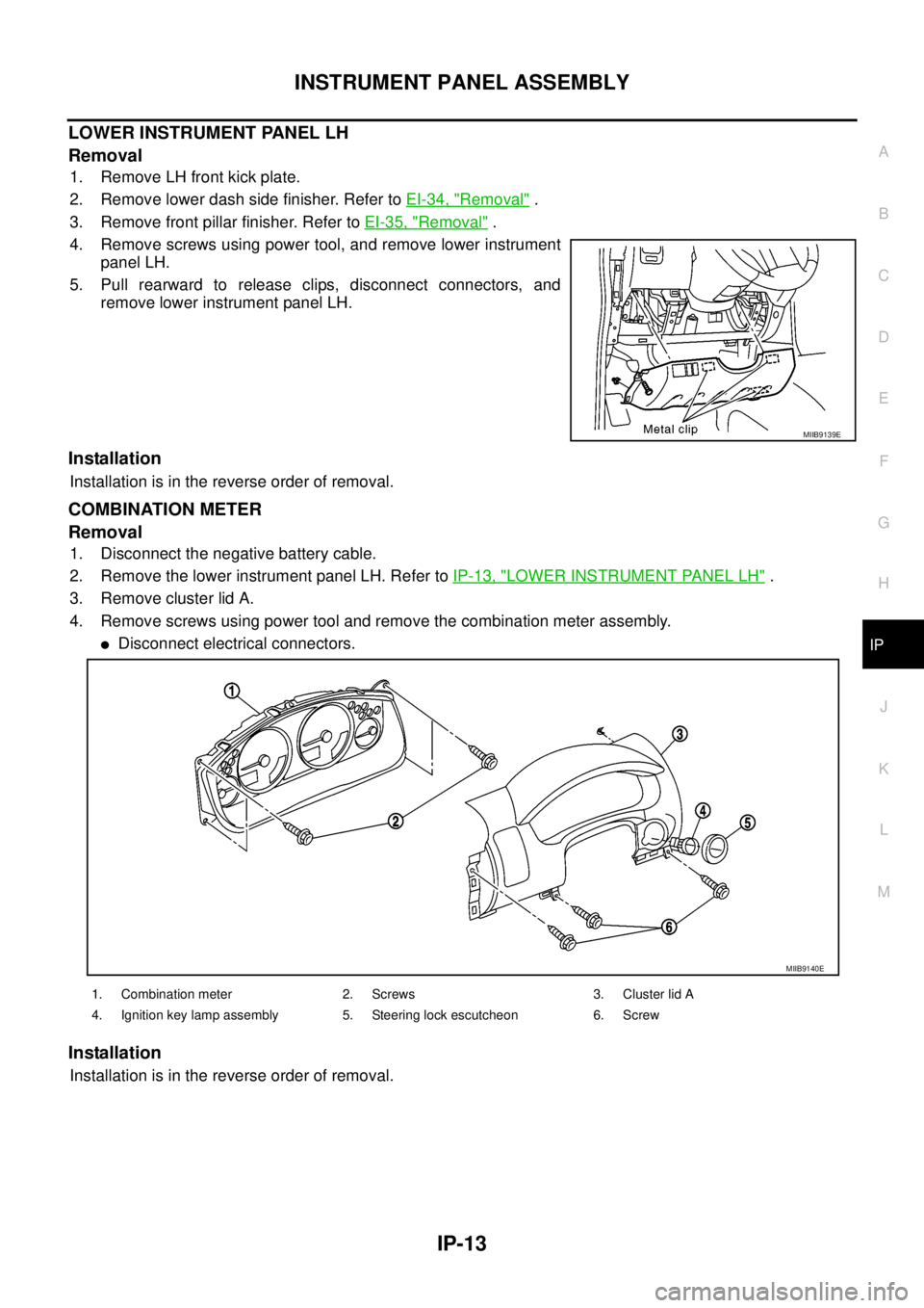
4. Remove screws using power tool, and remove lower instrument
panel LH.
5. Pull rearward to release clips, disconnect connectors, and
remove lower instrument panel LH.
Installation
Installation is in the reverse order of removal.
COMBINATION METER
Removal
1. Disconnect the negative battery cable.
2. Remove the lower instrument panel LH. Refer toIP-13, "
LOWER INSTRUMENT PANEL LH".
3. Remove cluster lid A.
4. Remove screws using power tool and remove the combination meter assembly.
lDisconnect electrical connectors.
Installation
Installation is in the reverse order of removal.
MIIB9139E
1. Combination meter 2. Screws 3. Cluster lid A
4. Ignition key lamp assembly 5. Steering lock escutcheon 6. Screw
MIIB9140E
Page 2230 of 3171

INTERIOR ROOM LAMP
LT-147
C
D
E
F
G
H
I
J
L
MA
B
LT
lthrough rear door switch (passenger side) No.1 and No.2 terminals 2
lthrough grounds B9 and B25 (LHD models)
lthrough grounds B106 and B121 (RHD models).
When a signal is received by BCM, power is supplied
lthrough BCM terminal 42
lto key ring lamp terminal 1
lto front map lamp terminal 1 and
lto room lamp terminal 2.
SWITCH OPERATION
When front map lamp switch is ON, ground is supplied
lto front map lamp terminal 2
lthrough grounds M21, M80 and M83.
When room lamp switch is ON, ground is supplied through room lamp case ground.
ROOM LAMP TIMER OPERATION
When lamp switch is in DOOR position, and when all conditions below are met, BCM performs timer control
(maximum 30 seconds) for interior room lamp and map lamp ON/OFF.
Power is supplied
lthrough 10A fuse [No. 22, located in fuse block (J/B)]
lto key switch terminal 2.
Key is removed from ignition key cylinder (key switch OFF), power will not be supplied to BCM terminal 5.
At the time that driver's door is opened, BCM detects that driver's door is unlocked. It determines that room
lamp timer operation conditions are met, and turns the interior room lamps ON for 30 seconds.
Key is in ignition key cylinder (key switch ON), power is supplied
lthrough key switch terminal 1
lto BCM terminal 5.
When key is removed from key switch (key switch OFF), power supply to BCM terminal 5 is terminated. BCM
detects that key has been removed, determines that room lamp timer conditions are met, and turns the interior
room lamps ON for 30 seconds.
When driver's door opens®closes, and the key is not inserted in the key switch (key switch OFF), BCM ter-
minal 15 changes between 0V (door open)®12V (door closed). The BCM determines that conditions for
room lamp operation are met and turns the room lamp ON for 30 seconds.
Timer control is canceled under the following conditions.
lDriver's door is opened [front door switch (driver side)].
lIgnition switch ON.
lKeyfob
INTERIOR LAMP BATTERY SAVER CONTROL
If interior lamp is left ON, it will not be turned off even when door is closed.
BCM turns off interior lamp automatically to save battery 30 minutes after ignition switch is turned off.
BCM controls interior lamps listed below:
lFront map lamp
lRoom lamp
lKey ring lamp
After lamps turn OFF by the battery saver system, the lamps illuminate again when
lsignal received from keyfob or key cylinder is locked or unlocked,
ldoor is opened or closed,
lkey is removed from ignition key cylinder or inserted in ignition key cylinder.
Interior lamp battery saver control period can be changed by the function setting of CONSULT-II. Refer toLT-
158, "WORK SUPPORT".
Page 2237 of 3171
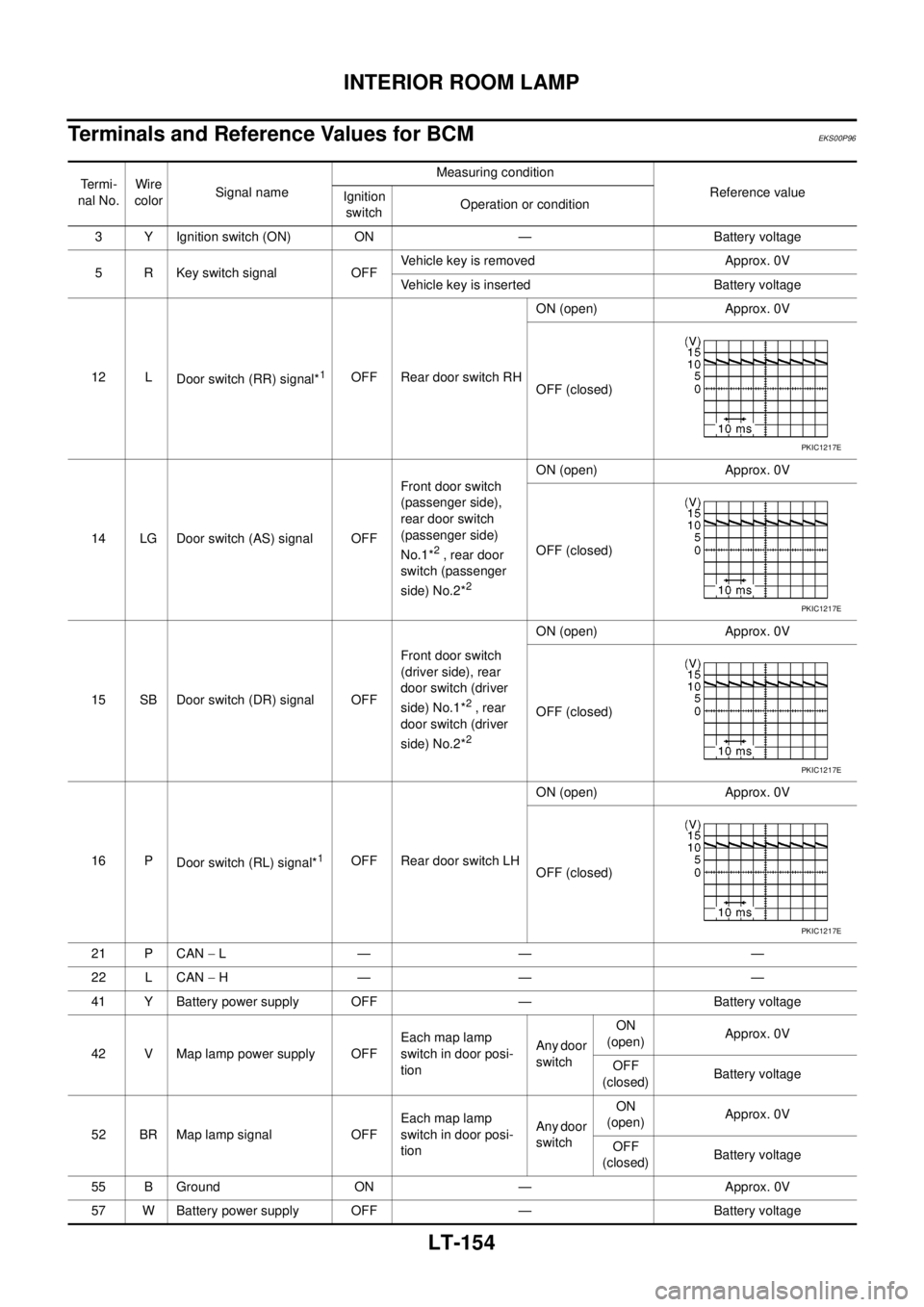
LT-154
INTERIOR ROOM LAMP
Terminals and Reference Values for BCM
EKS00P96
Te r m i -
nal No.Wire
colorSignal nameMeasuring condition
Reference value
Ignition
switchOperation or condition
3 Y Ignition switch (ON) ON — Battery voltage
5 R Key switch signal OFFVehicle key is removed Approx. 0V
Vehicle key is inserted Battery voltage
12 L
Door switch (RR) signal*
1OFF Rear door switch RHON (open) Approx. 0V
OFF (closed)
14 LG Door switch (AS) signal OFFFront door switch
(passenger side),
rear door switch
(passenger side)
No.1*
2, rear door
switch (passenger
side) No.2*
2
ON (open) Approx. 0V
OFF (closed)
15 SB Door switch (DR) signal OFFFront door switch
(driver side), rear
door switch (driver
side) No.1*
2, rear
door switch (driver
side) No.2*
2
ON (open) Approx. 0V
OFF (closed)
16 P
Door switch (RL) signal*
1OFF Rear door switch LHON (open) Approx. 0V
OFF (closed)
21 P CAN-L— — —
22 L CAN-H— — —
41 Y Battery power supply OFF — Battery voltage
42 V Map lamp power supply OFFEach map lamp
switch in door posi-
tionAny door
switchON
(open)Approx. 0V
OFF
(closed)Battery voltage
52 BR Map lamp signal OFFEach map lamp
switch in door posi-
tionAny door
switchON
(open)Approx. 0V
OFF
(closed)Battery voltage
55 B Ground ON — Approx. 0V
57 W Battery power supply OFF — Battery voltage
PKIC1217E
PKIC1217E
PKIC1217E
PKIC1217E
Page 2280 of 3171

DESCRIPTION
MA-5
C
D
E
F
G
H
I
J
K
MA
B
MA
DESCRIPTIONPFP:00000
Pre-Delivery Inspection ItemsELS001K2
Shown below are Pre-delivery Inspection Items required for the new vehicle. It is recommended that
necessary items other than those listed here be added, paying due regard to the conditions in each
country.
Perform applicable items on each model. Consult text of this section for specifications.
Install vehicle protection kit
Fit all accessories ordered (if applicable) (e.g. towbar, audio, navigation, air conditioner, styling kit)
UNDER HOOD — engine off
Check coolant level and cooling system for leaks
Charge battery and check terminals for condition
Check drive belts tension
Check fuel filter for water or dust (diesel only) and fuel system for leaks
Check engine oil level and for oil leaks
Check brake and clutch fluid levels and fluid lines for leaks
Check and top up washer reservoirs
Check power steering fluid level and fluid lines for leaks (if applicable)
Check air conditioning system for gas leaks (if applicable)
ON INSIDE AND OUTSIDE
Install transit fuse if removed for vehicle storage
Check instruments, gauges, lamps, horn and accessories for operation
Check wipers and washers for operation and adjustment
Check interior and door mirrors and sun visors for operation
Set radio code and set clock
Check parking brake adjustment
Check clutch pedal adjustment
Check steering lock operation
Check seat adjusters and seat belts for operation
Check all windows for operation and alignment
Check mouldings, trim and fittings for fit and alignment
Check weatherstrips for fit and adhesion
Check hood, trunk lid, door panels and fuel lid for fit and alignment
Check latches, keys, remote key, door locks and remote trunk lid and fuel lid release for operation
Check wheel nut torques
Check tyre pressure (incl. spare tyre)
Check tool kit and jack for operation
Check automatic transmission/transaxle starter inhibitor (if applicable)
Check sunroof for operation and alignment (if applicable)
UNDER BODY
Check manual transmission/transaxle, differential and transfer box for oil level and oil leaks
Tighten bolts and nuts steering linkage and gear box, axle/suspension parts, propeller and exhaust system
Check brake and clutch lines, and oil/fluid reservoirs for leaks
Remove front suspension spacer blocks (if applicable)
Check body mounting torque (if applicable)