Page 2461 of 3171

MTC-74
TROUBLE DIAGNOSIS
4.CHECK BLOWER MOTOR RELAY
Refer toMTC-77, "
Blower Motor Relay".
OK or NG
OK >> GO TO 5.
NG >> Replace blower motor relay.
5.CHECK BLOWER MOTOR POWER FROM RELAY TO BLOWER MOTOR
1. Reconnect blower motor harness connector.
2. Disconnect blower motor relay.
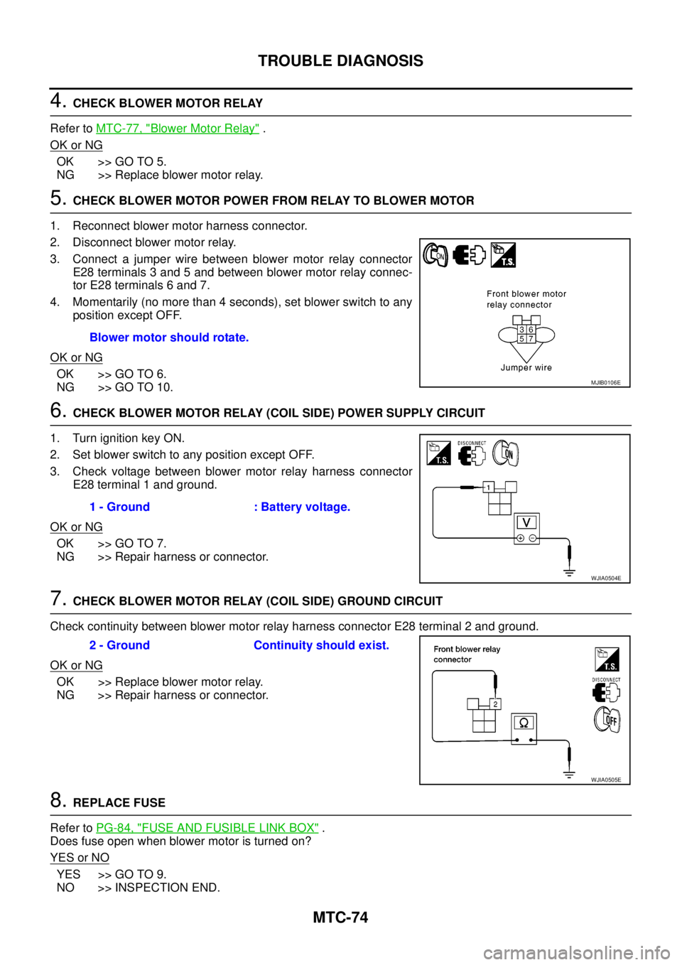
3. Connect a jumper wire between blower motor relay connector
E28 terminals 3 and 5 and between blower motor relay connec-
tor E28 terminals 6 and 7.
4. Momentarily (no more than 4 seconds), set blower switch to any
position except OFF.
OK or NG
OK >> GO TO 6.
NG >> GO TO 10.
6.CHECK BLOWER MOTOR RELAY (COIL SIDE) POWER SUPPLY CIRCUIT
1. Turn ignition key ON.
2. Set blower switch to any position except OFF.
3. Check voltage between blower motor relay harness connector
E28 terminal 1 and ground.
OK or NG
OK >> GO TO 7.
NG >> Repair harness or connector.
7.CHECK BLOWER MOTOR RELAY (COIL SIDE) GROUND CIRCUIT
Check continuity between blower motor relay harness connector E28 terminal 2 and ground.
OK or NG
OK >> Replace blower motor relay.
NG >> Repair harness or connector.
8.REPLACE FUSE
Refer toPG-84, "
FUSE AND FUSIBLE LINK BOX".
Does fuse open when blower motor is turned on?
YESorNO
YES >> GO TO 9.
NO >> INSPECTION END.Blower motor should rotate.
MJIB0106E
1 - Ground : Battery voltage.
WJIA0504E
2 - Ground Continuity should exist.
WJIA0505E
Page 2854 of 3171

CHARGING SYSTEM
SC-21
C
D
E
F
G
H
I
J
L
MA
B
SC
2.BATTERY VOLTAGE INSPECTION
1. Turn ignition switch OFF.
2. Disconnect alternator connector.
3. Turn ignition switch ON.
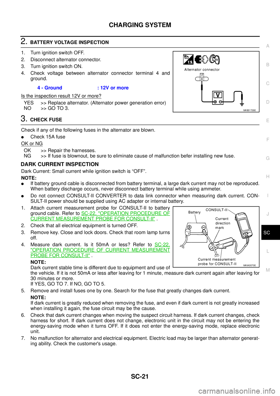
4. Check voltage between alternator connector terminal 4 and
ground.
Is the inspection result 12V or more?
YES >> Replace alternator. (Alternator power generation error)
NO >> GO TO 3.
3.CHECK FUSE
Check if any of the following fuses in the alternator are blown.
lCheck 15A fuse
OK or NG
OK >> Repair the harnesses.
NG >> If fuse is blownout, be sure to eliminate cause of malfunction befer installing new fuse.
DARK CURRENT INSPECTION
Dark Current: Small current while ignition switch is “OFF”.
NOTE:
lIf battery ground cable is disconnected from battery terminal, a large dark current may not be reproduced.
When battery discharge occurs, never disconnect battery terminal while using ammeter.
lDo not connect CONSULT-II CONVERTER to data link connector when measuring dark current. CON-
SULT-II power should be supplied using AC adapter or internal battery.
1. Attach current measurement probe for CONSULT-II to battery
ground cable. Refer toSC-22, "
OPERATION PROCEDURE OF
CURRENT MEASUREMENT PROBE FOR CONSULT-II".
2. Check that all electrical equipment is turned OFF.
3. Remove key. Close and lock doors. Check that room lamp turns
off.
4. Measure dark current. Is it 50mA or less? Refer toSC-22,
"OPERATION PROCEDURE OF CURRENT MEASUREMENT
PROBE FOR CONSULT-II".
NOTE:
Dark current stable time is different due to equipment and use of
the vehicle. If it is not 50mA or less after leaving for 1 minute, measure dark current again after leaving for
30 minutes or more.
If YES, GO TO 7. If NO, GO TO 5.
5. Remove and install fuses one by one. Search for the fuse that greatly changes dark current.
NOTE:
If dark current is greatly reduced when removing the fuse, and even if dark current is not greatly increased
when installing it again, the fuse circuit may be the cause.
6. Check that dark current changes when moving the suspect circuit harness. If dark current changes, check
harness for short. If dark current does not change, electronic unit in the circuit may not be entering the
energy-saving mode when it turns OFF. If it does not enter the energy-saving mode, replace electronic
unit.
7. No malfunction for alternator and electrical equipment. Electric load may be larger than alternator generat-
ing ability. Check the customer's usage.4 - Ground : 12V or more
MKIB1726E
MKIA0070E
Page 2936 of 3171
TROUBLE DIAGNOSIS
SRS-27
C
D
E
F
G
I
J
K
L
MA
B
SRS
6. Touch “SELF-DIAG [PAST]”.
7. If diagnostic codes are displayed on “SELF-DIAG [PAST]”, go to
step 10.
If no malfunction is detected on “SELF-DIAG [PAST]”, touch
“BACK” and go back to “SELECT DIAG MODE”.
8. Touch “TROUBLE DIAG RECORD”.
NOTE:
With “TROUBLE DIAG RECORD”, diagnosis results previ-
ously erased by a reset operation can be displayed.
9. Diagnostic code is displayed on “TROUBLE DIAG RECORD”.
10. Touch “PRINT”.
11. Compare diagnostic codes toSRS-28, "
CONSULT-II Diagnostic
Code Chart ("SELF-DIAG [PAST]" or "TROUBLE DIAG
RECORD")".
12. Touch “BACK” key of CONSULT-II until “SELECT SYSTEM”
appears.
13. Turn ignition switch OFF, and disconnect CONSULT-II, and both
battery cables.
BCIA0031E
WHIA0152E
SRS702
BCIA0031E
WHIA0153E