2005 NISSAN NAVARA key battery
[x] Cancel search: key batteryPage 667 of 3171
POWER DOOR LOCK — SUPER LOCK —
BL-83
C
D
E
F
G
H
J
K
L
MA
B
BL
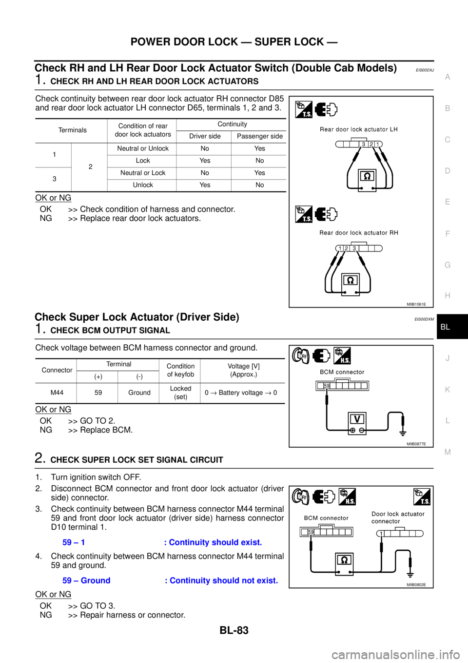
Check RH and LH Rear Door Lock Actuator Switch (Double Cab Models)EIS00DXJ
1.CHECK RH AND LH REAR DOOR LOCK ACTUATORS
Check continuity between rear door lock actuator RH connector D85
and rear door lock actuator LH connector D65, terminals 1, 2 and 3.
OK or NG
OK >> Check condition of harness and connector.
NG >> Replace rear door lock actuators.
Check Super Lock Actuator (Driver Side)EIS00DXM
1.CHECK BCM OUTPUT SIGNAL
Check voltage between BCM harness connector and ground.
OK or NG
OK >> GO TO 2.
NG >> Replace BCM.
2.CHECK SUPER LOCK SET SIGNAL CIRCUIT
1. Turn ignition switch OFF.
2. Disconnect BCM connector and front door lock actuator (driver
side) connector.
3. Check continuity between BCM harness connector M44 terminal
59 and front door lock actuator (driver side) harness connector
D10 terminal 1.
4. Check continuity between BCM harness connector M44 terminal
59 and ground.
OK or NG
OK >> GO TO 3.
NG >> Repair harness or connector.
Te r m i n a l sCondition of rear
door lock actuatorsContinuity
Driver side Passenger side
1
2Neutral or Unlock No Yes
Lock Yes No
3Neutral or Lock No Yes
Unlock Yes No
MIIB1061E
ConnectorTerminal
Condition
of keyfobVo l ta g e [V ]
(Approx.)
(+) (-)
M44 59 GroundLocked
(set)0®Battery voltage®0
MIIB0877E
59 – 1 : Continuity should exist.
59 – Ground : Continuity should not exist.
MIIB0802E
Page 685 of 3171

MULTI-REMOTE CONTROL SYSTEM
BL-101
C
D
E
F
G
H
J
K
L
MA
B
BL
Terminals and Reference Value for BCMEIS00DBI
*: Double cab modelsTerminalWire
ColorItem ConditionVoltage (V)
(Approx.)
3 Y Ignition switch ON or START Ignition switch ON or START Battery voltage
4 V Ignition switch ACC or ON Ignition switch ACC or ON Battery voltage
5RKeyswitchON (Key is inserted in key cylinder) Battery voltage
OFF (Key is removed from key cylinder) 0
12* L Rear door switch RHON (door open) 0
OFF (door closed) Battery voltage
14 LGFront door switch
(Passenger side)ON (door open) 0
OFF (door closed) Battery voltage
15 SBFront door switch
(Driver side)ON (door open) 0
OFF (door closed) Battery voltage
16* P Rear door switch LHON (door open) 0
OFF (door closed) Battery voltage
21 P CAN L — —
22 L CAN H — —
41 Y Power source (Fuse) — Battery voltage
55 B Ground — 0
57 W Power source (Fusible link) — Battery voltage
Page 689 of 3171
MULTI-REMOTE CONTROL SYSTEM
BL-105
C
D
E
F
G
H
J
K
L
MA
B
BL
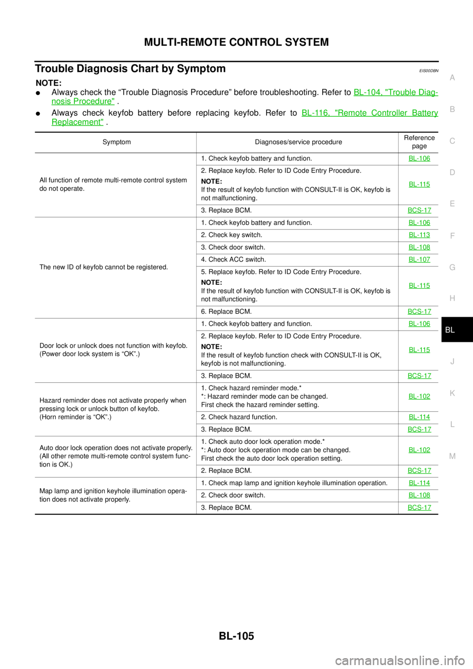
Trouble Diagnosis Chart by SymptomEIS00DBN
NOTE:
lAlways check the “Trouble Diagnosis Procedure” before troubleshooting. Refer toBL-104, "Trouble Diag-
nosis Procedure".
lAlways check keyfob battery before replacing keyfob. Refer toBL-116, "Remote Controller Battery
Replacement".
Symptom Diagnoses/service procedureReference
page
All function of remote multi-remote control system
do not operate.1. Check keyfob battery and function.BL-106
2. Replace keyfob. Refer to ID Code Entry Procedure.
NOTE:
If the result of keyfob function with CONSULT-II is OK, keyfob is
not malfunctioning.BL-115
3. Replace BCM.BCS-17
The new ID of keyfob cannot be registered.1. Check keyfob battery and function.BL-106
2. Check key switch.BL-113
3. Check door switch.BL-108
4. Check ACC switch.BL-107
5. Replace keyfob. Refer to ID Code Entry Procedure.
NOTE:
If the result of keyfob function with CONSULT-II is OK, keyfob is
not malfunctioning.BL-115
6. Replace BCM.BCS-17
Door lock or unlock does not function with keyfob.
(Power door lock system is “OK”.)1. Check keyfob battery and function.BL-106
2. Replace keyfob. Refer to ID Code Entry Procedure.
NOTE:
If the result of keyfob function check with CONSULT-II is OK,
keyfob is not malfunctioning.BL-115
3. Replace BCM.BCS-17
Hazard reminder does not activate properly when
pressing lock or unlock button of keyfob.
(Horn reminder is “OK”.)1. Check hazard reminder mode.*
*: Hazard reminder mode can be changed.
First check the hazard reminder setting.BL-102
2. Check hazard function.BL-114
3. Replace BCM.BCS-17
Auto door lock operation does not activate properly.
(All other remote multi-remote control system func-
tion is OK.)1. Check auto door lock operation mode.*
*: Auto door lock operation mode can be changed.
First check the auto door lock operation setting.BL-102
2. Replace BCM.BCS-17
Map lamp and ignition keyhole illumination opera-
tion does not activate properly.1. Check map lamp and ignition keyhole illumination operation.BL-1142. Check door switch.BL-108
3. Replace BCM.BCS-17
Page 690 of 3171

BL-106
MULTI-REMOTE CONTROL SYSTEM
Check Keyfob Battery and Function
EIS00DBO
1.CHECK KEYFOB BATTERY
1. Remove keyfob battery. Refer toBL-116, "
Remote Controller Battery Replacement".
2. Measure voltage between battery positive and negative termi-
nals, (+) and (-).
NOTE:
Keyfob does not function if battery is not set correctly.
OK or NG
OK >> GO TO 2.
NG >> Replace battery.
2.CHECK KEYFOB FUNCTION
With CONSULT-II
Check keyfob function in “DATA MONITOR” mode with CONSULT-II. When pushing each button of keyfob, the
corresponding monitor item should be turned as follows.
OK or NG
OK >> Keyfob is OK.
NG >> Replace keyfob.Voltage : 2.5 – 3.0V
SEL237W
Condition Monitor item
Pushing LOCK KEYLESS LOCK : ON
Pushing UNLOCK KEYLESS UNLOCK : ON
Press and hold UNLOCKRKE KEEP UNLK* : ON
*: Press and hold the unlock button for 3
seconds.
Pushing LOCK and UNLOCK at the
same timeRKE LCK-UNLOCK : ON
PIIA6468E
Page 697 of 3171
MULTI-REMOTE CONTROL SYSTEM
BL-113
C
D
E
F
G
H
J
K
L
MA
B
BL
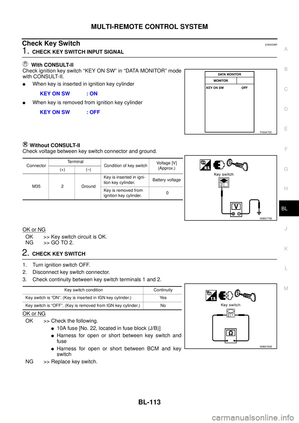
Check Key SwitchEIS00DBR
1.CHECK KEY SWITCH INPUT SIGNAL
With CONSULT-II
Check ignition key switch “KEY ON SW” in “DATA MONITOR” mode
with CONSULT-II.
lWhen key is inserted in ignition key cylinder
lWhen key is removed from ignition key cylinder
Without CONSULT-II
Check voltage between key switch connector and ground.
OK or NG
OK >> Key switch circuit is OK.
NG >> GO TO 2.
2.CHECK KEY SWITCH
1. Turn ignition switch OFF.
2. Disconnect key switch connector.
3. Check continuity between key switch terminals 1 and 2.
OK or NG
OK >> Check the following.
l10Afuse[No.22,locatedinfuseblock(J/B)]
lHarness for open or short between key switch and
fuse
lHarness for open or short between BCM and key
switch
NG >> Replace key switch.KEY ON SW : ON
KEY ON SW : OFF
PIIA6470E
ConnectorTerminal
Condition of key switchVo l ta g e [V ]
(Approx.)
(+) (–)
M35 2 GroundKey is inserted in igni-
tion key cylinder.Battery voltage
Key is removed from
ignition key cylinder.0
MIIB0779E
Key switch condition Continuity
Key switch is “ON”. (Key is inserted in IGN key cylinder.) Yes
Key switch is “OFF”. (Key is removed from IGN key cylinder.) No
MIIB0780E
Page 700 of 3171
BL-116
MULTI-REMOTE CONTROL SYSTEM
7. Select “NATS V.5.0”.
If “NATS V5.0” is not indicated, go toGI-50, "
CONSULT-II Data
Link Connector (DLC) Circuit".
8. Perform each diagnostic test mode according to each service
procedure.
For further information, see the CONSULT-II Operation Manual
NATS.
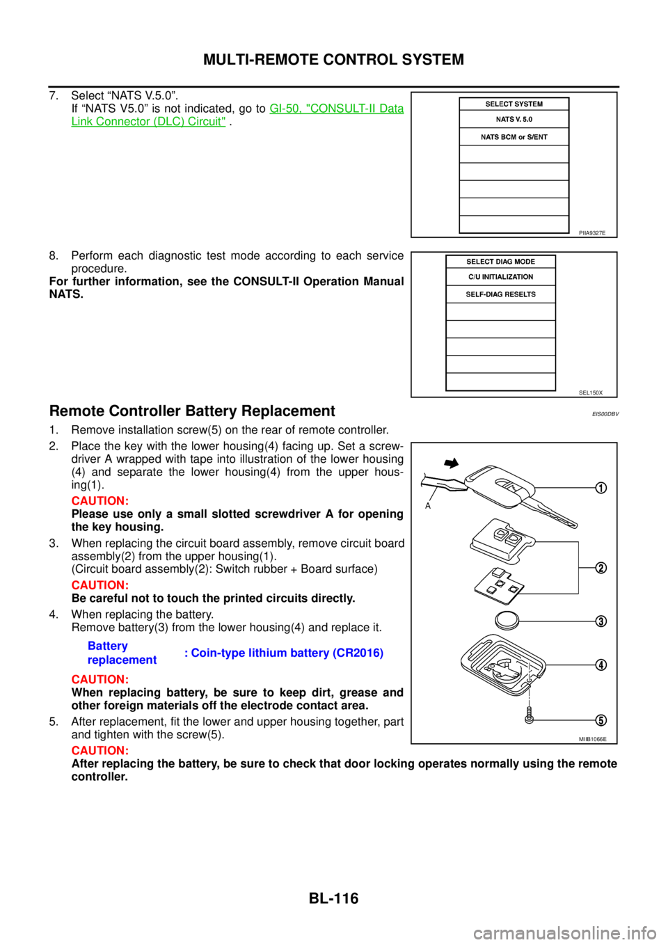
Remote Controller Battery ReplacementEIS00DBV
1. Remove installation screw(5) on the rear of remote controller.
2. Place the key with the lower housing(4) facing up. Set a screw-
driver A wrapped with tape into illustration of the lower housing
(4) and separate the lower housing(4) from the upper hous-
ing(1).
CAUTION:
Please use only a small slotted screwdriver A for opening
the key housing.
3. When replacing the circuit board assembly, remove circuit board
assembly(2) from the upper housing(1).
(Circuit board assembly(2): Switch rubber + Board surface)
CAUTION:
Be careful not to touch the printed circuits directly.
4. When replacing the battery.
Remove battery(3) from the lower housing(4) and replace it.
CAUTION:
When replacing battery, be sure to keep dirt, grease and
other foreign materials off the electrode contact area.
5. After replacement, fit the lower and upper housing together, part
and tighten with the screw(5).
CAUTION:
After replacing the battery, be sure to check that door locking operates normally using the remote
controller.
PIIA9327E
SEL150X
Battery
replacement: Coin-type lithium battery (CR2016)
MIIB1066E
Page 725 of 3171

THEFT WARNING SYSTEM
BL-141
C
D
E
F
G
H
J
K
L
MA
B
BL
2. A door is unlocked without using the keyfob.
3. Disconnect and connecting the battery connector before canceling armed phase.
POWER SUPPLY AND GROUND CIRCUIT
Power is supplied at all times
lthrough 10A fuse [No.19, located in the fuse block (J/B)]
lto combination meter (security indicator lamp) terminal 3
lthrough 50A fusible link (letterG, located in the fuse and fusible link box)
lto BCM terminal 57
lthrough 10A fuse [No. 21, located in the fuse block (J/B)]
lto BCM terminal 41
lthrough 15A fuse (No. 30, located in the fuse and fusible link box)
lto horn relay terminal 2
lthrough 20A fuse (No. 52, located in the IPDM E/R)
lthrough 20A fuse (No. 53, located in the IPDM E/R),
lto IPDM E/R internal CPU.
With the ignition switch in the ACC or ON position, power is supplied
lthrough 10A fuse [No. 4, located in the fuse block (J/B)]
lto BCM terminal 4.
Ground is supplied
lto BCM terminal 55
lthrough body grounds M21, M80 and M83
lto IPDM E/R terminals 38 and 59
lthrough body ground E21, E41 and E61.
INITIAL CONDITION TO ACTIVATE THE SYSTEM
The operation of the theft warning system is controlled by the engine hood and doors.
To activate the theft warning system, BCM must receive signals indicating the doors are closed and locked.
When a door is open, BCM terminal 12, 14, 15 or 16 receives a ground signal from each door switch.
When the engine hood is open, IPDM E/R terminal 41 receives a ground signal
THEFT WARNING SYSTEM ALARM OPERATION
The vehicle security system is triggered by
lopening a door
lopening the hood
ldetecting battery disconnect/connection.
The vehicle security system will be triggered once the system is in armed phase,
when BCM receives a ground signal at terminals 12, 14, 15, 16 (door switch) or IPDM E/R receives a ground
signal at terminal 41 (hood switch).
When the vehicle security system is triggered, siren control unit or horn is activate.
The alarm automatically turns off after 30 seconds, but will reactivate if the vehicle is tampered with again.
THEFT WARNING SYSTEM DEACTIVATION
To deactivate the theft warning system, a door must be unlocked with keyfob.
When the BCM receives either one of these signals or unlock signal from keyfob the theft warning system is
deactivated. (Disarmed phase)
CAN Communication System DescriptionEIS00DBY
Refer toLAN-23, "CAN COMMUNICATION".
Page 740 of 3171
BL-156
THEFT WARNING SYSTEM
TerminalsandReferenceValueforIPDME/R
EIS00DC3
*: When horn reminder is ON.
CONSULT-II Function (BCM)EIS00DC4
CONSULT-II can display each diagnostic item using the diagnostic test modes shown following.
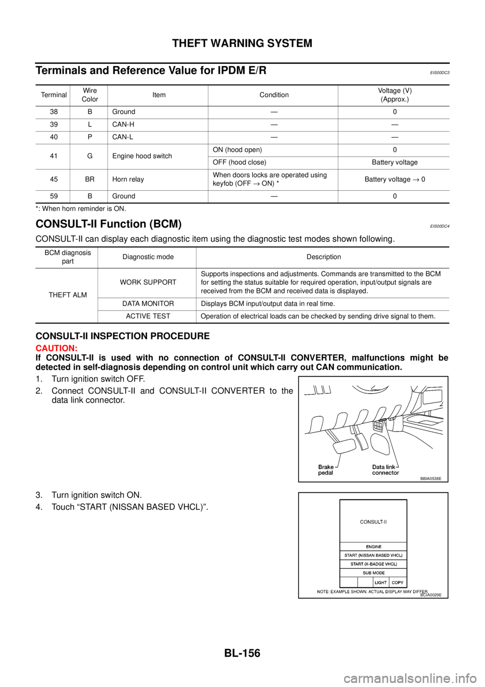
CONSULT-II INSPECTION PROCEDURE
CAUTION:
If CONSULT-II is used with no connection of CONSULT-II CONVERTER, malfunctions might be
detected in self-diagnosis depending on control unit which carry out CAN communication.
1. Turn ignition switch OFF.
2. Connect CONSULT-II and CONSULT-II CONVERTER to the
data link connector.
3. Turn ignition switch ON.
4. Touch “START (NISSAN BASED VHCL)”.
TerminalWire
ColorItem ConditionVoltage (V)
(Approx.)
38 B Ground — 0
39 L CAN-H — —
40 P CAN-L — —
41 G Engine hood switchON (hood open) 0
OFF (hood close) Battery voltage
45 BR Horn relayWhen doors locks are operated using
keyfob (OFF®ON) *Battery voltage®0
59 B Ground — 0
BCM diagnosis
partDiagnostic mode Description
THEFT ALMWORK SUPPORTSupports inspections and adjustments. Commands are transmitted to the BCM
for setting the status suitable for required operation, input/output signals are
received from the BCM and received data is displayed.
DATA MONITOR Displays BCM input/output data in real time.
ACTIVE TEST Operation of electrical loads can be checked by sending drive signal to them.
BBIA0538E
BCIA0029E