2005 NISSAN NAVARA flat tire
[x] Cancel search: flat tirePage 1341 of 3171

PRECAUTIONS
EI-3
C
D
E
F
G
H
J
K
L
MA
B
EI
PRECAUTIONSPFP:00001
Service NoticeEIS00DY1
lWhen removing or installing various parts, place a cloth or padding on the vehicle body to prevent
scratches.
lHandle trim, molding, instruments, grille, etc. carefully during removing or installing. Be careful not to soil
or damage them.
lApply sealing compound where necessary when installing parts.
lWhen applying sealing compound, be careful that the sealing compound does not protrude from parts.
lWhen replacing any metal parts (for example body outer panel, members, etc.), be sure to take rust pre-
vention measures.
Precautions for Supplemental Restraint System (SRS) “AIR BAG” and “SEAT
BELT PRE-TENSIONER”
EIS00DZ5
The Supplemental Restraint System such as “AIR BAG” and “SEAT BELT PRE-TENSIONER”, used along
with a front seat belt, helps to reduce the risk or severity of injury to the driver and front passenger for certain
types of collision. Information necessary to service the system safely is included in the SRS and SB section of
this Service Manual.
WARNING:
lTo avoid rendering the SRS inoperative, which could increase the risk of personal injury or death
in the event of a collision which would result in air bag inflation, all maintenance must be per-
formed by an authorized NISSAN/INFINITI dealer.
lImproper maintenance, including incorrect removal and installation of the SRS, can lead to per-
sonal injury caused by unintentional activation of the system. For removal of Spiral Cable and Air
Bag Module, see the SRS section.
lDo not use electrical test equipment on any circuit related to the SRS unless instructed to in this
Service Manual. SRS wiring harnesses can be identified by yellow and/or orange harnesses or
harness connectors.
Precautions for SRS “AIR BAG” and “SEAT BELT PRE-TENSIONER” ServiceEIS00DZ2
lDo not use electrical test equipment to check SRS circuits unless instructed to in this Service Manual.
lBefore servicing the SRS, turn ignition switch OFF, disconnect both battery cables and wait at least 3 min-
utes.
For approximately 3 minutes after the cables are removed, it is still possible for the air bag and seat belt
pre-tensioner to deploy. Therefore, do not work on any SRS connectors or wires until at least 3 minutes
have passed.
lThe air bag diagnosis sensor unit must always be installed with the arrow marks “Ü” pointing toward the
front of the vehicle for proper operation. Also check the air bag diagnosis sensor unit for cracks, deformi-
ties or rust before installation and replace as required.
lThe spiral cable must be aligned with the neutral position since its rotations are limited. Do not attempt to
turn steering wheel or column after removal of steering gear.
lHandle air bag module carefully. Always place driver and front passenger air bag modules with the pad
side facing upward and seat mounted front side air bag module standing with the stud bolt side facing
down.
lConduct self-diagnosis to check entire SRS for proper function after replacing any components.
lAfter air bag inflates, the front instrument panel assembly should be replaced if damaged.
Page 1607 of 3171
ON-VEHICLE SERVICE
FSU-7
C
D
F
G
H
I
J
K
L
MA
B
FSU
ON-VEHICLE SERVICEPFP:00000
Front Suspension PartsEES002KM
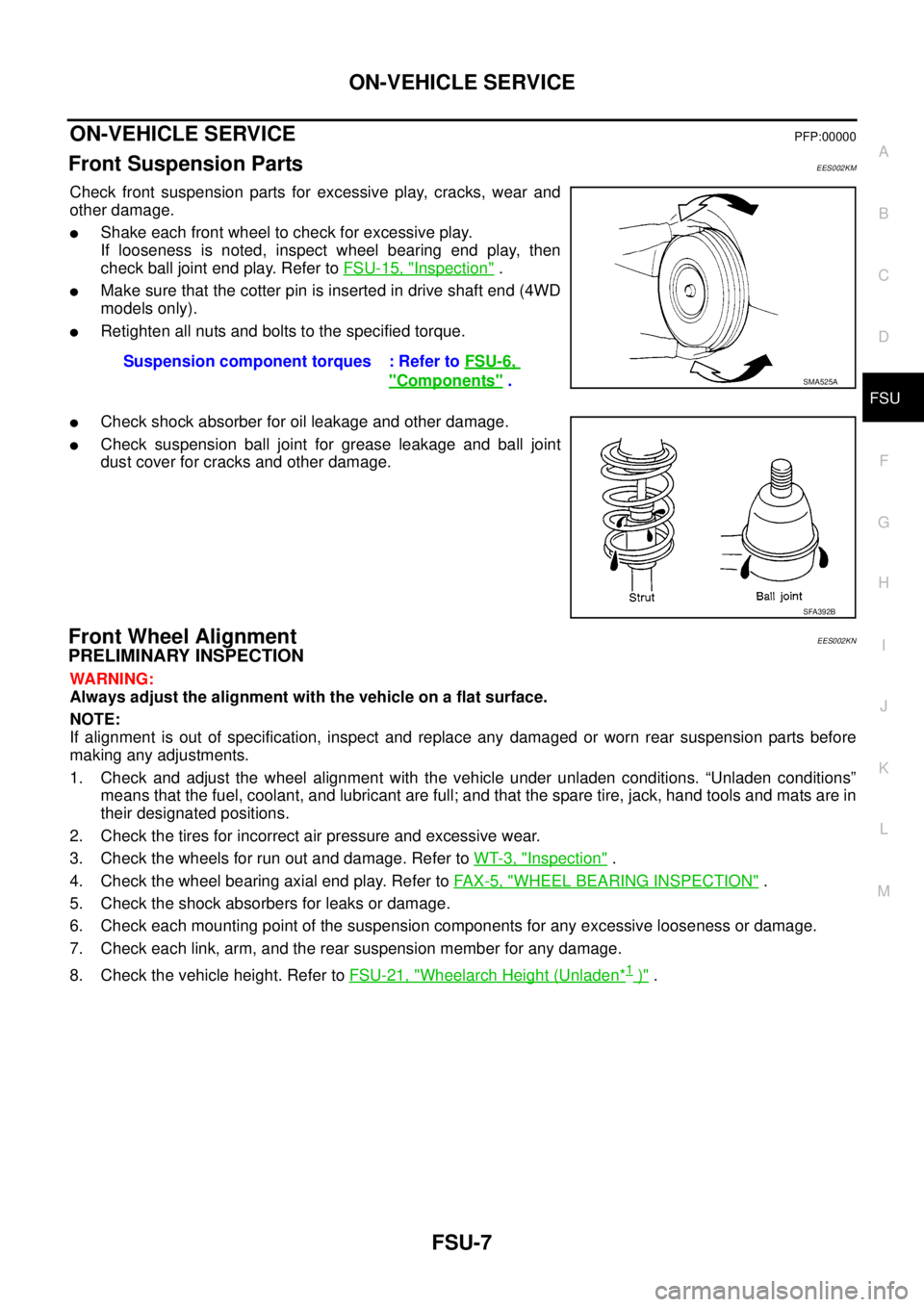
Check front suspension parts for excessive play, cracks, wear and
other damage.
lShake each front wheel to check for excessive play.
If looseness is noted, inspect wheel bearing end play, then
check ball joint end play. Refer toFSU-15, "
Inspection".
lMake sure that the cotter pin is inserted in drive shaft end (4WD
models only).
lRetighten all nuts and bolts to the specified torque.
lCheck shock absorber for oil leakage and other damage.
lCheck suspension ball joint for grease leakage and ball joint
dust cover for cracks and other damage.
Front Wheel AlignmentEES002KN
PRELIMINARY INSPECTION
WARNING:
Always adjust the alignment with the vehicle on a flat surface.
NOTE:
If alignment is out of specification, inspect and replace any damaged or worn rear suspension parts before
making any adjustments.
1. Check and adjust the wheel alignment with the vehicle under unladen conditions. “Unladen conditions”
means that the fuel, coolant, and lubricant are full; and that the spare tire, jack, hand tools and mats are in
their designated positions.
2. Check the tires for incorrect air pressure and excessive wear.
3. Check the wheels for run out and damage. Refer toWT-3, "
Inspection".
4. Check the wheel bearing axial end play. Refer toFA X - 5 , "
WHEEL BEARING INSPECTION".
5. Check the shock absorbers for leaks or damage.
6. Check each mounting point of the suspension components for any excessive looseness or damage.
7. Check each link, arm, and the rear suspension member for any damage.
8. Check the vehicle height. Refer toFSU-21, "
Wheelarch Height (Unladen*1)". Suspension component torques : Refer toFSU-6,
"Components".SMA525A
SFA392B
Page 1761 of 3171

IP-2
PRECAUTIONS
PRECAUTIONS
PFP:00001
Precautions for Supplemental Restraint System (SRS) “AIR BAG” and “SEAT
BELT PRE-TENSIONER”
EIS00DZ8
The Supplemental Restraint System such as “AIR BAG” and “SEAT BELT PRE-TENSIONER”, used along
with a front seat belt, helps to reduce the risk or severity of injury to the driver and front passenger for certain
types of collision. Information necessary to service the system safely is included in the SRS and SB section of
this Service Manual.
WARNING:
lTo avoid rendering the SRS inoperative, which could increase the risk of personal injury or death
in the event of a collision which would result in air bag inflation, all maintenance must be per-
formed by an authorized NISSAN/INFINITI dealer.
lImproper maintenance, including incorrect removal and installation of the SRS, can lead to per-
sonal injury caused by unintentional activation of the system. For removal of Spiral Cable and Air
Bag Module, see the SRS section.
lDo not use electrical test equipment on any circuit related to the SRS unless instructed to in this
Service Manual. SRS wiring harnesses can be identified by yellow and/or orange harnesses or
harness connectors.
Precautions for SRS “AIR BAG” and “SEAT BELT PRE-TENSIONER” ServiceEIS00DZ4
lDo not use electrical test equipment to check SRS circuits unless instructed to in this Service Manual.
lBefore servicing the SRS, turn ignition switch OFF, disconnect both battery cables and wait at least 3 min-
utes.
For approximately 3 minutes after the cables are removed, it is still possible for the air bag and seat belt
pre-tensioner to deploy. Therefore, do not work on any SRS connectors or wires until at least 3 minutes
have passed.
lThe air bag diagnosis sensor unit must always be installed with the arrow marks “Ü” pointing toward the
front of the vehicle for proper operation. Also check the air bag diagnosis sensor unit for cracks, deformi-
ties or rust before installation and replace as required.
lThe spiral cable must be aligned with the neutral position since its rotations are limited. Do not attempt to
turn steering wheel or column after removal of steering gear.
lHandle air bag module carefully. Always place driver and front passenger air bag modules with the pad
side facing upward and seat mounted front side air bag module standing with the stud bolt side facing
down.
lConduct self-diagnosis to check entire SRS for proper function after replacing any components.
lAfter air bag inflates, the front instrument panel assembly should be replaced if damaged.
Page 2111 of 3171
LT-28
HEADLAMP -CONVENTIONAL TYPE-
Aiming Adjustment
EKS00P7Y
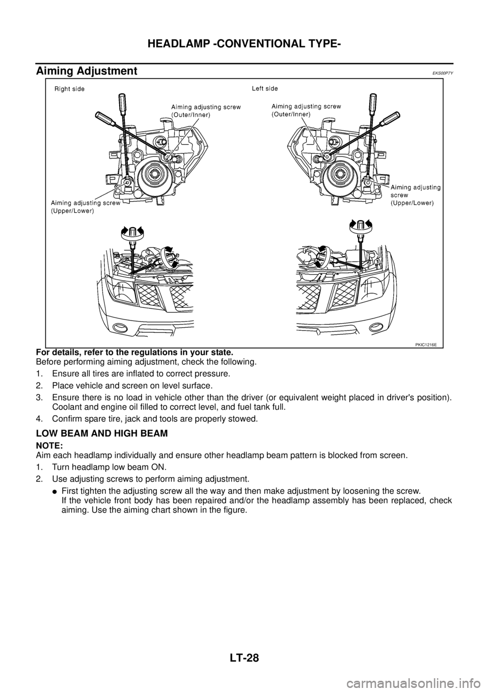
For details, refer to the regulations in your state.
Before performing aiming adjustment, check the following.
1. Ensure all tires are inflated to correct pressure.
2. Place vehicle and screen on level surface.
3. Ensure there is no load in vehicle other than the driver (or equivalent weight placed in driver's position).
Coolant and engine oil filled to correct level, and fuel tank full.
4. Confirm spare tire, jack and tools are properly stowed.
LOW BEAM AND HIGH BEAM
NOTE:
Aim each headlamp individually and ensure other headlamp beam pattern is blocked from screen.
1. Turn headlamp low beam ON.
2. Use adjusting screws to perform aiming adjustment.
lFirst tighten the adjusting screw all the way and then make adjustment by loosening the screw.
If the vehicle front body has been repaired and/or the headlamp assembly has been replaced, check
aiming. Use the aiming chart shown in the figure.
PKIC1216E
Page 2168 of 3171
FRONT FOG LAMP
LT-85
C
D
E
F
G
H
I
J
L
MA
B
LT
Aiming AdjustmentEKS00P4D
The fog lamp is a semi-sealed beam type which uses a replaceable halogen bulb. Before performing aiming
adjustment, make sure of the following.
lKeep all tires inflated to correct pressure.
lPlace vehicle on level surface.
lSee that vehicle is unloaded (except for full levels of coolant, engine oil and fuel, and spare tire, jack, and
tools). Have the driver or equivalent weight placed in driver's seat.
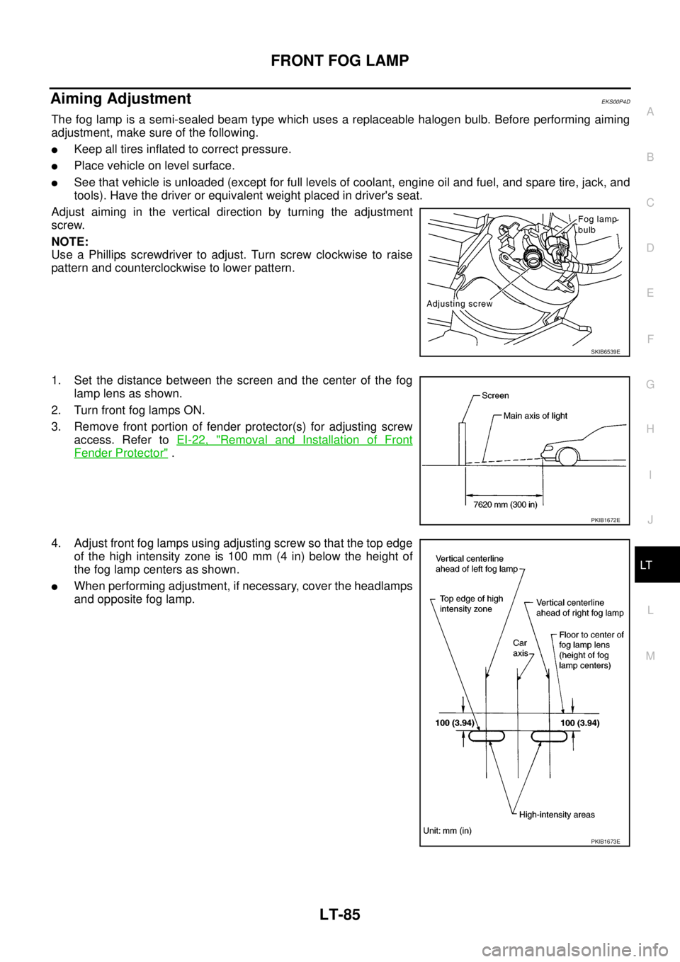
Adjust aiming in the vertical direction by turning the adjustment
screw.
NOTE:
Use a Phillips screwdriver to adjust. Turn screw clockwise to raise
pattern and counterclockwise to lower pattern.
1. Set the distance between the screen and the center of the fog
lamp lens as shown.
2. Turn front fog lamps ON.
3. Remove front portion of fender protector(s) for adjusting screw
access. Refer toEI-22, "
Removal and Installation of Front
Fender Protector".
4. Adjust front fog lamps using adjusting screw so that the top edge
of the high intensity zone is 100 mm (4 in) below the height of
the fog lamp centers as shown.
lWhen performing adjustment, if necessary, cover the headlamps
and opposite fog lamp.
SKIB6539E
PKIB1672E
PKIB1673E
Page 2309 of 3171
MA-34
CHASSIS AND BODY MAINTENANCE
Changing Rear Final Drive Oil (Rear Differential Gear Oil)
ELS001IW
CAUTION:
If using the vehicle for towing, the final drive oil must be replaced as specified. Refer toMA-8, "
PERI-
ODIC MAINTENANCE".
DRAINING
1. Stop the engine.
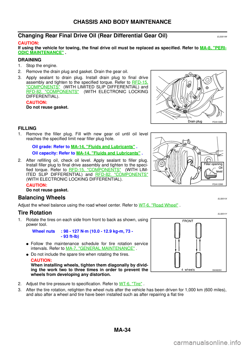
2. Remove the drain plug and gasket. Drain the gear oil.
3. Apply sealant to drain plug. Install drain plug to final drive
assembly and tighten to the specified torque. Refer toRFD-15,
"COMPONENTS"(WITH LIMITED SLIP DIFFERENTIAL) and
RFD-82, "
COMPONENTS"(WITH ELECTRONIC LOCKING
DIFFERENTIAL).
CAUTION:
Do not reuse gasket.
FILLING
1. Remove the filler plug. Fill with new gear oil until oil level
reaches the specified limit near filler plug hole.
2. After refilling oil, check oil level. Apply sealant to filler plug.
Install filler plug to final drive assembly and tighten to the speci-
fied torque. Refer toRFD-15, "
COMPONENTS"(WITH LIM-
ITED SLIP DIFFERENTIAL) andRFD-82, "
COMPONENTS"
(WITH ELECTRONIC LOCKING DIFFERENTIAL).
CAUTION:
Do not reuse gasket.
Balancing WheelsELS001IX
Adjust the wheel balance using the road wheel center. Refer toWT-6, "Road Wheel".
Tire RotationELS001IY
1. Rotate the tires on each side from front to back as shown, using
power tool.
lFollow the maintenance schedule for tire rotation service
intervals. Refer toMA-7, "
GENERAL MAINTENANCE".
lDo not include the spare tire when rotating the tires.
CAUTION:
When installing wheels, tighten them diagonally by divid-
ing the work two to three times in order to prevent the
wheels from developing any distortion.
2. Adjust the tire pressure to specification. Refer toWT-6, "
Tire".
3. After the tire rotation, retighten the wheel nuts after the vehicle has been driven for 1,000 km (600 miles),
and also after a wheel and tire have been installed such as after repairing a flat tire
PDIA1038E
Oil grade: Refer toMA-14, "Fluids and Lubricants".
Oil capacity: Refer toMA-14, "
Fluids and Lubricants".
PDIA1039E
Wheel nuts : 98 - 127 N·m (10.0 - 12.9 kg-m, 73 -
- 93 ft-lb)
SMA829C
Page 2819 of 3171
SB-2
PRECAUTIONS
PRECAUTIONS
PFP:00001
Precautions for Supplemental Restraint System (SRS) “AIR BAG” and “SEAT
BELT PRE-TENSIONER”
EHS0026D
The Supplemental Restraint System such as “AIR BAG” and “SEAT BELT PRE-TENSIONER”, used along
with a front seat belt, helps to reduce the risk or severity of injury to the driver and front passenger for certain
types of collision. Information necessary to service the system safely is included in the SRS and SB section of
this Service Manual.
WARNING:
lTo avoid rendering the SRS inoperative, which could increase the risk of personal injury or death
in the event of a collision which would result in air bag inflation, all maintenance must be per-
formed by an authorized NISSAN/INFINITI dealer.
lImproper maintenance, including incorrect removal and installation of the SRS, can lead to per-
sonal injury caused by unintentional activation of the system. For removal of Spiral Cable and Air
Bag Module, see the SRS section.
lDo not use electrical test equipment on any circuit related to the SRS unless instructed to in this
Service Manual. SRS wiring harnesses can be identified by yellow and/or orange harnesses or
harness connectors.
Precautions for Seat Belt ServiceEHS00265
CAUTION:
lBefore removing the seat belt pre-tensioner assembly, turn the ignition switch OFF, disconnect
both battery cables and wait at least 3 minutes.
lDo not use electrical test equipment for seat belt pre-tensioner connector.
lAfter replacing or reinstalling seat belt pre-tensioner assembly, or reconnecting seat belt pre-
tensioner assembly connector, ensure entire SRS operates properly. Refer toSRS-18, "
SRS Oper-
ation Check".
lDeploy seat belt pre-tensioner assembly before disposing. Refer toSRS-49, "DISPOSAL OF AIR
BAG MODULE AND SEAT BELT PRE-TENSIONER".
lDo not disassemble buckle or seat belt assembly.
lReplace anchor bolts if they are deformed or worn out.
lNever oil tongue and buckle.
lIf any component of seat belt assembly is questionable, do not repair. Replace the whole seat belt
assembly.
lIf webbing is cut, frayed, or damaged, replace seat belt assembly.
lWhen replacing seat belt assembly, use a genuine NISSAN seat belt assembly.
AFTER A COLLISION
WARNING:
lInspect all seat belt assemblies including retractors and attaching hardware after any collision.
lNISSAN recommends that all seat belt assemblies in use during a collision be replaced unless the
collision was minor and the belts show no damage and continue to operate properly. Failure to do
so could result in serious personal injury in an accident. Seat belt assemblies not in use during a
collision should also be replaced if either damage or improper operation is noted. Seat belt pre-
tensioner should be replaced even if the seat belts are not in use during a frontal collision in which
the air bags are deployed.
Replace any seat belt assembly (including anchor bolts) if:
lThe seat belt was in use at the time of a collision (except for minor collisions and the belts, retractors and
buckles show no damage and continue to operate properly).
lThe seat belt was damaged in an accident. (i.e., torn webbing, bent retractor or guide, etc.)
lThe seat belt attaching point was damaged in an accident. Inspect the seat belt attaching area for damage
or distortion and repair as necessary before installing a new seat belt assembly.
lAnchor bolts are deformed or worn out.
lThe seat belt pre-tensioner should be replaced even if the seat belts are not in use during the collision in
which the air bags are deployed.
Page 2912 of 3171
PRECAUTIONS
SRS-3
C
D
E
F
G
I
J
K
L
MA
B
SRS
PRECAUTIONSPFP:00001
Precautions for Supplemental Restraint System (SRS) “AIR BAG” and “SEAT
BELT PRE-TENSIONER”
EHS001Y8
The Supplemental Restraint System such as “AIR BAG” and “SEAT BELT PRE-TENSIONER”, used along
with a front seat belt, helps to reduce the risk or severity of injury to the driver and front passenger for certain
types of collision. Information necessary to service the system safely is included in the SRS and SB section of
this Service Manual.
WARNING:
lTo avoid rendering the SRS inoperative, which could increase the risk of personal injury or death
in the event of a collision which would result in air bag inflation, all maintenance must be per-
formed by an authorized NISSAN/INFINITI dealer.
lImproper maintenance, including incorrect removal and installation of the SRS, can lead to per-
sonal injury caused by unintentional activation of the system. For removal of Spiral Cable and Air
Bag Module, see the SRS section.
lDo not use electrical test equipment on any circuit related to the SRS unless instructed to in this
Service Manual. SRS wiring harnesses can be identified by yellow and/or orange harnesses or
harness connectors.
Precautions for SRS “AIR BAG” and “SEAT BELT PRE-TENSIONER” ServiceEHS001Y9
lDo not use electrical test equipment to check SRS circuits unless instructed to in this Service Manual.
lBefore servicing the SRS, turn ignition switch OFF, disconnect both battery cables and wait at least 3 min-
utes.
For approximately 3 minutes after the cables are removed, it is still possible for the air bag and seat belt
pre-tensioner to deploy. Therefore, do not work on any SRS connectors or wires until at least 3 minutes
have passed.
lDiagnosis sensor unit must always be installed with their arrow marks “Ü” pointing towards the front of the
vehicle for proper operation. Also check diagnosis sensor unit for cracks, deformities or rust before instal-
lation and replace as required.
lThe spiral cable must be aligned with the neutral position since its rotations are limited. Do not attempt to
turn steering wheel or column after removal of steering gear.
lHandle air bag module carefully. Always place driver and front passenger air bag modules with the pad
side facing upward and place front side air bag module standing with stud bolt side setting bottom.
lConduct self-diagnosis to check entire SRS for proper function after replacing any components.
lAfter air bag inflates, the front instrument panel assembly should be replaced if damaged.
lAlways replace instrument panel pad following front passenger air bag deployment.
Precautions for Trouble DiagnosisEHS001YA
When you read wiring diagrams, refer to the following:
lGI-15, "How to Read Wiring Diagrams"in GI section
lPG-4, "POWER SUPPLY ROUTING CIRCUIT"in PG section
When you perform trouble diagnosis, refer to the following:
lGI-11, "How to Follow Trouble Diagnoses"in GI section
lGI-24, "How to Perform Efficient Diagnosis for an Electrical Incident"in GI section
Check for any service bulletins before servicing the vehicle.