Page 1 of 3171

MODELD40 SERIES
2005 NISSAN EUROPE S.A.S.
All rights reserved. No part of this Electronic Service Manual may be reproduced or stored in a retrieval system, or transmitted in any
form, or by any means, electronic, mechanical, photocopying, recording or otherwise, without the prior written permission of Nissan
Europe S.A.S., Paris, France.
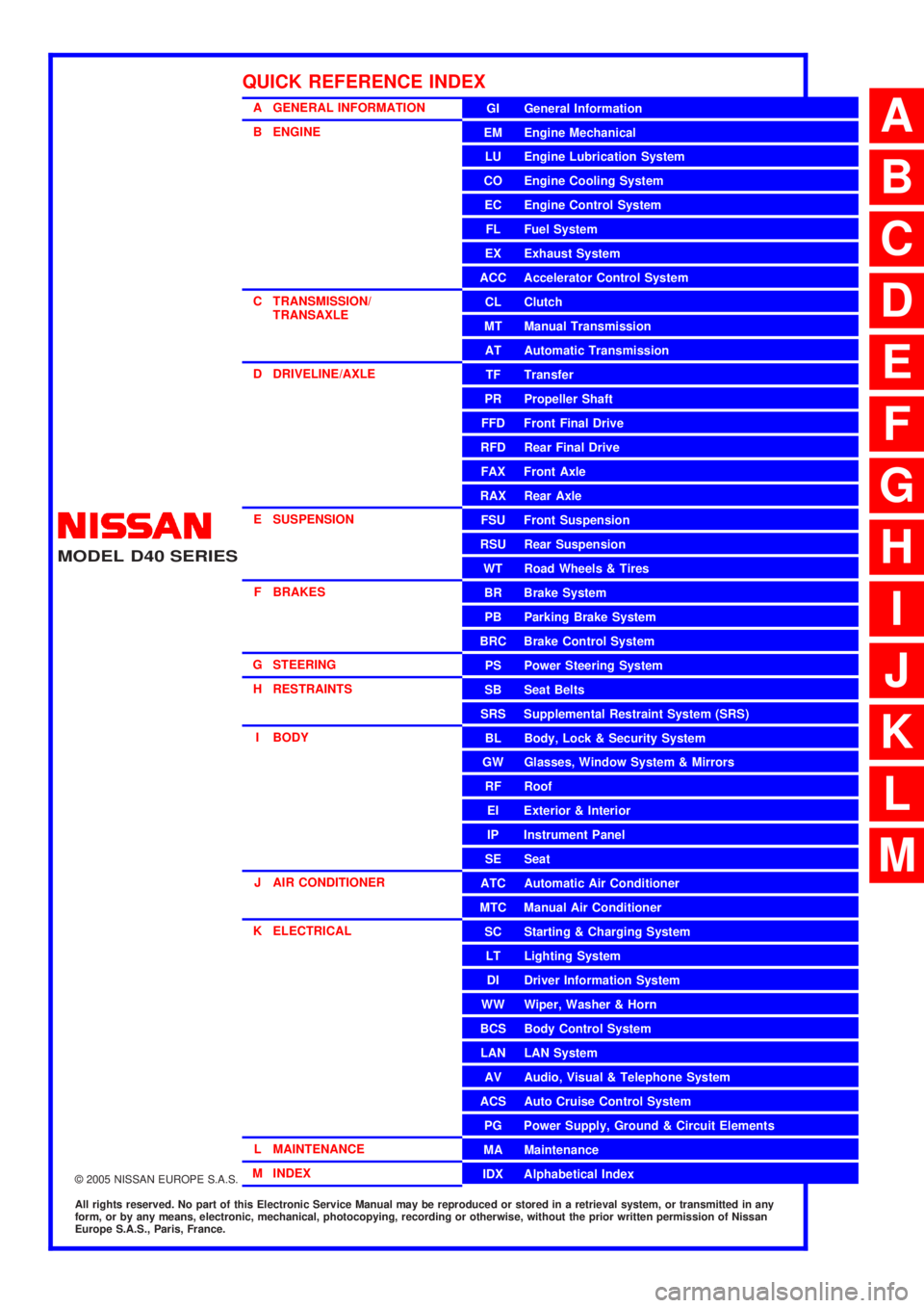
A GENERAL INFORMATION
B ENGINE
C TRANSMISSION/TRANSAXLE
D DRIVELINE/AXLE
E SUSPENSION F BRAKES
G STEERING H RESTRAINTS
I BODY
J AIR CONDITIONER
K ELECTRICAL
L MAINTENANCE
M INDEXGI General Information
EM Engine Mechanical
LU Engine Lubrication System
CO Engine Cooling System
EC Engine Control System
FL Fuel System
EX Exhaust System
ACC Accelerator Control System
CL Clutch
MTManualTransmission
AT Automatic Transmission
TF Transfer
PR Propeller Shaft
FFD Front Final Drive
RFD Rear Final Drive
FAX Front Axle
RAX Rear Axle
FSU Front Suspension
RSU Rear Suspension
WT Road Wheels & Tires
BR Brake System
PB Parking Brake System
BRC Brake Control System
PS Power Steering System
SB Seat Belts
SRS Supplemental Restraint System (SRS)
BL Body, Lock & Security System
GW Glasses, Window System & Mirrors
RF Roof
EI Exterior & Interior
IP Instrument Panel
SE Seat
ATC Automatic Air Conditioner
MTC Manual Air Conditioner
SC Starting & Charging System
LT Lighting System
DI Driver Information System
WW Wiper, Washer & Horn
BCS Body Control System
LAN LAN System
AV Audio, Visual & Telephone System
ACS Auto Cruise Control System
PG Power Supply, Ground & Circuit Elements
MA Maintenance
IDX Alphabetical Index
QUICK REFERENCE INDEX
A
B
C
D
E
F
G
H
I
J
K
L
M
Page 15 of 3171

PRECAUTIONS
AT-7
D
E
F
G
H
I
J
K
L
MA
B
AT
PRECAUTIONSPFP:00001
Precautions for Supplemental Restraint System (SRS) “AIR BAG” and “SEAT
BELT PRE-TENSIONER”
ECS00IPT
The Supplemental Restraint System such as “AIR BAG” and “SEAT BELT PRE-TENSIONER”, used along
with a front seat belt, helps to reduce the risk or severity of injury to the driver and front passenger for certain
types of collision. Information necessary to service the system safely is included in the SRS and SB section of
this Service Manual.
WARNING:
lTo avoid rendering the SRS inoperative, which could increase the risk of personal injury or death
in the event of a collision which would result in air bag inflation, all maintenance must be per-
formed by an authorized NISSAN/INFINITI dealer.
lImproper maintenance, including incorrect removal and installation of the SRS, can lead to per-
sonal injury caused by unintentional activation of the system. For removal of Spiral Cable and Air
Bag Module, see the SRS section.
lDo not use electrical test equipment on any circuit related to the SRS unless instructed to in this
Service Manual. SRS wiring harnesses can be identified by yellow and/or orange harnesses or
harness connectors.
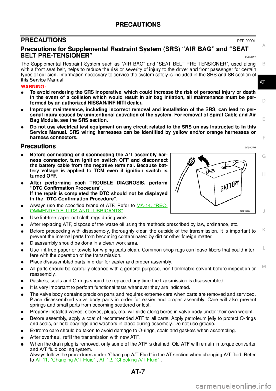
PrecautionsECS00IPR
lBefore connecting or disconnecting the A/T assembly har-
ness connector, turn ignition switch OFF and disconnect
the battery cable from the negative terminal. Because bat-
tery voltage is applied to TCM even if ignition switch is
turned OFF.
lAfter performing each TROUBLE DIAGNOSIS, perform
“DTC Confirmation Procedure”.
If the repair is completed the DTC should not be displayed
in the “DTC Confirmation Procedure”.
lAlways use the specified brand of ATF. Refer toMA-14, "REC-
OMMENDED FLUIDS AND LUBRICANTS".
lUse lint-free paper not cloth rags during work.
lAfter replacing ATF, dispose of the waste oil using the methods prescribed by law, ordinance, etc.
lBefore proceeding with disassembly, thoroughly clean the outside of the transmission. It is important to
prevent the internal parts from becoming contaminated by dirt or other foreign matter.
lDisassembly should be done in a clean work area.
lUse lint-free paper or towels for wiping parts clean. Common shop rags can leave fibers that could inter-
fere with the operation of the transmission.
lPlace disassembled parts in order for easier and proper assembly.
lAll parts should be carefully cleaned with a general purpose, non-flammable solvent before inspection or
reassembly.
lGaskets, seals and O-rings should be replaced any time the transmission is disassembled.
lIt is very important to perform functional tests whenever they are indicated.
lThe valve body contains precision parts and requires extreme care when parts are removed and serviced.
Place disassembled valve body parts in order for easier and proper assembly. Care will also prevent
springs and small parts from becoming scattered or lost.
lProperly installed valves, sleeves, plugs, etc. will slide along bores in valve body under their own weight.
lBefore assembly, apply a coat of recommended ATF to all parts. Apply petroleum jelly to protect O-rings
and seals, or hold bearings and washers in place during assembly. Do not use grease.
lExtreme care should be taken to avoid damage to O-rings, seals and gaskets when assembling.
lAfter overhaul, refill the transmission with new ATF.
lWhen the drain plug is removed, only some of the ATF is drained. Old ATF will remain in torque converter
and A/T fluid cooling system.
Always follow the procedures under “Changing A/T Fluid” in the AT section when changing A/T fluid. Refer
toAT-11, "
Changing A/T Fluid",AT-12, "Checking A/T Fluid".
SEF289H
Page 229 of 3171
ON-VEHICLE SERVICE
AT-221
D
E
F
G
H
I
J
K
L
MA
B
AT
15. Remove bolts A, B and C from control valve with TCM.
16. Remove control valve with TCM from transmission case.
CAUTION:
When removing, be careful with the manual valve notch and
manual plate height. Remove it vertically.
17. Remove A/T fluid temperature sensor 2 with bracket from con-
trol valve with TCM.
18. Remove bracket from A/T fluid temperature sensor 2.
19. Remove O-ring from A/T assembly harness connector.
Bolt symbol Length [mm (in)] Number of bolts
A42(1.65) 5
B55(2.17) 6
C40(1.57) 1
SCIA5139E
SCIA5142E
SCIA5301E
SCIA5264E
SCIA5155E
Page 232 of 3171
AT-224
ON-VEHICLE SERVICE
7. Install control valve with TCM in transmission case.
CAUTION:
lMake sure that turbine revolution sensor securely installs
turbine revolution sensor hole.
lHang down revolution sensor harness toward outside so
as not to disturb installation of control valve with TCM.
lAdjust A/T assembly harness connector of control valve
with TCM to terminal hole of transmission case.
lAssemble it so that manual valve cutout is engaged with
manual plate projection.
8. Install bolts A, B and C in control valve with TCM.
9. Tighten bolt 1, 2 and 3 temporarily to prevent dislocation. After
that tighten them in order (1®2®3), and then tighten other
bolts. Tighten control valve with TCM mounting bolts to the
specified torque. Refer toAT- 2 1 8 , "
COMPONENTS".
SCIA5034E
SCIA5142E
Bolt symbol Length [mm (in)] Number of bolts
A 42 (1.65) 5
B 55 (2.17) 6
C 40 (1.57) 1
SCIA5139E
SCIA5140E
Page 264 of 3171
AT-256
OVERHAUL
7. Pawl shaft 8. Seal ring 9. Needle bearing
10. Revolution sensor 11. Parking gear 12. Output shaft
13. Bearing race 14. Needle bearing 15. Manual plate
16. Parking rod 17. Manual shaft oil seal 18. Manual shaft
19. O-ring 20. Band servo anchor end pin 21. Detent spring
22. Spacer 23. Seal ring 24. Snap ring
25. Return spring 26. O-ring 27. Servo assembly
28. Snap ring 29. Sub-harness 30. Control valve with TCM
31. Bracket 32. A/T fluid temperature sensor 2 33. Oil pan
34. Magnet 35. Drain plug 36. Drain plug gasket
37. Oil pan mounting bolt 38. Oil pan gasket 39. Terminal cord assembly
40. O-ring 41. Retaining pin 42. Transmission case
Refer to GI section to make sure icons (symbol marks) in the figure. Refer toGI-10, "
Components".
However, refer to the following symbols for others.
*:Apply Anaerobic Liquid Gasket (Loctite 518) or equivalent.
Page 266 of 3171
AT-258
OVERHAUL
7. Self-sealing bolt 8. Seal ring 9. Needle bearing
10. Gasket 11. Revolution sensor 12. Parking gear
13. Output shaft 14. Bearing race 15. Needle bearing
16. Manual plate 17. Parking rod 18. Manual shaft oil seal
19. Manual shaft 20. O-ring 21. Band servo anchor end pin
22. Detent spring 23. Spacer 24. Seal ring
25. Return spring 26. O-ring 27. Servo assembly
28. Snap ring 29. Snap ring 30. Sub-harness
31. Control valve with TCM 32. Bracket 33. A/T fluid temperature sensor 2
34. Oil pan 35. Magnet 36. Drain plug
37. Drain plug gasket 38. Oil pan mounting bolt 39. Oil pan gasket
40. Terminal cord assembly 41. O-ring 42. Retaining pin
43. Transmission case
Refer to GI section to make sure icons (symbol marks) in the figure. Refer toGI-10, "
Components".
Page 278 of 3171
AT-270
DISASSEMBLY
33. Disconnect revolution sensor connector.
CAUTION:
Be careful not to damage connector.
34. Straighten terminal clips to free revolution sensor harness.
35. Remove bolts A, B and C from control valve with TCM.
36. Remove control valve with TCM from transmission case.
CAUTION:
When removing, be careful with manual valve notch and
manual plate height. Remove it vertically.
37. Remove A/T fluid temperature sensor 2 with bracket from con-
trol valve with TCM.
SCIA5024E
SCIA7023E
Bolt symbol Length [mm (in)] Number of bolts
A 42 (1.65) 5
B 55 (2.17) 6
C 40 (1.57) 1
SCIA5025E
SCIA5260E
SCIA5301E
Page 285 of 3171
DISASSEMBLY
AT-277
D
E
F
G
H
I
J
K
L
MA
B
AT
58. Removereversebrakepistonfromtransmissioncasewithcom-
pressed air. Refer toAT- 2 5 9 , "
Oil Channel".
CAUTION:
Care should be taken not to abruptly blow air. It makes pis-
tons incline, as the result, it becomes hard to disassemble
the pistons.
59. Remove D-rings from reverse brake piston.
60. Knock out retaining pin using a pin punch [commercial service
tool: 4 mm (0.16 in) dia.].
61. Remove manual shaft retaining pin using pair of pliers.
SCIA5047E
SCIA6330E
SCIA2328E
SCIA5218E