2005 NISSAN NAVARA manual transmission
[x] Cancel search: manual transmissionPage 1489 of 3171
ENGINE ASSEMBLY
EM-107
C
D
E
F
G
H
I
J
K
L
MA
EM
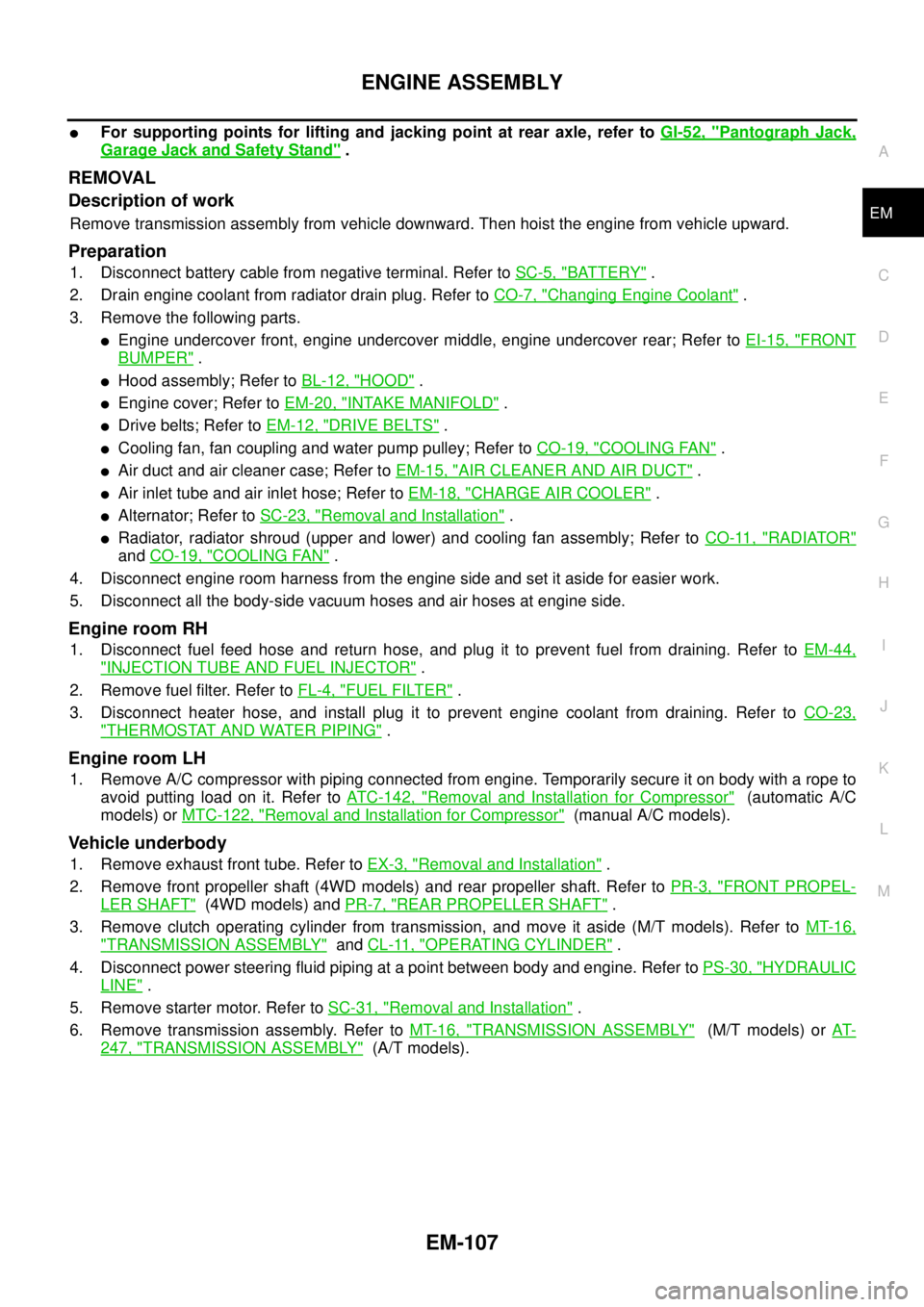
lFor supporting points for lifting and jacking point at rear axle, refer toGI-52, "Pantograph Jack,
Garage Jack and Safety Stand".
REMOVAL
Description of work
Remove transmission assembly from vehicle downward. Then hoist the engine from vehicle upward.
Preparation
1. Disconnect battery cable from negative terminal. Refer toSC-5, "BATTERY".
2. Drain engine coolant from radiator drain plug. Refer toCO-7, "
Changing Engine Coolant".
3. Remove the following parts.
lEngine undercover front, engine undercover middle, engine undercover rear; Refer toEI-15, "FRONT
BUMPER".
lHood assembly; Refer toBL-12, "HOOD".
lEngine cover; Refer toEM-20, "INTAKE MANIFOLD".
lDrive belts; Refer toEM-12, "DRIVE BELTS".
lCooling fan, fan coupling and water pump pulley; Refer toCO-19, "COOLING FAN".
lAir duct and air cleaner case; Refer toEM-15, "AIR CLEANER AND AIR DUCT".
lAir inlet tube and air inlet hose; Refer toEM-18, "CHARGE AIR COOLER".
lAlternator; Refer toSC-23, "Removal and Installation".
lRadiator, radiator shroud (upper and lower) and cooling fan assembly; Refer toCO-11, "RADIATOR"
andCO-19, "COOLING FAN".
4. Disconnect engine room harness from the engine side and set it aside for easier work.
5. Disconnect all the body-side vacuum hoses and air hoses at engine side.
Engine room RH
1. Disconnect fuel feed hose and return hose, and plug it to prevent fuel from draining. Refer toEM-44,
"INJECTION TUBE AND FUEL INJECTOR".
2. Remove fuel filter. Refer toFL-4, "
FUEL FILTER".
3. Disconnect heater hose, and install plug it to prevent engine coolant from draining. Refer toCO-23,
"THERMOSTAT AND WATER PIPING".
Engine room LH
1. Remove A/C compressor with piping connected from engine. Temporarily secure it on body with a rope to
avoid putting load on it. Refer toATC-142, "
Removal and Installation for Compressor"(automatic A/C
models) orMTC-122, "
Removal and Installation for Compressor"(manual A/C models).
Vehicle underbody
1. Remove exhaust front tube. Refer toEX-3, "Removal and Installation".
2. Remove front propeller shaft (4WD models) and rear propeller shaft. Refer toPR-3, "
FRONT PROPEL-
LER SHAFT"(4WD models) andPR-7, "REAR PROPELLER SHAFT".
3. Remove clutch operating cylinder from transmission, and move it aside (M/T models). Refer toMT-16,
"TRANSMISSION ASSEMBLY"andCL-11, "OPERATING CYLINDER".
4. Disconnect power steering fluid piping at a point between body and engine. Refer toPS-30, "
HYDRAULIC
LINE".
5. Remove starter motor. Refer toSC-31, "
Removal and Installation".
6. Remove transmission assembly. Refer toMT-16, "
TRANSMISSION ASSEMBLY"(M/T models) orAT-
247, "TRANSMISSION ASSEMBLY"(A/T models).
Page 1624 of 3171

GI-2
TIGHTENING TORQUE OF STANDARD BOLTS .... 55
Tightening Torque Table ......................................... 55
IDENTIFICATION INFORMATION ............................ 56
Model Variation ....................................................... 56
Identification Number .............................................. 57
VEHICLE IDENTIFICATION NUMBER
ARRANGEMENT ................................................. 57
IDENTIFICATION PLATE .................................... 58
ENGINE SERIAL NUMBER ................................ 58TRANSFER SERIAL NUMBER ........................... 58
AUTOMATIC TRANSMISSION NUMBER ........... 58
MANUAL TRANSMISSION NUMBER ................. 59
Dimensions ............................................................. 60
KING CAB ............................................................ 60
DOUBLE CAB ...................................................... 60
Wheels & Tyres ....................................................... 60
TERMINOLOGY ........................................................ 61
ISO 15031-2 Terminology List ................................. 61
Page 1627 of 3171
PRECAUTIONS
GI-5
C
D
E
F
G
H
I
J
K
L
MB
GI
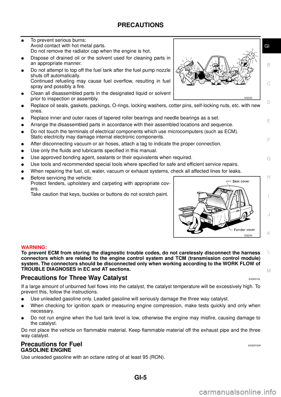
lTo prevent serious burns:
Avoid contact with hot metal parts.
Do not remove the radiator cap when the engine is hot.
lDispose of drained oil or the solvent used for cleaning parts in
an appropriate manner.
lDo not attempt to top off the fuel tank after the fuel pump nozzle
shuts off automatically.
Continued refueling may cause fuel overflow, resulting in fuel
spray and possibly a fire.
lClean all disassembled parts in the designated liquid or solvent
prior to inspection or assembly.
lReplace oil seals, gaskets, packings, O-rings, locking washers, cotter pins, self-locking nuts, etc. with new
ones.
lReplace inner and outer races of tapered roller bearings and needle bearings as a set.
lArrange the disassembled parts in accordance with their assembled locations and sequence.
lDo not touch the terminals of electrical components which use microcomputers (such as ECM).
Static electricity may damage internal electronic components.
lAfter disconnecting vacuum or air hoses, attach a tag to indicate the proper connection.
lUse only the fluids and lubricants specified in this manual.
lUse approved bonding agent, sealants or their equivalents when required.
lUse tools and recommended special tools where specified for safe and efficient service repairs.
lWhen repairing the fuel, oil, water, vacuum or exhaust systems, check all affected lines for leaks.
lBefore servicing the vehicle:
Protect fenders, upholstery and carpeting with appropriate cov-
ers.
Take caution that keys, buckles or buttons do not scratch paint.
WARNING:
To prevent ECM from storing the diagnostic trouble codes, do not carelessly disconnect the harness
connectors which are related to the engine control system and TCM (transmission control module)
system. The connectors should be disconnected only when working according to the WORK FLOW of
TROUBLE DIAGNOSES in EC and AT sections.
Precautions for Three Way CatalystEAS001GL
If a large amount of unburned fuel flows into the catalyst, the catalyst temperature will be excessively high. To
prevent this, follow the instructions.
lUse unleaded gasoline only. Leaded gasoline will seriously damage the three way catalyst.
lWhen checking for ignition spark or measuring engine compression, make tests quickly and only when
necessary.
lDo not run engine when the fuel tank level is low, otherwise the engine may misfire, causing damage to
the catalyst.
Do not place the vehicle on flammable material. Keep flammable material off the exhaust pipe and the three
way catalyst.
Precautions for FuelEAS001GM
GASOLINE ENGINE
Use unleaded gasoline with an octane rating of at least 95 (RON).
SGI233
SGI234
Page 1631 of 3171
HOW TO USE THIS MANUAL
GI-9
C
D
E
F
G
H
I
J
K
L
MB
GI
HOW TO USE THIS MANUALPFP:00008
DescriptionEAS001GS
This volume explains “Removal, Disassembly, Installation, Inspection and Adjustment” and “Trouble Diag-
noses”.
TermsEAS001GT
lThe captionsWARNINGandCAUTIONwarn you of steps that must be followed to prevent personal
injury and/or damage to some part of the vehicle.
WARNINGindicates the possibility of personal injury if instructions are not followed.
CAUTIONindicates the possibility of component damage if instructions are not followed.
BOLD TYPED STATEMENTSexceptWARNINGandCAUTIONgive you helpful information.
Standard value:Tolerance at inspection and adjustment.
Limit value:The maximum or minimum limit value that should not be exceeded at inspection and adjust-
ment.
UnitsEAS001GU
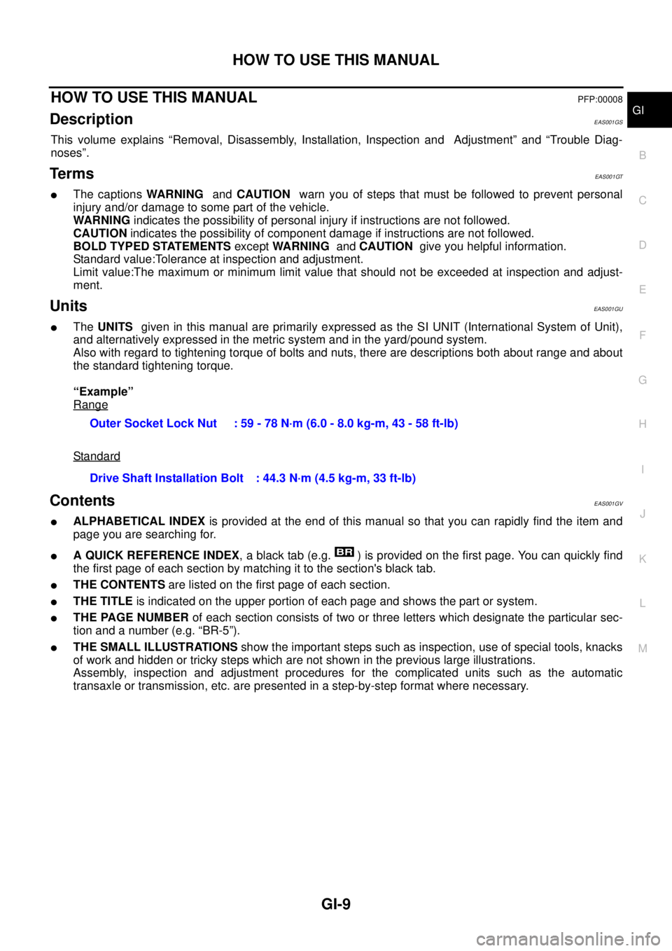
lTheUNITSgiven in this manual are primarily expressed as the SI UNIT (International System of Unit),
and alternatively expressed in the metric system and in the yard/pound system.
Also with regard to tightening torque of bolts and nuts, there are descriptions both about range and about
the standard tightening torque.
“Example”
Range
Standard
ContentsEAS001GV
lALPHABETICAL INDEXis provided at the end of this manual so that you can rapidly find the item and
page you are searching for.
lA QUICK REFERENCE INDEX, a black tab (e.g. ) is provided on the first page. You can quickly find
the first page of each section by matching it to the section's black tab.
lTHE CONTENTSare listed on the first page of each section.
lTHE TITLEis indicated on the upper portion of each page and shows the part or system.
lTHE PAGE NUMBERof each section consists of two or three letters which designate the particular sec-
tion and a number (e.g. “BR-5”).
lTHE SMALL ILLUSTRATIONSshow the important steps such as inspection, use of special tools, knacks
of work and hidden or tricky steps which are not shown in the previous large illustrations.
Assembly, inspection and adjustment procedures for the complicated units such as the automatic
transaxle or transmission, etc. are presented in a step-by-step format where necessary.Outer Socket Lock Nut : 59 - 78 N·m (6.0 - 8.0 kg-m, 43 - 58 ft-lb)
Drive Shaft Installation Bolt : 44.3 N·m (4.5 kg-m, 33 ft-lb)
Page 1645 of 3171

HOW TO USE THIS MANUAL
GI-23
C
D
E
F
G
H
I
J
K
L
MB
GI
AbbreviationsEAS001GZ
The followingABBREVIATIONSare used:
ABBREVIATION DESCRIPTION
A/C Air Conditioner
A/T Automatic Transaxle/Transmission
ATF Automatic Transmission Fluid
D
1Drive range 1st gear
D
2Drive range 2nd gear
D
3Drive range 3rd gear
D
4Drive range 4th gear
FR, RR Front, Rear
LH, RH Left-Hand, Right-Hand
M/T Manual Transaxle/Transmission
OD Overdrive
P/S Power Steering
SAE Society of Automotive Engineers, Inc.
SDS Service Data and Specifications
SST Special Service Tools
2WD 2-Wheel Drive
2
22nd range 2nd gear
2
12nd range 1st gear
1
21st range 2nd gear
1
11st range 1st gear
Page 1646 of 3171
GI-24
SERVICE INFORMATION FOR ELECTRICAL INCIDENT
SERVICE INFORMATION FOR ELECTRICAL INCIDENT
PFP:00000
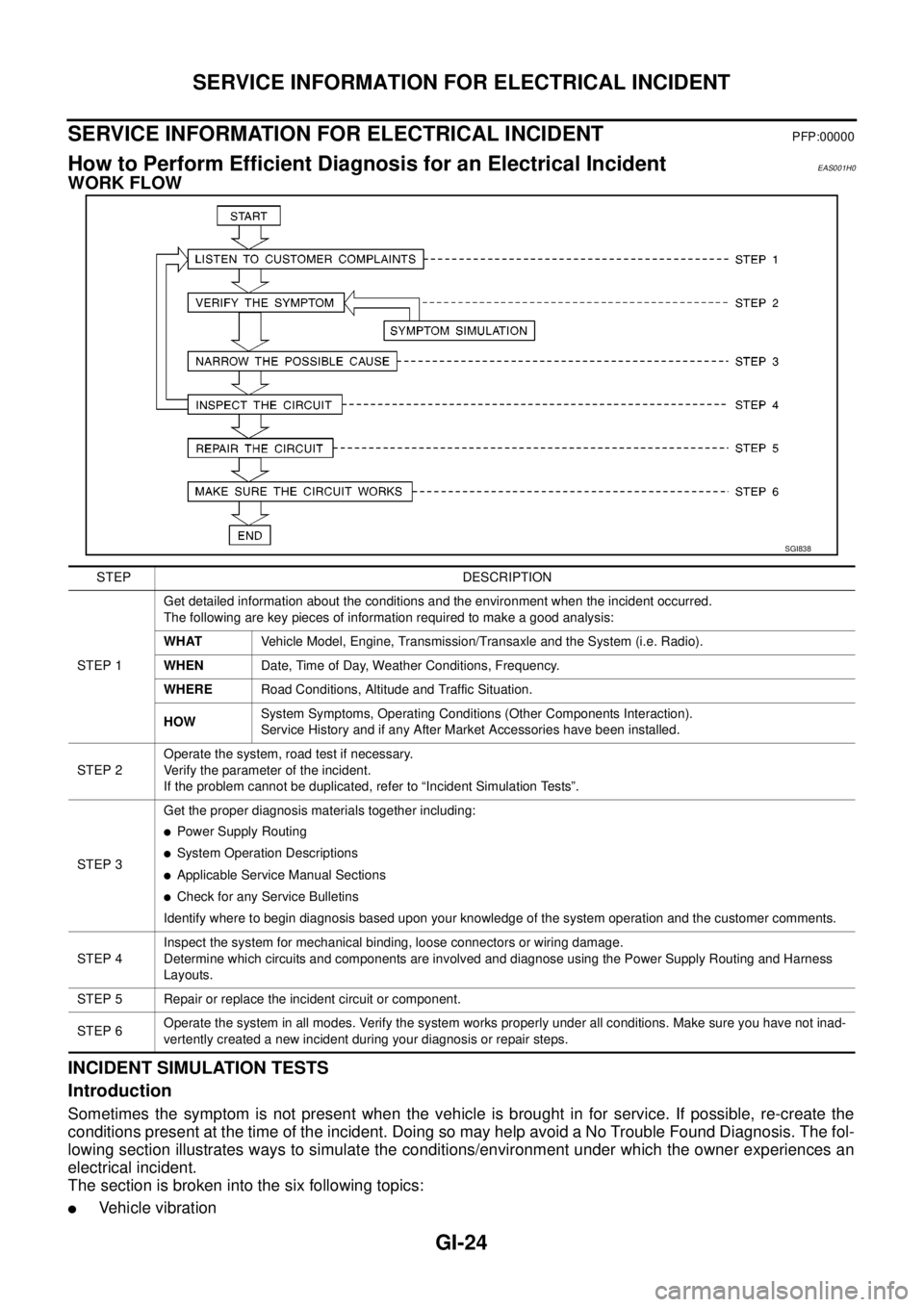
How to Perform Efficient Diagnosis for an Electrical IncidentEAS001H0
WORK FLOW
INCIDENT SIMULATION TESTS
Introduction
Sometimes the symptom is not present when the vehicle is brought in for service. If possible, re-create the
conditions present at the time of the incident. Doing so may help avoid a No Trouble Found Diagnosis. The fol-
lowing section illustrates ways to simulate the conditions/environment under which the owner experiences an
electrical incident.
The section is broken into the six following topics:
lVehicle vibration
SGI838
STEP DESCRIPTION
STEP 1Get detailed information about the conditions and the environment when the incident occurred.
The following are key pieces of information required to make a good analysis:
WHATVehicle Model, Engine, Transmission/Transaxle and the System (i.e. Radio).
WHENDate, Time of Day, Weather Conditions, Frequency.
WHERERoad Conditions, Altitude and Traffic Situation.
HOWSystem Symptoms, Operating Conditions (Other Components Interaction).
Service History and if any After Market Accessories have been installed.
STEP 2Operate the system, road test if necessary.
Verify the parameter of the incident.
If the problem cannot be duplicated, refer to “Incident Simulation Tests”.
STEP 3Get the proper diagnosis materials together including:
lPower Supply Routing
lSystem Operation Descriptions
lApplicable Service Manual Sections
lCheck for any Service Bulletins
Identify where to begin diagnosis based upon your knowledge of the system operation and the customer comments.
STEP 4Inspect the system for mechanical binding, loose connectors or wiring damage.
Determine which circuits and components are involved and diagnose using the Power Supply Routing and Harness
Layouts.
STEP 5 Repair or replace the incident circuit or component.
STEP 6Operate the system in all modes. Verify the system works properly under all conditions. Make sure you have not inad-
vertently created a new incident during your diagnosis or repair steps.
Page 1675 of 3171
TOW TRUCK TOWING
GI-53
C
D
E
F
G
H
I
J
K
L
MB
GI
TOW TRUCK TOWINGPFP:00000
To w Tr u c k To w i n gEAS001DI
WARNING:
lNever get under the vehicle while it is supported only by the jack. Always use safety stands to
support the frame when you have to get under the vehicle.
lPlace wheel chocks at both front and back of the wheels on the ground.
CAUTION:
lAll applicable local laws regarding the towing operation must be obeyed.
lIt is necessary to use proper towing equipment to avoid possible damage during towing opera-
tion. Towing is in accordance with Towing Procedure Manual at dealer.
lAlways attach safety chains before towing.
lWhen towing, make sure that the transmission, steering system and powertrain are in good order.
If any unit is damaged, dollies must be used.
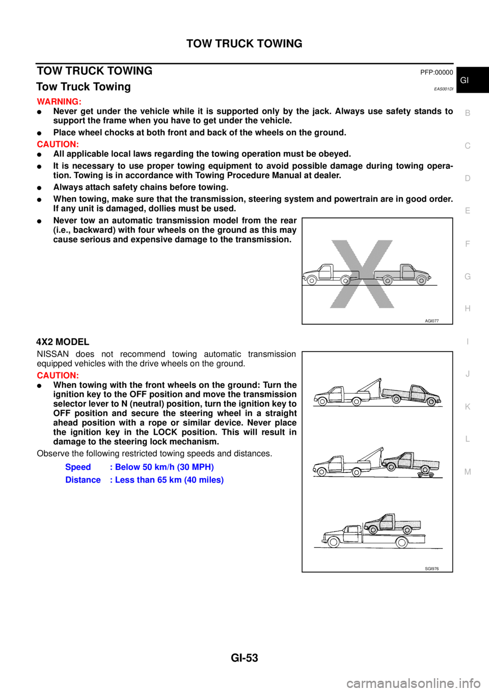
lNever tow an automatic transmission model from the rear
(i.e., backward) with four wheels on the ground as this may
cause serious and expensive damage to the transmission.
4X2 MODEL
NISSAN does not recommend towing automatic transmission
equipped vehicles with the drive wheels on the ground.
CAUTION:
lWhen towing with the front wheels on the ground: Turn the
ignition key to the OFF position and move the transmission
selector lever to N (neutral) position, turn the ignition key to
OFF position and secure the steering wheel in a straight
ahead position with a rope or similar device. Never place
the ignition key in the LOCK position. This will result in
damage to the steering lock mechanism.
Observe the following restricted towing speeds and distances.
AGI077
Speed : Below 50 km/h (30 MPH)
Distance : Less than 65 km (40 miles)
SGI976
Page 1681 of 3171
IDENTIFICATION INFORMATION
GI-59
C
D
E
F
G
H
I
J
K
L
MB
GI
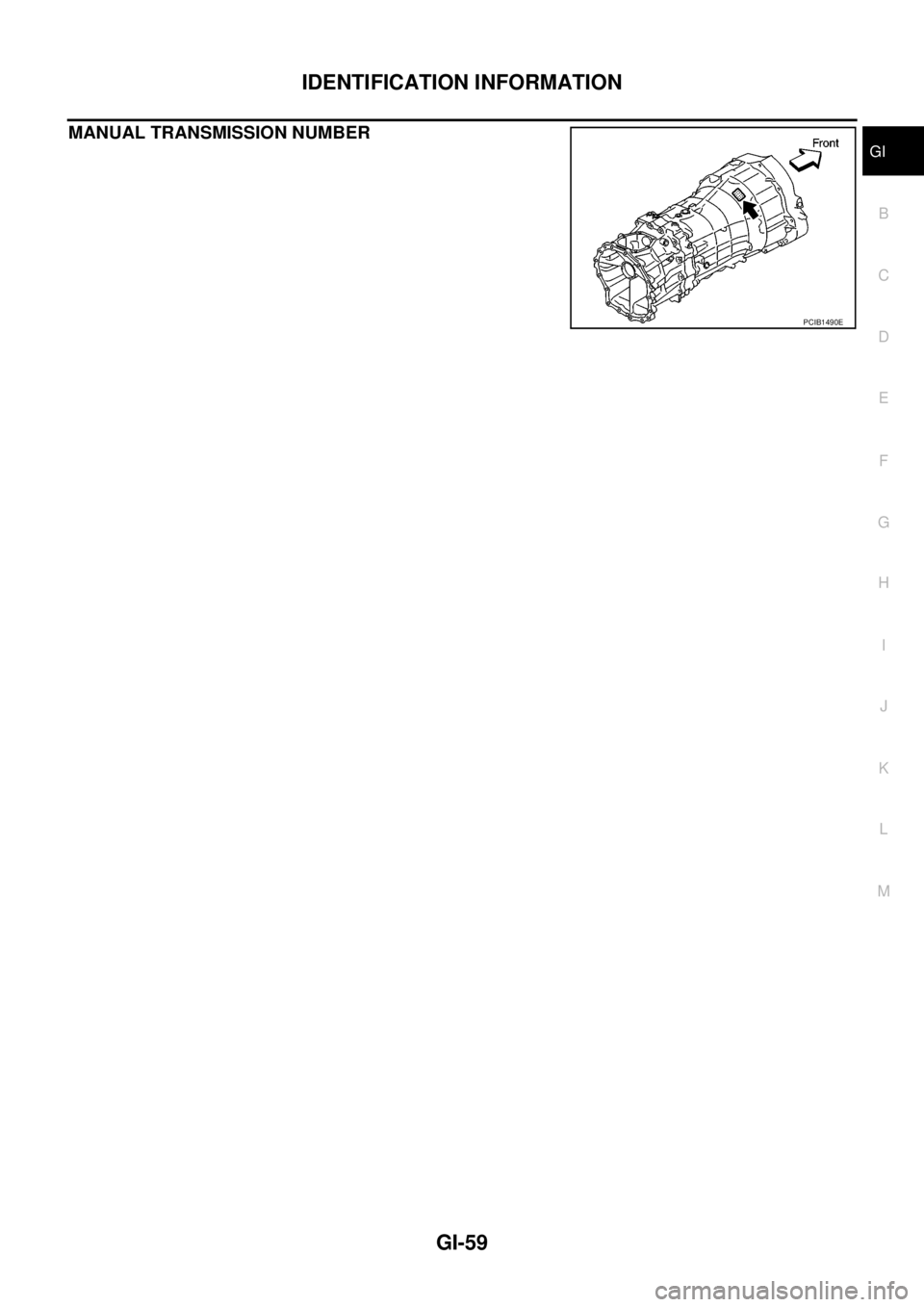
MANUAL TRANSMISSION NUMBER
PCIB1490E