2005 NISSAN NAVARA EI-15 FRONT BUMPER
[x] Cancel search: EI-15 FRONT BUMPERPage 252 of 3171
AT-244
A/T FLUID COOLER
A/T FLUID COOLER
PFP:21600
Removal and InstallationECS00G56
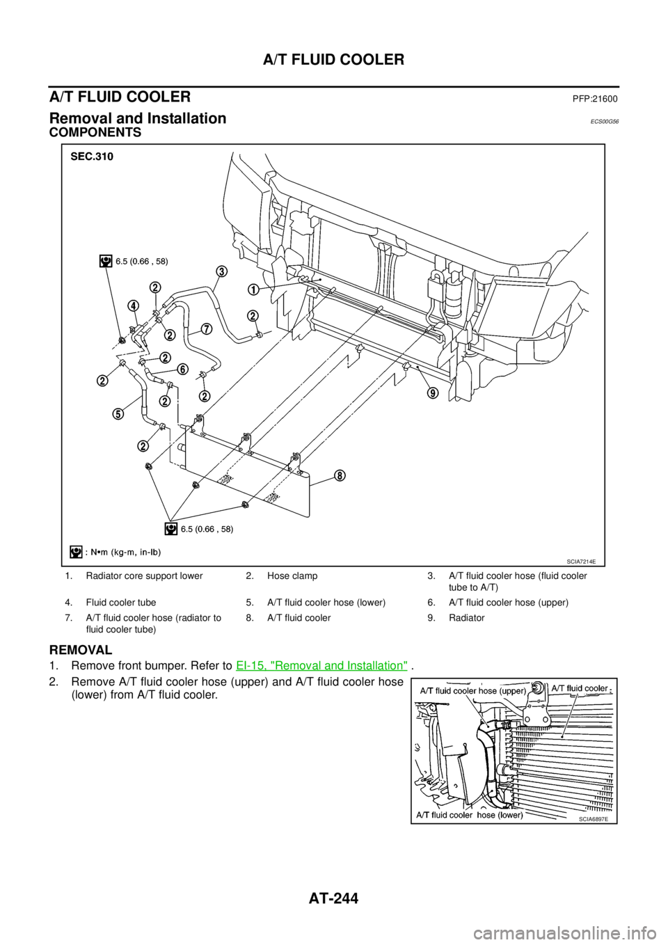
COMPONENTS
REMOVAL
1. Remove front bumper. Refer toEI-15, "Removal and Installation".
2. Remove A/T fluid cooler hose (upper) and A/T fluid cooler hose
(lower) from A/T fluid cooler.
1. Radiator core support lower 2. Hose clamp 3. A/T fluid cooler hose (fluid cooler
tube to A/T)
4. Fluid cooler tube 5. A/T fluid cooler hose (lower) 6. A/T fluid cooler hose (upper)
7. A/T fluid cooler hose (radiator to
fluid cooler tube)8. A/T fluid cooler 9. Radiator
SCIA7214E
SCIA6897E
Page 257 of 3171

TRANSMISSION ASSEMBLY
AT-249
D
E
F
G
H
I
J
K
L
MA
B
AT
5. Remove front valance center, engine undercover front, engine under cover middle and engine under
coverrear.RefertoEI-15, "
FRONT BUMPER".
6. Remove front cross member.
7. Remove main muffler. Refer toEX-2, "
EXHAUST SYSTEM".
8. Remove rear propeller shaft. Refer toPR-8, "
Removal and Installation".
9. Remove front propeller shaft. Refer toPR-4, "
Removal and Installation".
10. Remove starter motor. Refer toSC-31, "
Removal and Installation".
11. Remove control cable and bracket. Refer toAT- 2 1 0 , "
Control Cable Removal and Installation".
12. Disconnect fluid cooler tube.
13. Remove A/T fluid charging pipe from A/T assembly.
14. Remove O-ring from A/T fluid charging pipe.
15. Plug up openings such as A/T fluid charging pipe hole, etc.
16. Remove rear plate cover from rear plate.
17. Turn crankshaft to access and remove the four bolts for drive
plate and torque converter.
CAUTION:
When turning crankshaft, turn it clockwise as viewed from
the front of engine.
18. Support A/T assembly using a transmission jack.
CAUTION:
When setting transmission jack, be careful not to allow it to
collide against drain plug.
19. Remove protector (fuel tube), and then disconnect fuel tubes.
Refer toFL-7, "
FUEL COOLER". (4WD models)
20. Remove A/T cross member.
21. Remove engine mounting insulator (rear) from A/T assembly.
22. Disconnect the following:
lA/T assembly harness connector
lATP switch connector
l4LO switch connector
lWait detection switch connector
lTransfer control device connector
23. Support transfer assembly using a transmission jack. (4WD models)
24. Remove the wiring harness from bracket.
25. Remove bolts fixing A/T assembly to engine assembly.
26. Remove A/T assembly from the vehicle.
CAUTION:
lSecure torque converter to prevent it from dropping.
lSecure A/T assembly to a transmission jack.
27. Remove A/T air breather hose. Refer toAT- 2 4 3 , "
AIR
BREATHER HOSE".
28. Remove transfer assembly from A/T assembly. Refer toT F - 111 ,
"Removal and Installation". (4WD models)
SCIA6828E
SCIA6927E
SCIA2203E
Page 602 of 3171

BL-18
RADIATOR CORE SUPPORT
RADIATOR CORE SUPPORT
PFP:62500
Removal and InstallationEIS00DGJ
REMOVAL
1. Remove the hood assembly. Refer toBL-14, "Removal and Installation of Hood Assembly".
2. Remove the front grille. Refer toEI-19, "
FRONT GRILLE".
3. Remove the front bumper, bumper reinforcement and bumper bracket. Refer toEI-15, "
FRONT BUMPER"
.
4. Remove the headlamp assembly (LH/RH). Refer toLT-30, "
Removal and Installation".
5. Remove the air intake duct (Air guide). Refer toEM-15, "
AIR CLEANER AND AIR DUCT".
6. Remove the charge air cooler. (for YD25 engine models only) Refer toEM-18, "
CHARGE AIR COOLER".
7. Remove the power steering oil cooler. Refer toPS-30, "
HYDRAULIC LINE".
8. Remove the A/T fluid cooler and A/T fluid cooler tube mounting nuts. Refer toAT- 2 4 4 , "
A/T FLUID
COOLER".
9. Remove the hood lock assembly, and then remove the hood lock cable. Refer toBL-15, "
Removal and
Installation of Hood Lock Control".
10. Remove the horn harness connector.
11. Disconnect the ambient sensor connector and remove the ambient sensor. Refer toAT C - 11 7 , "
Removal
and Installation".
12. Remove the mounting harness clip on radiator core support assembly, the harness is separate.
13. Remove the upper radiator bracket. Refer toCO-11, "
RADIATOR".
1. Radiator core support assembly 2. Air intake duct (Air guide) RH 3. Air intake duct (Air guide) LH
4. Horn (Low) 5. Headlamp lower bracket RH 6. Headlamp lower bracket LH
7. Headlamp side bracket RH 8. Headlamp side bracket LH
MIIB0979E
Page 604 of 3171
BL-20
FRONT FENDER
FRONT FENDER
PFP:63100
Removal and InstallationEIS00BK0
REMOVAL
1. Remove the front bumper. Refer toEI-15, "FRONT BUMPER".
2. Remove the headlamp. Refer toLT-30, "
Removal and Installation".
3. Remove the front fender protector. Refer toEI-22, "
Removal and Installation of Front Fender Protector".
4. Remove the front side turn signal lamp. Refer toLT- 111 , "
Removal and Installation of Front Turn Signal
Lamp".
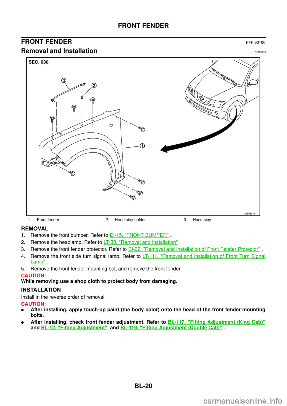
5. Remove the front fender mounting bolt and remove the front fender.
CAUTION:
While removing use a shop cloth to protect body from damaging.
INSTALLATION
Install in the reverse order of removal.
CAUTION:
lAfter installing, apply touch-up paint (the body color) onto the head of the front fender mounting
bolts.
lAfter installing, check front fender adjustment. Refer toBL-117, "Fitting Adjustment (King Cab)"
andBL-12, "Fitting Adjustment"andBL-119, "Fitting Adjustment (Double Cab)".
1. Front fender 2. Hood stay holder 3. Hood stay
MIIB0557E
Page 905 of 3171
WATER PUMP
CO-21
C
D
E
F
G
H
I
J
K
L
MA
CO
WAT E R P U MPPFP:21020
ComponentsEBS01F6K
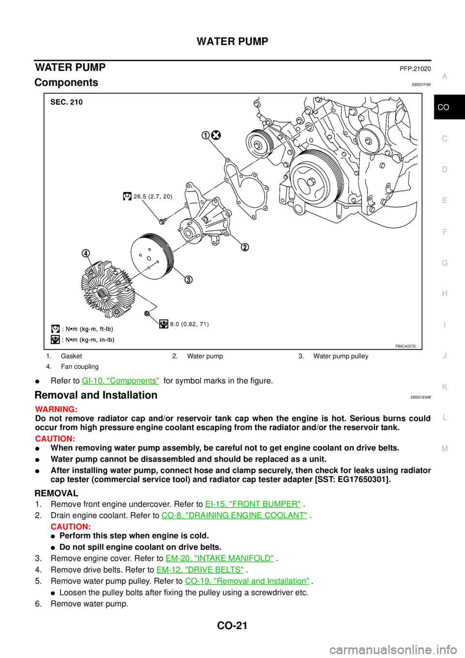
lRefer toGI-10, "Components"for symbol marks in the figure.
Removal and InstallationEBS01E6W
WARNING:
Do not remove radiator cap and/or reservoir tank cap when the engine is hot. Serious burns could
occur from high pressure engine coolant escaping from the radiator and/or the reservoir tank.
CAUTION:
lWhen removing water pump assembly, be careful not to get engine coolant on drive belts.
lWater pump cannot be disassembled and should be replaced as a unit.
lAfter installing water pump, connect hose and clamp securely, then check for leaks using radiator
cap tester (commercial service tool) and radiator cap tester adapter [SST: EG17650301].
REMOVAL
1. Remove front engine undercover. Refer toEI-15, "FRONT BUMPER".
2. Drain engine coolant. Refer toCO-8, "
DRAINING ENGINE COOLANT".
CAUTION:
lPerform this step when engine is cold.
lDo not spill engine coolant on drive belts.
3. Remove engine cover. Refer toEM-20, "
INTAKE MANIFOLD".
4. Remove drive belts. Refer toEM-12, "
DRIVE BELTS".
5. Remove water pump pulley. Refer toCO-19, "
Removal and Installation".
lLoosen the pulley bolts after fixing the pulley using a screwdriver etc.
6. Remove water pump.
1. Gasket 2. Water pump 3. Water pump pulley
4. Fan coupling
PBIC4057E
Page 908 of 3171
CO-24
THERMOSTAT AND WATER PIPING
Removal and Installation
EBS01E6X
WARNING:
Do not remove radiator cap and/or reservoir tank cap when engine is hot. Serious burns could occur
from high pressure engine coolant escaping from radiator and/or reservoir tank.
REMOVAL
1. Remove front engine undercover and middle engine undercover. Refer toEI-15, "FRONT BUMPER".
2. Drain engine coolant from radiator drain plug at the bottom of radiator, and from water drain plug at the
side of cylinder block. Refer toCO-7, "
Changing Engine Coolant"andEM-110, "CYLINDER BLOCK".
CAUTION:
Perform this step when engine is cold.
3. Remove engine cover. Refer toEM-20, "
INTAKE MANIFOLD".
4. Disconnect radiator hoses (upper and lower) from engine side. Refer toCO-11, "
RADIATOR".
5. Remove air inlet pipe and air duct between air cleaner case and turbocharger. Refer toEM-15, "
AIR
CLEANER AND AIR DUCT"andEM-28, "TURBO CHARGER".
6. Remove water outlet, water inlet and thermostat.
7. Remove thermostat housing.
8. Disconnect heater return hose and water hoses at heater return pipe side, and remove heater return pipe.
9. Remove oil level gauge guide mounting bolt, vacuum hoses (to turbocharger boost control solenoid valve)
and spill hose. Refer toEM-36, "
OIL PAN AND OIL STRAINER",EM-20, "INTAKE MANIFOLD"andEM-
44, "INJECTION TUBE AND FUEL INJECTOR".
10. Disconnect water hoses (to EGR cooler) (A/T models), vacuum hoses and heater feed hose at heater
feed pipe side, and remove heater feed pipe. Refer toEM-20, "
INTAKE MANIFOLD".
INSPECTION AFTER REMOVAL
Thermostat
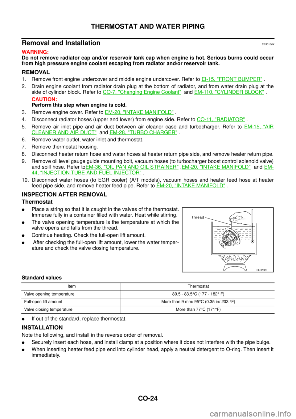
lPlace a string so that it is caught in the valves of the thermostat.
Immerse fully in a container filled with water. Heat while stirring.
lThe valve opening temperature is the temperature at which the
valve opens and falls from the thread.
lContinue heating. Check the full-open lift amount.
lAfter checking the full-open lift amount, lower the water temper-
ature and check the valve closing temperature.
Standard values
lIf out of the standard, replace thermostat.
INSTALLATION
Note the following, and install in the reverse order of removal.
lSecurely insert each hose, and install clamp at a position where it does not interfere with the pipe bulge.
lWhen inserting heater feed pipe end into cylinder head, apply a neutral detergent to O-ring. Then insert it
immediately.
SLC252B
Item Thermostat
Valve opening temperature 80.5 - 83.5°C (177 - 182°F)
Full-open lift amount More than 9 mm/ 95°C (0.35 in/ 203°F)
Valve closing temperature More than 77°C(171°F)
Page 1353 of 3171
FRONT BUMPER
EI-15
C
D
E
F
G
H
J
K
L
MA
B
EI
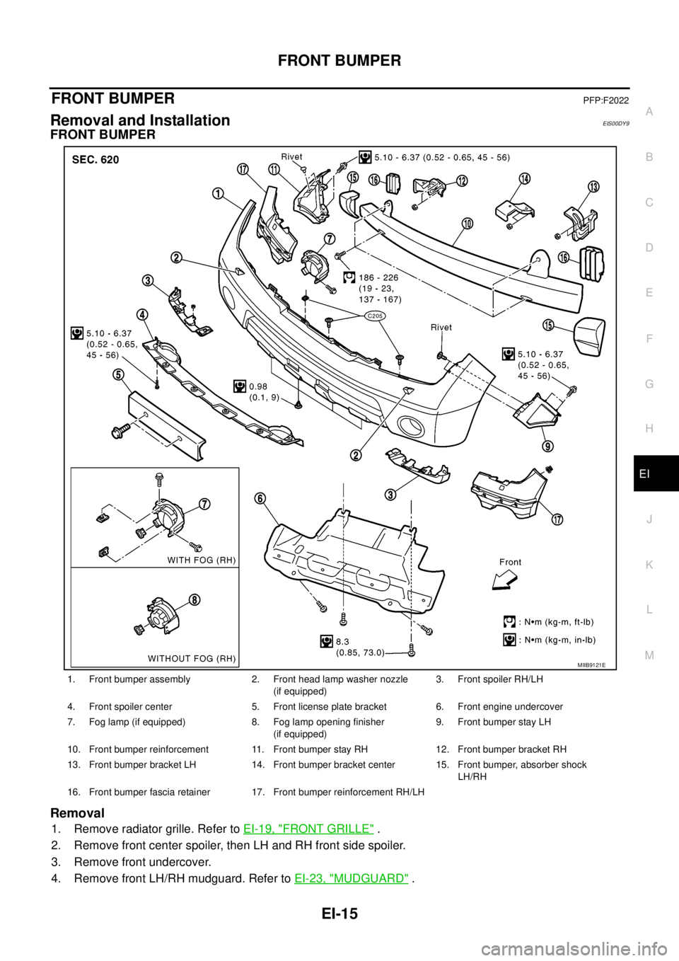
FRONT BUMPERPFP:F2022
Removal and InstallationEIS00DY9
FRONT BUMPER
Removal
1. Remove radiator grille. Refer toEI-19, "FRONT GRILLE".
2. Remove front center spoiler, then LH and RH front side spoiler.
3. Remove front undercover.
4. Remove front LH/RH mudguard. Refer toEI-23, "
MUDGUARD".
1. Front bumper assembly 2. Front head lamp washer nozzle
(if equipped)3. Front spoiler RH/LH
4. Front spoiler center 5. Front license plate bracket 6. Front engine undercover
7. Fog lamp (if equipped) 8. Fog lamp opening finisher
(if equipped)9. Front bumper stay LH
10. Front bumper reinforcement 11. Front bumper stay RH 12. Front bumper bracket RH
13. Front bumper bracket LH 14. Front bumper bracket center 15. Front bumper, absorber shock
LH/RH
16. Front bumper fascia retainer 17. Front bumper reinforcement RH/LH
MIIB9121E
Page 1395 of 3171
DRIVE BELTS
EM-13
C
D
E
F
G
H
I
J
K
L
MA
EM
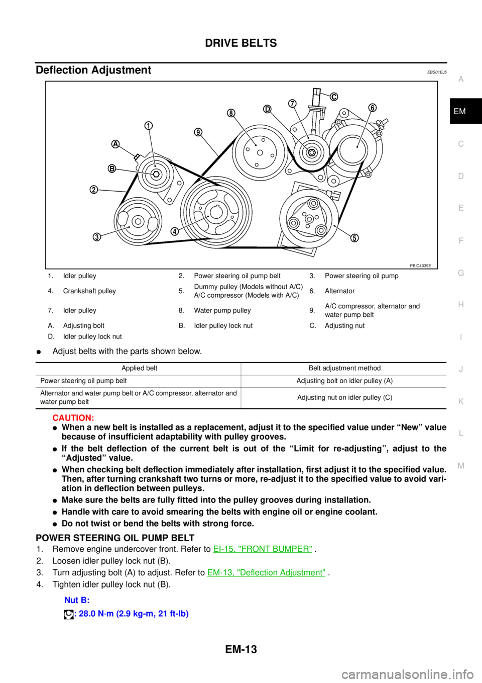
Deflection AdjustmentEBS01EJ5
lAdjust belts with the parts shown below.
CAUTION:
lWhen a new belt is installed as a replacement, adjust it to the specified value under “New” value
because of insufficient adaptability with pulley grooves.
lIf the belt deflection of the current belt is out of the “Limit for re-adjusting”, adjust to the
“Adjusted” value.
lWhen checking belt deflection immediately after installation, first adjust it to the specified value.
Then, after turning crankshaft two turns or more, re-adjust it to the specified value to avoid vari-
ation in deflection between pulleys.
lMake sure the belts are fully fitted into the pulley grooves during installation.
lHandle with care to avoid smearing the belts with engine oil or engine coolant.
lDo not twist or bend the belts with strong force.
POWER STEERING OIL PUMP BELT
1. Remove engine undercover front. Refer toEI-15, "FRONT BUMPER".
2. Loosen idler pulley lock nut (B).
3. Turn adjusting bolt (A) to adjust. Refer toEM-13, "
Deflection Adjustment".
4. Tighten idler pulley lock nut (B).
1. Idler pulley 2. Power steering oil pump belt 3. Power steering oil pump
4. Crankshaft pulley 5.Dummy pulley (Models without A/C)
A/C compressor (Models with A/C)6. Alternator
7. Idler pulley 8. Water pump pulley 9.A/C compressor, alternator and
water pump belt
A. Adjusting bolt B. Idler pulley lock nut C. Adjusting nut
D. Idler pulley lock nut
PBIC4039E
Applied belt Belt adjustment method
Power steering oil pump belt Adjusting bolt on idler pulley (A)
Alternator and water pump belt or A/C compressor, alternator and
water pump beltAdjusting nut on idler pulley (C)
Nut B:
: 28.0 N·m (2.9 kg-m, 21 ft-lb)