DISPOSAL OF AIR BAG MODULE AND SEAT BELT PRE-TENSIONER
SRS-53
C
D
E
F
G
I
J
K
L
MA
B
SRS
1. Cut the inflator from side curtain air bag module.
2. Connect deployment tool [SST: KV99106400] to the inflator
using deployment tool adapter [SST: KV99110500].
3. Put the inflator connected with the deployment tool [SST:
KV99106400] into a tire without a wheel.
4. Put the tire with the inflator onto another tire without wheel. Add
an additional tire without a wheel and then a tire mounted on a
wheel on top.
CAUTION:
Tie all tires together with a strap in order to keep them
standing.
5. Connect red clip of deployment tool to battery positive terminal
and black clip to negative terminal.
6. The lamp on the right side of the tool, marked “deployment tool
power”, should glow green, not red.
7. Press the button on the deployment tool. The left side lamp on
the tool, marked “air bag connector voltage”, will illuminate and the air bag module will deploy.
CAUTION:
When deploying the side curtain air bag module, stand at least 5 m (16 ft) away from the side cur-
tain air bag module.
8. Repeat this procedure to deploy the second inflator.
SHIA0198E
PHIA0568E
PHIA0011E
PHIA0555E
WHEEL
WT-3
C
D
F
G
H
I
J
K
L
MA
B
WT
WHEELPFP:40300
InspectionEES002L2
1. Check tires for wear and improper inflation.
2. Check wheels for deformation, cracks and other damage. If
deformed, remove wheel and check wheel runout.
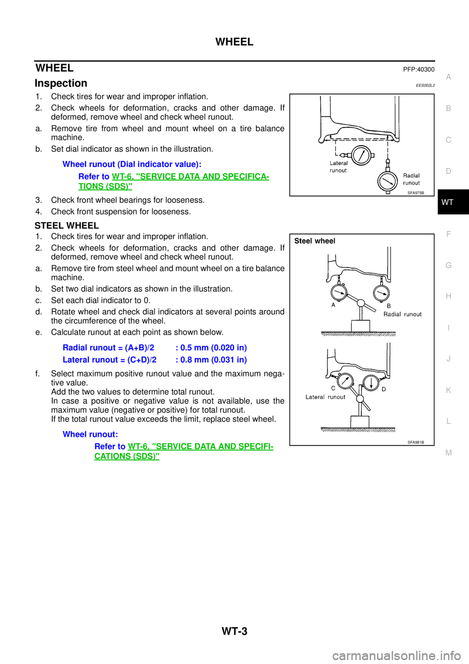
a. Remove tire from wheel and mount wheel on a tire balance
machine.
b. Set dial indicator as shown in the illustration.
3. Check front wheel bearings for looseness.
4. Check front suspension for looseness.
STEEL WHEEL
1. Check tires for wear and improper inflation.
2. Check wheels for deformation, cracks and other damage. If
deformed, remove wheel and check wheel runout.
a. Remove tire from steel wheel and mount wheel on a tire balance
machine.
b. Set two dial indicators as shown in the illustration.
c. Set each dial indicator to 0.
d. Rotate wheel and check dial indicators at several points around
the circumference of the wheel.
e. Calculate runout at each point as shown below.
f. Select maximum positive runout value and the maximum nega-
tive value.
Add the two values to determine total runout.
In case a positive or negative value is not available, use the
maximum value (negative or positive) for total runout.
If the total runout value exceeds the limit, replace steel wheel.Wheel runout (Dial indicator value):
Refer toWT-6, "
SERVICE DATA AND SPECIFICA-
TIONS (SDS)"SFA975B
Radial runout = (A+B)/2 : 0.5 mm (0.020 in)
Lateral runout = (C+D)/2 : 0.8 mm (0.031 in)
Wheel runout:
Refer toWT-6, "
SERVICE DATA AND SPECIFI-
CATIONS (SDS)"
SFA981B