2005 NISSAN NAVARA key battery
[x] Cancel search: key batteryPage 762 of 3171

BL-178
NATS(NISSAN ANTI-THEFT SYSTEM)
Trouble Diagnoses
EIS00DB0
SYMPTOM MATRIX CHART 1
Self-diagnosis related item
*1: When NATS detects trouble, the security indicator lights up while ignition key is in the “ON” position.
SYMPTOM MATRIX CHART 2
Non self-diagnosis related item
*: CONSULT-II self-diagnostic results display screen “no malfunction is detected”.SYMPTOMDisplayed “SELF-DIAG
RESULTS” on CON-
SULT-II screen.DIAGNOSTIC PROCE-
DURE
(Reference page)SYSTEM
(Malfunctioning part or mode)
lSecurity indicator
lighting up*1
lEngine cannot be
startedCHAIN OF ECM-IMMU
[P1612]PROCEDURE 1
(BL-179
)In rare case, “CHAIN OF ECM-IMMU” might be stored
during key registration procedure, even if the system is
not malfunctioning.
Open circuit in battery voltage line of BCM circuit
Open circuit in ignition line of BCM circuit
Open circuit in ground line of BCM circuit
Open or short circuit between BCM and ECM communi-
cation line
ECM
BCM
DIFFERENCE OF KEY
[P1615]PROCEDURE 2
(BL-181
)Unregistered key
BCM
CHAIN OF IMMU-KEY
[P1614]PROCEDURE 3
(BL-181
)Malfunction of key ID chip
Communication line between ANT/ AMP and BCM:
Open circuit or short circuit of battery voltage line or
ground line
Open circuit in power source line of ANT/ AMP circuit
Open circuit in ground line of ANT/ AMP circuit
NATS antenna amp.
BCM
ID DISCORD, IMM-
ECM
[P1611]PROCEDURE 4
(BL-184
)System initialization has not yet been completed.
ECM
ECM
[P1616]EC-269, "
DTC P1616
ECM"ECM
lSecurity indicator
lighting up*1
lEngine cannot be
startedLOCK MODE
[P1610]PROCEDURE 6
(BL-187)When the starting operation is carried out five or more
times consecutively under the following conditions, NATS
will shift the mode to one which prevents the engine from
being started.
lUnregistered ignition key is used.
lBCM or ECM’s malfunctioning.
Security indicator
lighting up*
1
DON'T ERASE
BEFORE CHECKING
ENG DIAGWORK FLOW
(BL-177
)Engine trouble data and NATS trouble data have been
detected in ECM
SYMPTOMDIAGNOSTIC PROCEDURE
(Reference page)SYSTEM
(Malfunctioning part or mode)
Security indicator does not light up*.PROCEDURE 5
(BL-185
)Security indictor.
Open circuit between Fuse and BCM
BCM
Page 763 of 3171
NATS(NISSAN ANTI-THEFT SYSTEM)
BL-179
C
D
E
F
G
H
J
K
L
MA
B
BL
Diagnostic Procedure 1EIS00DB1
Self-diagnostic results:
“CHAIN OF ECM-IMMU” displayed on CONSULT-II screen
First perform the “SELF-DIAG RESULTS” in “BCM” with CONSULT-II, then perform the trouble diagno-
sis of malfunction system indicated “SELF-DIAG RESULTS” of “BCM”. Refer toBCS-16, "
CAN Com-
munication Inspection Using CONSULT-II (Self-Diagnosis)".
1.CONFIRM SELF-DIAGNOSTIC RESULTS
Confirm SELF-DIAGNOSTIC RESULTS “CHAIN OF ECM-IMMU”
displayed on CONSULT-II screen.
NOTE:
In rare case, “CHAIN OF ECM-IMMU” might be stored during key
registration procedure, even if the system is not malfunctioning.
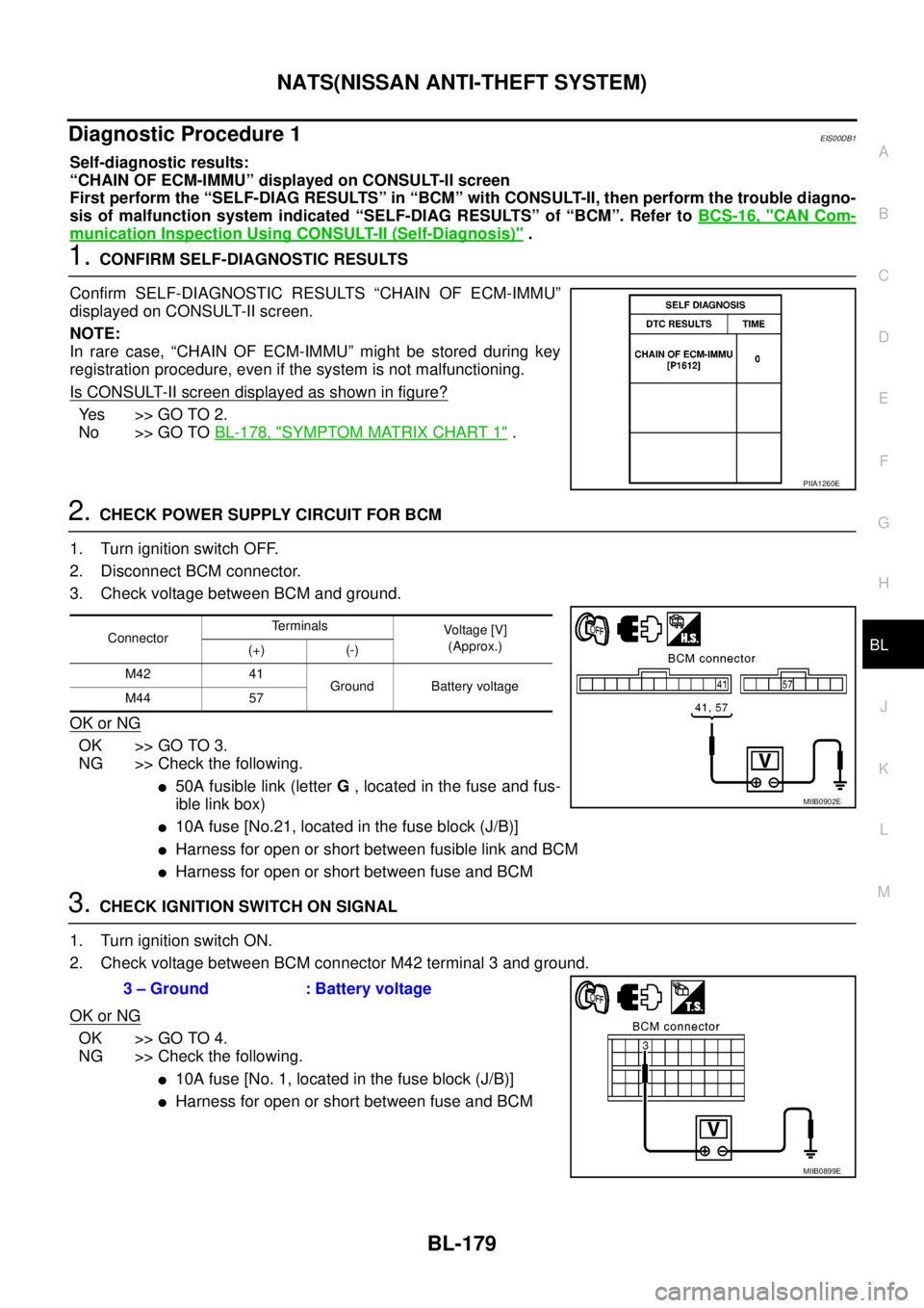
Is CONSULT-II screen displayed as shown in figure?
Ye s > > G O T O 2 .
No >> GO TOBL-178, "
SYMPTOM MATRIX CHART 1".
2.CHECK POWER SUPPLY CIRCUIT FOR BCM
1. Turn ignition switch OFF.
2. Disconnect BCM connector.
3. Check voltage between BCM and ground.
OK or NG
OK >> GO TO 3.
NG >> Check the following.
l50A fusible link (letterG, located in the fuse and fus-
ible link box)
l10A fuse [No.21, located in the fuse block (J/B)]
lHarness for open or short between fusible link and BCM
lHarness for open or short between fuse and BCM
3.CHECK IGNITION SWITCH ON SIGNAL
1. Turn ignition switch ON.
2. Check voltage between BCM connector M42 terminal 3 and ground.
OK or NG
OK >> GO TO 4.
NG >> Check the following.
l10A fuse [No. 1, located in the fuse block (J/B)]
lHarness for open or short between fuse and BCM
PIIA1260E
ConnectorTerminals
Voltag e [V]
(Approx.)
(+) (-)
M42 41
Ground Battery voltage
M44 57
MIIB0902E
3 – Ground : Battery voltage
MIIB0899E
Page 766 of 3171
BL-182
NATS(NISSAN ANTI-THEFT SYSTEM)
3.CHECK NATS IGNITION KEY ID CHIP
Start engine with another registered NATS ignition key.
Doestheenginestart?
Yes >> Ignition key ID chip is malfunctioning.
lReplace the ignition key
lPerform initialization with CONSULT-II
For initialization, refer to “CONSULT-II Operation Manual NATS”
No >> GO TO 4.
4.CHECK POWER SUPPLY FOR NATS ANTENNA AMP.
1. Turn ignition switch “OFF”.
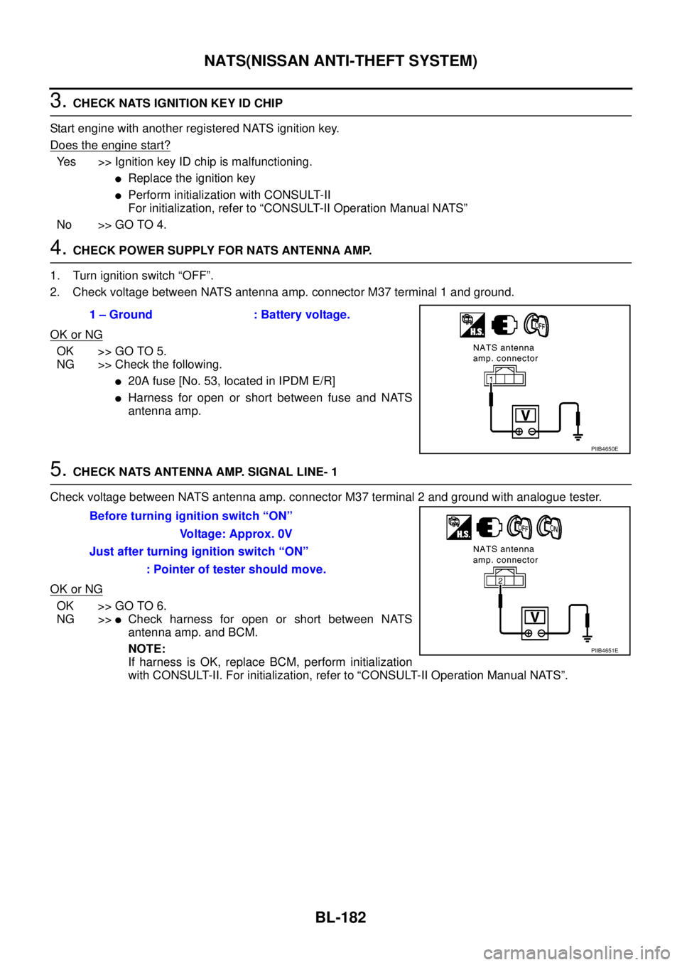
2. Check voltage between NATS antenna amp. connector M37 terminal 1 and ground.
OK or NG
OK >> GO TO 5.
NG >> Check the following.
l20A fuse [No. 53, located in IPDM E/R]
lHarness for open or short between fuse and NATS
antenna amp.
5.CHECK NATS ANTENNA AMP. SIGNAL LINE- 1
Check voltage between NATS antenna amp. connector M37 terminal 2 and ground with analogue tester.
OK or NG
OK >> GO TO 6.
NG >>
lCheck harness for open or short between NATS
antenna amp. and BCM.
NOTE:
If harness is OK, replace BCM, perform initialization
with CONSULT-II. For initialization, refer to “CONSULT-II Operation Manual NATS”. 1 – Ground : Battery voltage.
PIIB4650E
Before turning ignition switch “ON”
Voltage: Approx. 0V
Just after turning ignition switch “ON”
: Pointer of tester should move.
PIIB4651E
Page 772 of 3171
BL-188
NATS(NISSAN ANTI-THEFT SYSTEM)
4.PERFORM INITIALIZATION WITH CONSULT-II AGAIN
1. Replace BCM.
2. Perform initialization with CONSULT-II.
For initialization, refer to “CONSULT-II Operation Manual
NATS”.
NOTE:
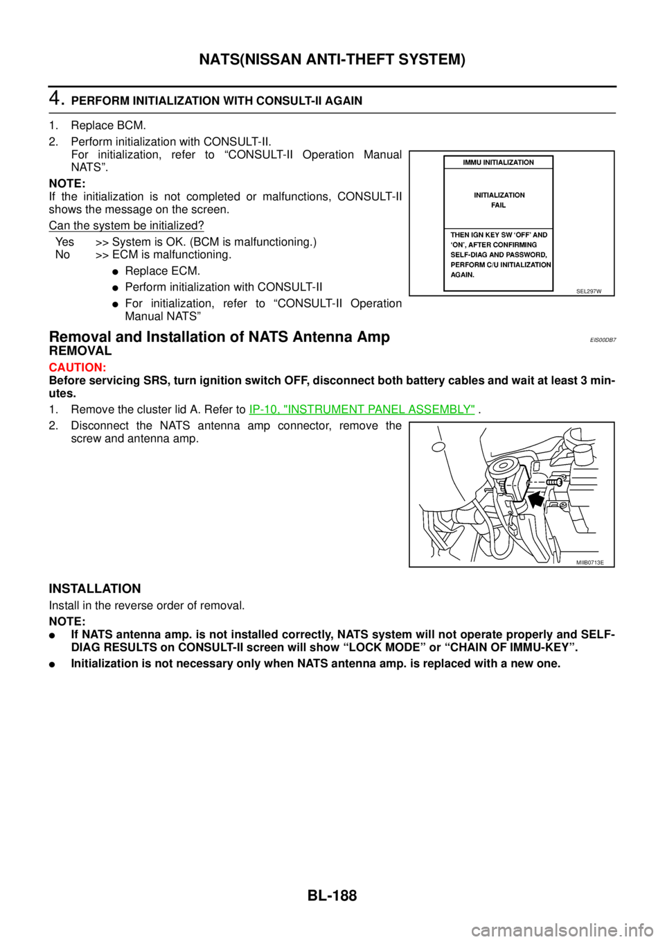
If the initialization is not completed or malfunctions, CONSULT-II
shows the message on the screen.
Can the system be initialized?
Yes >>SystemisOK.(BCMismalfunctioning.)
No >> ECM is malfunctioning.
lReplace ECM.
lPerform initialization with CONSULT-II
lFor initialization, refer to “CONSULT-II Operation
Manual NATS”
Removal and Installation of NATS Antenna AmpEIS00DB7
REMOVAL
CAUTION:
Before servicing SRS, turn ignition switch OFF, disconnect both battery cables and wait at least 3 min-
utes.
1. Remove the cluster lid A. Refer toIP-10, "
INSTRUMENT PANEL ASSEMBLY".
2. Disconnect the NATS antenna amp connector, remove the
screw and antenna amp.
INSTALLATION
Install in the reverse order of removal.
NOTE:
lIf NATS antenna amp. is not installed correctly, NATS system will not operate properly and SELF-
DIAG RESULTS on CONSULT-II screen will show “LOCK MODE” or “CHAIN OF IMMU-KEY”.
lInitialization is not necessary only when NATS antenna amp. is replaced with a new one.
SEL297W
MIIB0713E
Page 971 of 3171
WARNING CHIME
DI-61
C
D
E
F
G
H
I
J
L
MA
B
DI
SYMPTOM CHART
Meter Buzzer Circuit InspectionEKS00L9L
1.CHECK CHIME OPERATION
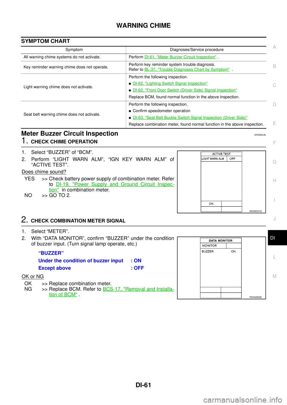
1. Select “BUZZER” of “BCM”.
2. Perform “LIGHT WARN ALM”, “IGN KEY WARN ALM” of
“ACTIVE TEST”.
Does chime sound?
YES >> Check battery power supply of combination meter. Refer
toDI-19, "
Power Supply and Ground Circuit Inspec-
tion"in combination meter.
NO >> GO TO 2.
2.CHECK COMBINATION METER SIGNAL
1. Select “METER”.
2. With “DATA MONITOR”, confirm “BUZZER” under the condition
of buzzer input. (Turn signal lamp operate, etc.)
OK or NG
OK >> Replace combination meter.
NG >> Replace BCM. Refer toBCS-17, "
Removal and Installa-
tion of BCM".
Symptom Diagnoses/Service procedure
All warning chime systems do not activate. PerformDI-61, "
Meter Buzzer Circuit Inspection".
Key reminder warning chime does not operate.Perform key reminder system trouble diagnosis.
Refer toBL-37, "
Trouble Diagnoses Chart by Symptom".
Light warning chime does not activate.Perform the following inspection.
lDI-62, "Lighting Switch Signal Inspection"
lDI-62, "Front Door Switch (Driver Side) Signal Inspection"
Replace BCM, found normal function in the above inspection.
Seat belt warning chime does not activate.Perform the following inspection.
lConfirm speedometer operation
lDI-63, "Seat Belt Buckle Switch Signal Inspection (Driver Side)"
Replace combination meter, found normal function in the above inspection.
SKIA6331E
“BUZZER”
Under the condition of buzzer input : ON
Except above : OFF
PKIA2063E
Page 1008 of 3171
EC-28
ON BOARD DIAGNOSTIC (OBD) SYSTEM
lIf the battery is disconnected, the emission-related diagnostic information will be lost within 24
hours.
lThe following data are cleared when the ECM memory is erased.
–Diagnostic trouble codes
–Freeze frame data
–Fuel pump learning value
Actual work procedures are explained using a DTC as an example. Be careful so that not only the DTC, but all
of the data listed above, are cleared from the ECM memory during work procedures.
Freeze Frame DataEBS01KCP
The ECM records the driving conditions such as calculated load value, engine coolant temperature, engine
speed, vehicle speed and intake manifold pressure at the moment a malfunction is detected.
The data, stored together with the DTC data, are called freeze frame data and displayed on CONSULT-II. For
details, seeEC-28, "
Freeze Frame Data".
Only one set of freeze frame data can be stored in the ECM. If freeze frame data is stored in the ECM memory
and another freeze frame data occurs later, the first (original) freeze frame data remains unchanged in the
ECM memory.
Freeze frame data (along with the DTCs) are cleared when the ECM memory is erased. Procedures for clear-
ing the ECM memory are described inEC-27, "
HOW TO ERASE DTC".
NATS (Nissan Anti-theft System)EBS01KCQ
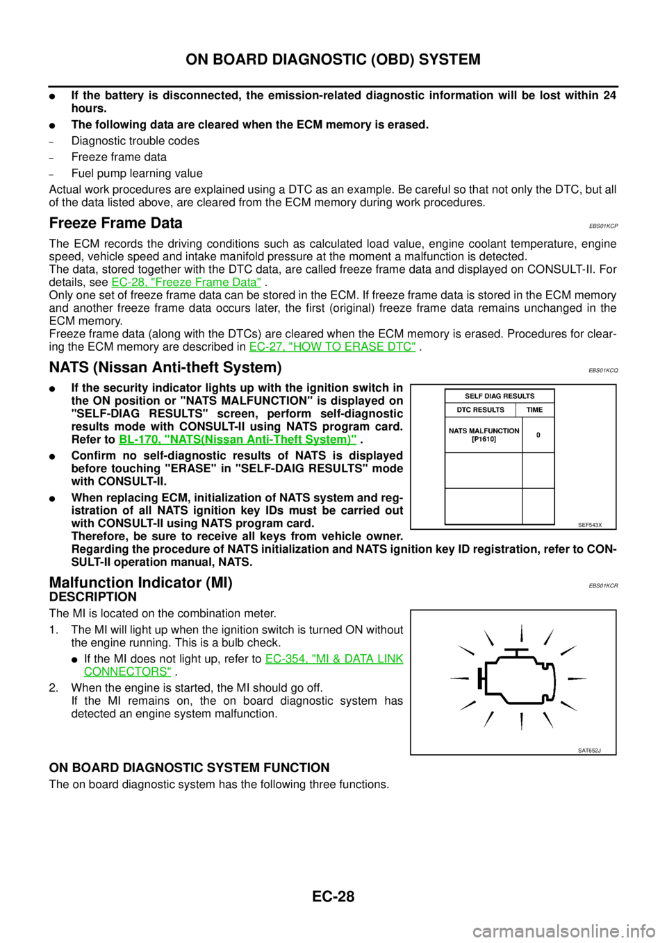
lIf the security indicator lights up with the ignition switch in
the ON position or "NATS MALFUNCTION" is displayed on
"SELF-DIAG RESULTS" screen, perform self-diagnostic
results mode with CONSULT-II using NATS program card.
Refer toBL-170, "
NATS(Nissan Anti-Theft System)".
lConfirm no self-diagnostic results of NATS is displayed
before touching "ERASE" in "SELF-DAIG RESULTS" mode
with CONSULT-II.
lWhen replacing ECM, initialization of NATS system and reg-
istration of all NATS ignition key IDs must be carried out
with CONSULT-II using NATS program card.
Therefore, be sure to receive all keys from vehicle owner.
Regarding the procedure of NATS initialization and NATS ignition key ID registration, refer to CON-
SULT-II operation manual, NATS.
Malfunction Indicator (MI)EBS01KCR
DESCRIPTION
The MI is located on the combination meter.
1. The MI will light up when the ignition switch is turned ON without
the engine running. This is a bulb check.
lIf the MI does not light up, refer toEC-354, "MI&DATA LINK
CONNECTORS".
2. When the engine is started, the MI should go off.
If the MI remains on, the on board diagnostic system has
detected an engine system malfunction.
ON BOARD DIAGNOSTIC SYSTEM FUNCTION
The on board diagnostic system has the following three functions.
SEF543X
SAT652J
Page 1184 of 3171
EC-204
DTC P0563 BATTERY VOLTAGE
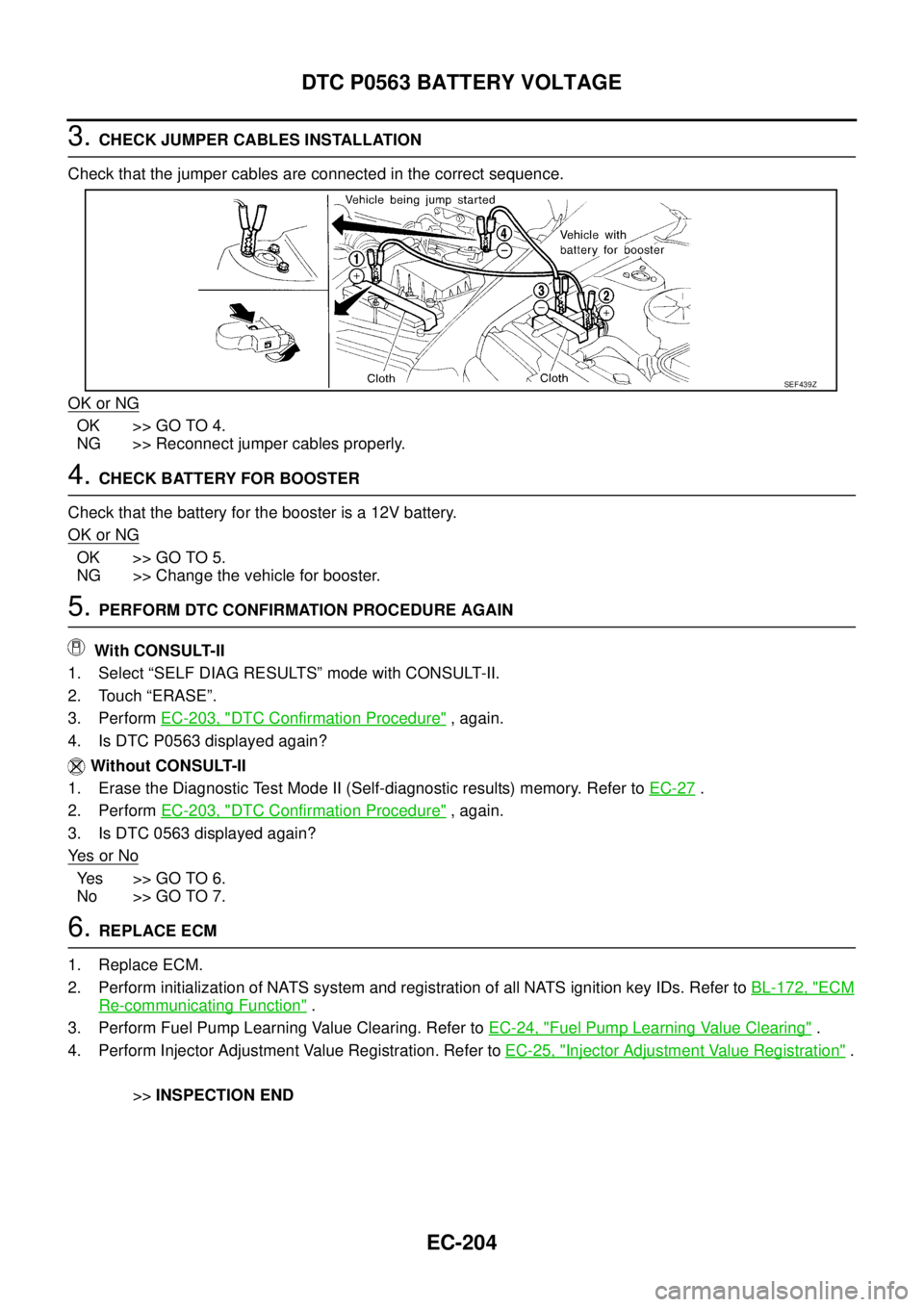
3.CHECK JUMPER CABLES INSTALLATION
Check that the jumper cables are connected in the correct sequence.
OK or NG
OK >> GO TO 4.
NG >> Reconnect jumper cables properly.
4.CHECK BATTERY FOR BOOSTER
Check that the battery for the booster is a 12V battery.
OK or NG
OK >> GO TO 5.
NG >> Change the vehicle for booster.
5.PERFORM DTC CONFIRMATION PROCEDURE AGAIN
With CONSULT-II
1. Select “SELF DIAG RESULTS” mode with CONSULT-II.
2. Touch “ERASE”.
3. PerformEC-203, "
DTC Confirmation Procedure",again.
4. Is DTC P0563 displayed again?
Without CONSULT-II
1. Erase the Diagnostic Test Mode II (Self-diagnostic results) memory. Refer toEC-27
.
2. PerformEC-203, "
DTC Confirmation Procedure",again.
3. Is DTC 0563 displayed again?
Ye s o r N o
Yes >>GOTO6.
No >> GO TO 7.
6.REPLACE ECM
1. Replace ECM.
2. Perform initialization of NATS system and registration of all NATS ignition key IDs. Refer toBL-172, "
ECM
Re-communicating Function".
3. Perform Fuel Pump Learning Value Clearing. Refer toEC-24, "
Fuel Pump Learning Value Clearing".
4. Perform Injector Adjustment Value Registration. Refer toEC-25, "
Injector Adjustment Value Registration".
>>INSPECTION END
SEF439Z
Page 1623 of 3171

GI-1
GENERAL INFORMATION
A GENERAL INFORMATION
CONTENTS
C
D
E
F
G
H
I
J
K
L
MB
GI
SECTIONGI
GENERAL INFORMATION
PRECAUTIONS .......................................................... 3
Description ............................................................... 3
Precautions for Supplemental Restraint System
(SRS)“AIRBAG”and“SEATBELTPRE-TEN-
SIONER” .................................................................. 3
Precautions for NATS (NISSAN ANTI-THEFT SYS-
TEM) ........................................................................ 3
Precautions Necessary for Steering Wheel Rotation
After Battery Disconnect .......................................... 3
OPERATION PROCEDURE ................................. 4
General Precautions ................................................ 4
Precautions for Three Way Catalyst ......................... 5
Precautions for Fuel ................................................. 5
GASOLINE ENGINE ............................................. 5
DIESEL ENGINE ................................................... 6
Precautions for Multiport Fuel Injection System or
Engine Control System ............................................ 6
Precautions for Turbocharger (If Equipped) ............. 6
Precautions for Hoses .............................................. 6
HOSE REMOVAL AND INSTALLATION ............... 6
HOSE CLAMPING ................................................ 7
Precautions for Engine Oils ...................................... 7
HEALTH PROTECTION PRECAUTIONS ............. 7
ENVIRONMENTAL PROTECTION PRECAU-
TIONS ................................................................... 8
Precautions for Air Conditioning ............................... 8
HOW TO USE THIS MANUAL ................................... 9
Description ............................................................... 9
Terms ....................................................................... 9
Units ......................................................................... 9
Contents ................................................................... 9
Components ........................................................... 10
SYMBOLS ........................................................... 10
How to Follow Trouble Diagnoses ........................... 11
DESCRIPTION ..................................................... 11
HOW TO FOLLOW TEST GROUPS IN TROU-
BLE DIAGNOSES ................................................ 11
HARNESS WIRE COLOR AND CONNECTOR
NUMBER INDICATION ....................................... 12
KEY TO SYMBOLS SIGNIFYING MEASURE-MENTS OR PROCEDURES ............................... 13
How to Read Wiring Diagrams ............................... 15
CONNECTOR SYMBOLS ................................... 15
SAMPLE/WIRING DIAGRAM - EXAMPL - .......... 16
DESCRIPTION .................................................... 17
Abbreviations .......................................................... 23
SERVICE INFORMATION FOR ELECTRICAL INCI-
DENT ......................................................................... 24
How to Perform Efficient Diagnosis for an Electrical
Incident ................................................................... 24
WORK FLOW ...................................................... 24
INCIDENT SIMULATION TESTS ........................ 24
CIRCUIT INSPECTION ....................................... 27
Control Units and Electrical Parts ........................... 32
PRECAUTIONS .................................................. 32
CONTROL UNIT CONFIGURATION PROCEDURE... 34
Description .............................................................. 34
Part Replacement procedure Reference Table ...... 34
Work Procedure ...................................................... 36
Configuration (BCM) ............................................... 37
DESCRIPTION .................................................... 37
READ CONFIGURATION PROCEDURE ............ 37
WRITE CONFIGURATION PROCEDURE .......... 41
CONSULT-II CHECKING SYSTEM .......................... 47
Description .............................................................. 47
Function and System Application ........................... 47
Nickel Metal Hydride Battery Replacement ............ 48
Checking Equipment .............................................. 49
CONSULT-II Start Procedure .................................. 49
CONSULT-II Data Link Connector (DLC) Circuit .... 50
INSPECTION PROCEDURE .............................. 51
LIFTING POINT ......................................................... 52
Pantograph Jack, Garage Jack and Safety Stand... 52
2-Pole Lift ............................................................... 52
TOW TRUCK TOWING ............................................. 53
Tow Truck Towing ................................................... 53
4X2 MODEL ........................................................ 53
4X4 MODEL ........................................................ 54
TOWING POINT .................................................. 54
Vehicle Recovery (Freeing a Stuck Vehicle) ........... 54