2005 NISSAN NAVARA sun sensor
[x] Cancel search: sun sensorPage 12 of 3171

AT-4
Sensor 2 ...............................................................218
Parking Components (2WD Models Only) ............230
Rear Oil Seal ........................................................237
Revolution Sensor Components (2WD Models
Only) .....................................................................238
AIR BREATHER HOSE ...........................................243
Removal and Installation ......................................243
A/T FLUID COOLER ...............................................244
Removal and Installation ......................................244
TRANSMISSION ASSEMBLY ................................247
Removal and Installation ......................................247
OVERHAUL .............................................................251
Components .........................................................251
Oil Channel ...........................................................259
Locations of Adjusting Shims, Needle Bearings,
Thrust Washers and Snap Rings ..........................261
DISASSEMBLY .......................................................263
Disassembly .........................................................263
REPAIR FOR COMPONENT PARTS ......................281
Oil Pump ...............................................................281
Front Sun Gear, 3rd One-way Clutch ...................284Front Carrier, Input Clutch, Rear Internal Gear .....286
Mid Sun Gear, Rear Sun Gear, High and Low
Reverse Clutch Hub ..............................................291
High and Low Reverse Clutch ..............................296
Direct Clutch .........................................................298
ASSEMBLY .............................................................300
Assembly (1) .........................................................300
Adjustment ............................................................313
Assembly (2) .........................................................316
SERVICE DATA AND SPECIFICATIONS (SDS) ....323
General Specifications ..........................................323
Stall Speed ............................................................323
Line Pressure ........................................................323
Vehicle Speed at Which Gear Shifting Occurs ......324
Vehicle Speed at Which Lock-Up Occurs/Releases.324
A/T Fluid Temperature Sensor ..............................324
Vehicle Speed Sensor A/T (Revolution Sensor) ...325
Turbine Revolution Sensor ....................................325
Reverse Brake ......................................................325
Total End Play .......................................................325
Page 91 of 3171

TROUBLE DIAGNOSIS
AT-83
D
E
F
G
H
I
J
K
L
MA
B
AT
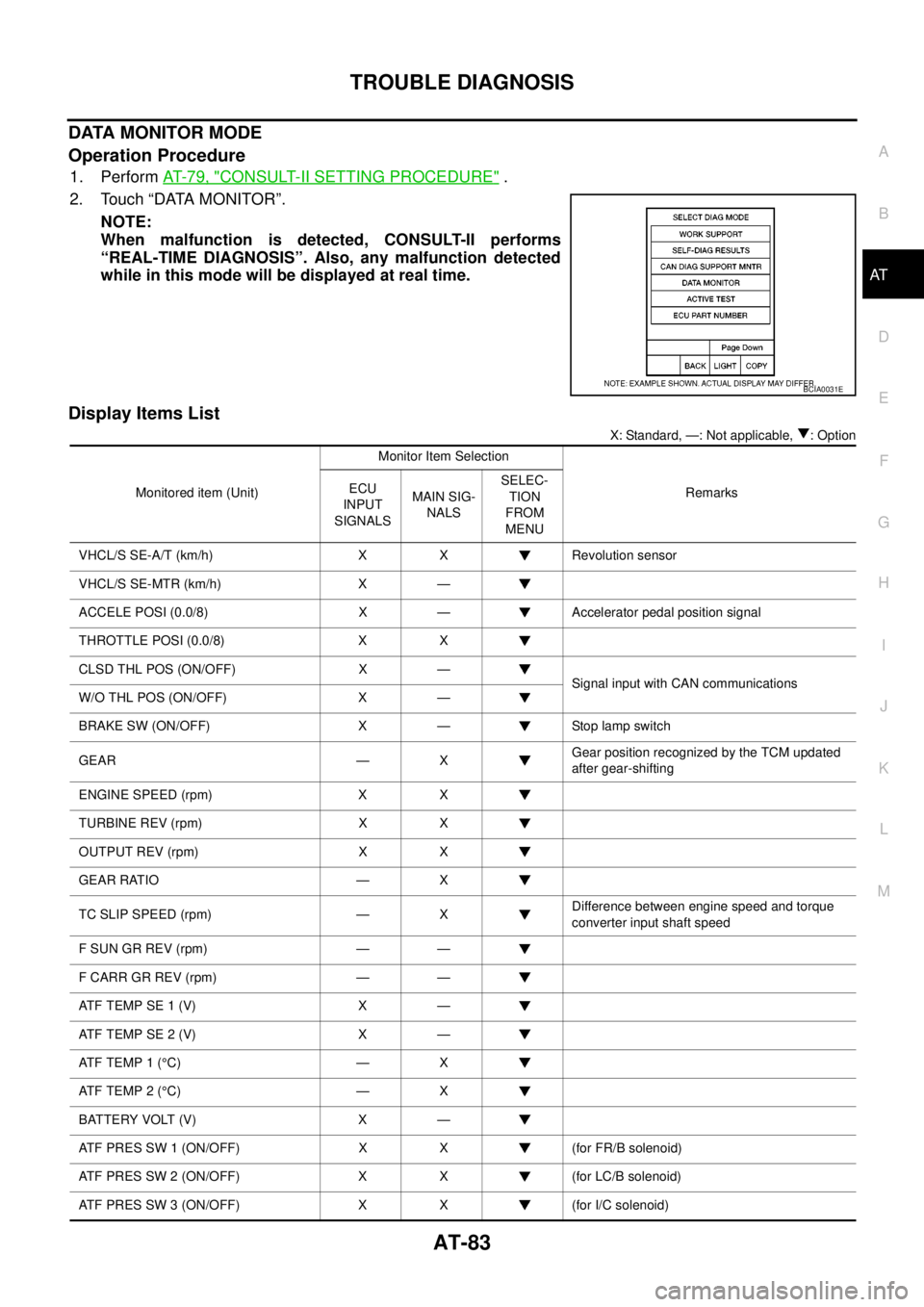
DATA MONITOR MODE
Operation Procedure
1. PerformAT-79, "CONSULT-II SETTING PROCEDURE".
2. Touch “DATA MONITOR”.
NOTE:
When malfunction is detected, CONSULT-II performs
“REAL-TIME DIAGNOSIS”. Also, any malfunction detected
while in this mode will be displayed at real time.
Display Items List
X: Standard, —: Not applicable, : Option
BCIA0031E
Monitored item (Unit)Monitor Item Selection
Remarks ECU
INPUT
SIGNALSMAIN SIG-
NALSSELEC-
TION
FROM
MENU
VHCL/S SE-A/T (km/h) X X Revolution sensor
VHCL/S SE-MTR (km/h) X —
ACCELE POSI (0.0/8) X — Accelerator pedal position signal
THROTTLE POSI (0.0/8) X X
CLSD THL POS (ON/OFF) X —
Signal input with CAN communications
W/O THL POS (ON/OFF) X —
BRAKE SW (ON/OFF) X — Stop lamp switch
GEAR — XGear position recognized by the TCM updated
after gear-shifting
ENGINE SPEED (rpm) X X
TURBINE REV (rpm) X X
OUTPUT REV (rpm) X X
GEAR RATIO — X
TC SLIP SPEED (rpm) — XDifference between engine speed and torque
converter input shaft speed
F SUN GR REV (rpm) — —
F CARR GR REV (rpm) — —
ATFTEMPSE1(V) X —
ATFTEMPSE2(V) X —
AT F T E M P 1 (°C) — X
AT F T E M P 2 (°C) — X
BATTERY VOLT (V) X —
ATF PRES SW 1 (ON/OFF) X X (for FR/B solenoid)
ATF PRES SW 2 (ON/OFF) X X (for LC/B solenoid)
ATF PRES SW 3 (ON/OFF) X X (for I/C solenoid)
Page 336 of 3171

ATC-2
DATA MONITOR .................................................. 34
How to Perform Trouble Diagnosis for Quick and
Accurate Repair ...................................................... 35
WORK FLOW ...................................................... 35
SYMPTOM TABLE .............................................. 35
Component Parts and Harness Connector Location... 36
ENGINE COMPARTMENT .................................. 36
FRONT PASSENGER COMPARTMENT ............ 37
Schematic —LHD MODELS— ............................... 38
Wiring Diagram —A/C— —LHD MODELS— ......... 39
Schematic —RHD MODELS— ............................... 46
Wiring Diadram —A/C— —RHD MODELS— ......... 47
Front Air Control Terminals and Reference Value... 53
PIN CONNECTOR TERMINAL LAYOUT ............ 53
TERMINALS AND REFERENCE VALUE FOR
FRONT AIR CONTROL ....................................... 53
A/C System Self-diagnosis Function ...................... 55
DESCRIPTION .................................................... 55
Operational Check .................................................. 57
CHECKING MEMORY FUNCTION ..................... 57
CHECKING BLOWER ......................................... 57
CHECKING DISCHARGE AIR ............................ 58
CHECKING RECIRCULATION ............................ 58
CHECKING TEMPERATURE DECREASE ......... 58
CHECKING TEMPERATURE INCREASE .......... 59
CHECK A/C SWITCH .......................................... 59
CHECKING AUTO MODE ................................... 59
Power Supply and Ground Circuit for Front Air Con-
trol ........................................................................... 60
INSPECTION FLOW ........................................... 60
COMPONENT DESCRIPTION ............................ 61
DIAGNOSTIC PROCEDURE FOR A/C SYSTEM... 61
Mode Door Motor Circuit ........................................ 63
INSPECTION FLOW ........................................... 63
SYSTEM DESCRIPTION .................................... 64
COMPONENT DESCRIPTION ............................ 65
DIAGNOSTIC PROCEDURE FOR MODE
DOOR MOTOR ................................................... 65
Air Mix Door Motor Circuit ...................................... 68
INSPECTION FLOW ........................................... 68
SYSTEM DESCRIPTION .................................... 69
COMPONENT DESCRIPTION ............................ 70
DIAGNOSTIC PROCEDURE FOR AIR MIX
DOOR MOTOR (DRIVER) ................................... 71
DIAGNOSTIC PROCEDURE FOR AIR MIX
DOOR MOTOR (PASSENGER) .......................... 73
Intake Door Motor Circuit ........................................ 77
INSPECTION FLOW ........................................... 77
SYSTEM DESCRIPTION .................................... 78
COMPONENT DESCRIPTION ............................ 79
DIAGNOSTIC PROCEDURE FOR INTAKE
DOOR MOTOR ................................................... 79
Blower Motor Circuit ............................................... 80
INSPECTION FLOW ........................................... 80
SYSTEM DESCRIPTION .................................... 81
COMPONENT DESCRIPTION ............................ 82
DIAGNOSTIC PROCEDURE FOR BLOWER
MOTOR ............................................................... 82
COMPONENT INSPECTION .............................. 86Magnet Clutch Circuit .............................................. 87
INSPECTION FLOW ............................................ 87
SYSTEM DESCRIPTION ..................................... 88
DIAGNOSTIC PROCEDURE FOR MAGNET
CLUTCH .............................................................. 88
COMPONENT INSPECTION ............................... 92
Insufficient Cooling .................................................. 93
INSPECTION FLOW ............................................ 93
PERFORMANCE TEST DIAGNOSES ................ 94
PERFORMANCE CHART .................................... 96
TROUBLE DIAGNOSES FOR UNUSUAL PRES-
SURE ................................................................... 97
Insufficient Heating ...............................................100
INSPECTION FLOW ..........................................100
Noise .....................................................................101
INSPECTION FLOW ..........................................101
Self-diagnosis .......................................................103
INSPECTION FLOW ..........................................103
Memory Function ..................................................104
INSPECTION FLOW ..........................................104
Ambient Sensor Circuit .........................................105
COMPONENT DESCRIPTION ..........................105
AMBIENT TEMPERATURE INPUT PROCESS.105
DIAGNOSTIC PROCEDURE FOR AMBIENT
SENSOR ............................................................105
COMPONENT INSPECTION .............................107
In-vehicle Sensor Circuit .......................................108
COMPONENT DESCRIPTION ..........................108
DIAGNOSTIC PROCEDURE FOR IN-VEHICLE
SENSOR ............................................................109
COMPONENT INSPECTION ............................. 111
Optical Sensor Circuit ...........................................112
COMPONENT DESCRIPTION ..........................112
OPTICAL INPUT PROCESS .............................112
DIAGNOSTIC PROCEDURE FOR SUNLOAD
SENSOR ............................................................112
Intake Sensor Circuit .............................................114
COMPONENT DESCRIPTION ..........................114
DIAGNOSTIC PROCEDURE FOR INTAKE SEN-
SOR ...................................................................114
COMPONENT INSPECTION .............................115
CONTROL UNIT ......................................................116
Removal and Installation .......................................116
REMOVAL ..........................................................116
INSTALLATION ..................................................116
AMBIENT SENSOR ................................................117
Removal and Installation .......................................117
REMOVAL ..........................................................117
INSTALLATION ..................................................117
IN-VEHICLE SENSOR ............................................118
Removal and Installation .......................................118
REMOVAL ..........................................................118
INSTALLATION ..................................................118
OPTICAL SENSOR .................................................119
Removal and Installation .......................................119
INTAKE SENSOR ....................................................120
Removal and Installation .......................................120
REMOVAL ..........................................................120
INSTALLATION ..................................................120
Page 360 of 3171

ATC-26
AIR CONDITIONER CONTROL
AIR CONDITIONER CONTROL
PFP:27500
DescriptionEJS006B0
The front air control provides automatic regulation of the vehicle's interior temperature. The system is based
on the driver's and passenger's selected “set temperature”, regardless of the outside temperature changes.
This is done by utilizing a microcomputer, also referred to as the front air control, which receives input signals
from the following six sensors:
lAmbient sensor
lIn-vehicle sensor
lIntake sensor
lOptical sensor (one sensor for driver and passenger side)
lPBR (Position Balanced Resistor).
lVehicle speed sensor
The front air control uses these signals (including the set temperature) to automatically control:
lOutlet air volume
lAir temperature
lAir distribution
The front air control is used to select:
lOutlet air volume
lAir temperature/distribution
OperationEJS006B1
AIR MIX DOORS CONTROL
The air mix doors are automatically controlled so that in-vehicle temperature is maintained at a predetermined
value by the temperature setting, ambient temperature, in-vehicle temperature and amount of sunload.
BLOWER SPEED CONTROL
Blower speed is automatically controlled by the temperature setting, ambient temperature, in-vehicle tempera-
ture, intake temperature, amount of sunload and air mix door position.
When AUTO switch is pressed, the blower motor starts to gradually increase air flow volume (if required).
When engine coolant temperature is low, the blower motor operation is delayed to prevent cool air from flow-
ing.
INTAKE DOOR CONTROL
The intake door is automatically controlled by the temperature setting, ambient temperature, in-vehicle tem-
perature, intake temperature, amount of sunload and the ON-OFF operation of the compressor.
MODE DOOR CONTROL
The mode door is automatically controlled by the temperature setting, ambient temperature, in-vehicle temper-
ature, intake temperature and amount of sunload.
DEFROSTER DOOR CONTROL
The defroster door is controlled by: Turning the defroster dial to front defroster.
Page 446 of 3171

ATC-112
TROUBLE DIAGNOSIS
Optical Sensor Circuit
EJS006BY
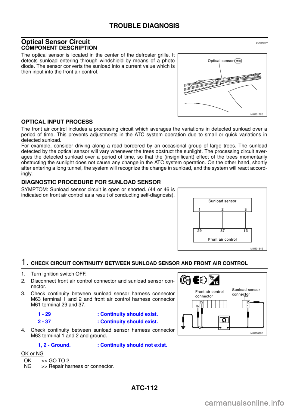
COMPONENT DESCRIPTION
The optical sensor is located in the center of the defroster grille. It
detects sunload entering through windshield by means of a photo
diode. The sensor converts the sunload into a current value which is
then input into the front air control.
OPTICAL INPUT PROCESS
The front air control includes a processing circuit which averages the variations in detected sunload over a
period of time. This prevents adjustments in the ATC system operation due to small or quick variations in
detected sunload.
For example, consider driving along a road bordered by an occasional group of large trees. The sunload
detected by the optical sensor will vary whenever the trees obstruct the sunlight. The processing circuit aver-
ages the detected sunload over a period of time, so that the (insignificant) effect of the trees momentarily
obstructing the sunlight does not cause any change in the ATC system operation. On the other hand, shortly
after entering a long tunnel, the system will recognize the change in sunload, and the system will react accord-
ingly.
DIAGNOSTIC PROCEDURE FOR SUNLOAD SENSOR
SYMPTOM: Sunload sensor circuit is open or shorted. (44 or 46 is
indicated on front air control as a result of conducting self-diagnosis).
1.CHECK CIRCUIT CONTINUITY BETWEEN SUNLOAD SENSOR AND FRONT AIR CONTROL
1. Turn ignition switch OFF.
2. Disconnect front air control connector and sunload sensor con-
nector.
3. Check continuity between sunload sensor harness connector
M63 terminal 1 and 2 and front air control harness connector
M61 terminal 29 and 37.
4. Check continuity between sunload sensor harness connector
M63 terminal 1 and 2 and ground.
OK or NG
OK >> GO TO 2.
NG >> Repair harness or connector.
MJIB0172E
MJIB0181E
1 - 29 : Continuity should exist.
2 - 37 : Continuity should exist.
1, 2 - Ground. : Continuity should not exist.
MJIB0086E
Page 447 of 3171

TROUBLE DIAGNOSIS
ATC-113
C
D
E
F
G
H
I
K
L
MA
B
AT C
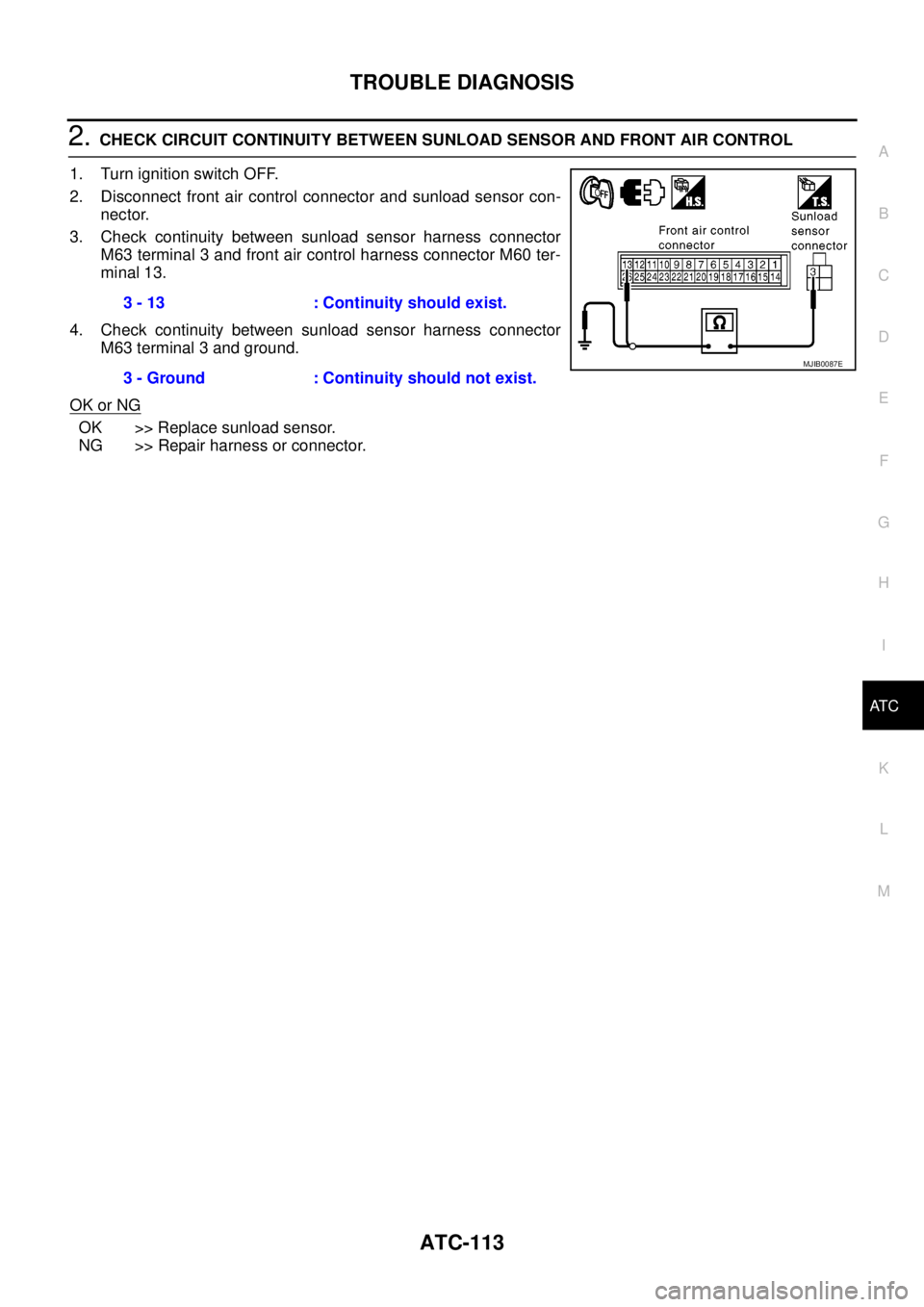
2.CHECK CIRCUIT CONTINUITY BETWEEN SUNLOAD SENSOR AND FRONT AIR CONTROL
1. Turn ignition switch OFF.
2. Disconnect front air control connector and sunload sensor con-
nector.
3. Check continuity between sunload sensor harness connector
M63 terminal 3 and front air control harness connector M60 ter-
minal 13.
4. Check continuity between sunload sensor harness connector
M63 terminal 3 and ground.
OK or NG
OK >> Replace sunload sensor.
NG >> Repair harness or connector.3 - 13 : Continuity should exist.
3 - Ground : Continuity should not exist.
MJIB0087E
Page 484 of 3171

ATC-150
REFRIGERANT LINES
CAUTION:
Replace the O-rings on the A/C low-pressure flexible A/C hose and the high-pressure A/C pipe with
new ones. Apply compressor oil to the O-rings for installation.
Removal and Installation for Expansion ValveEJS006CZ
REMOVAL
1. Discharge the refrigerant. Refer toATC-138, "HFC-134a (R-134a) Service Procedure".
2. Remove the heater and cooling unit assembly. Refer toATC-126, "
REMOVAL".
3. Remove the heater core and evaporator pipes grommet.
4. Remove the expansion valve.
INSTALLATION
Installation is in the reverse order of removal.
CAUTION:
lReplace the O-rings on then expansion valve and the A/C refrigerant pipes with new ones, then
apply compressor oil to them for installation.
lAfter charging refrigerant, check for leaks.
Checking for Refrigerant LeaksEJS006D1
Perform a visual inspection of all refrigeration parts, fittings, hoses and components for signs of A/C lubricant
leakage, damage and corrosion. A/C lubricant leakage may indicate an area of refrigerant leakage. Allow
extra inspection time in these areas when using either an electronic refrigerant leak detector or fluorescent
dye leak detector.
If dye is observed, confirm the leak with an electronic refrigerant leak detector. It is possible a prior leak was
repaired and not properly cleaned.
When searching for leaks, do not stop when one leak is found but continue to check for additional leaks at all
system components and connections.
When searching for refrigerant leaks using an electronic leak detector, move the probe along the suspected
leak area at 1 to 2 inches per second and no further than 1/4 inch from the component.
CAUTION:
Moving the electronic leak detector probe slower and closer to the suspected leak area will improve
the chances of finding a leak.
Checking System for Leaks Using the Fluorescent Leak DetectorEJS006D2
1. Check A/C system for leaks using the UV lamp and safety goggles [SST: J-42220] in a low sunlight area
(area without windows preferable). Illuminate all components, fittings and lines. The dye will appear as a
bright green/yellow area at the point of leakage. Fluorescent dye observed at the evaporator drain open-
ing indicates an evaporator core assembly (tubes, core or expansion valve) leak.
2. If the suspected area is difficult to see, use an adjustable mirror or wipe the area with a clean shop rag or
cloth, with the UV lamp for dye residue.
3. After the leak is repaired, remove any residual dye using dye cleaner [SST: J-43872] to prevent future mis-
diagnosis.
4. Perform a system performance check and verify the leak repair with an approved electronic refrigerant
leak detector.
NOTE:
Other gases in the work area or substances on the A/C components, for example, anti-freeze, windshield
washer fluid, solvents and lubricants, may falsely trigger the leak detector. Make sure the surfaces to be
checked are clean.
Cleanwithadryclothorblowoffwithshopair.
Do not allow the sensor tip of the detector to contact with any substance. This can also cause false readings
and may damage the detector.Expansion valve bolts : 4 N·m (0.41 kg-m, 35 in-lb)
A/C refrigerant pipe to expansion valve bolt : Refer toATC-140, "
Components"
.
Page 575 of 3171

BCM (BODY CONTROL MODULE)
BCS-9
C
D
E
F
G
H
I
J
L
MA
B
BCS
MAJOR COMPONENTS AND CONTROL SYSTEM
CAN Communication System DescriptionEKS00PA2
Refer toLAN-23, "CAN COMMUNICATION".
System Input Output
Remote keyless entry system Keyfob
lAll-door locking actuator
lTurn signal lamp (LH, RH)
lCombination meter (Turn signal
lamp)
Power door lock system Door lock/unlock switch All-door locking actuator
Power supply (IGN) to power win-
dow and sunroofIgnition power supply Power window and sunroof system
Power supply (BAT) to power
window and sunroofBattery power supply Power window and sunroof system
Headlamp Combination switch IPDM E/R
Tail lamp Combination switch IPDM E/R
Front fog lamp Combination switch IPDM E/R
Rear fog lamp Combination switch
lRear fog lamp
lCombination meter
Turn signal lamp Combination switch
lTurn signal lamp
lCombination meter
Hazard lamp Hazard switch
lTurn signal lamp
lCombination meter
Room lamp timer
lKey switch
lKeyfob
lDoor lock/unlock switch
lFront door switch driver side
lAll-door switchInterior room lamp
Light warning chime
lCombination switch
lKey switch
lFront door switch driver sideCombination meter (warning buzzer)
Rain-sensing intermittent wiper
lCombination switch
lLight and rain sensorIPDM E/R
Vehicle-speed-sensing intermit-
tent wiper
lCombination switch
lCombination meterIPDM E/R
Headlamp washer Combination switch IPDM E/R
Rear window defogger
lRear window defogger switch
lIgnition switch (ACC, ON)IPDM E/R
A/C switch signal Front air control ECM
Blower fan switch signal Front air control ECM