2005 NISSAN NAVARA ABS
[x] Cancel search: ABSPage 92 of 3171
AT-84
TROUBLE DIAGNOSIS
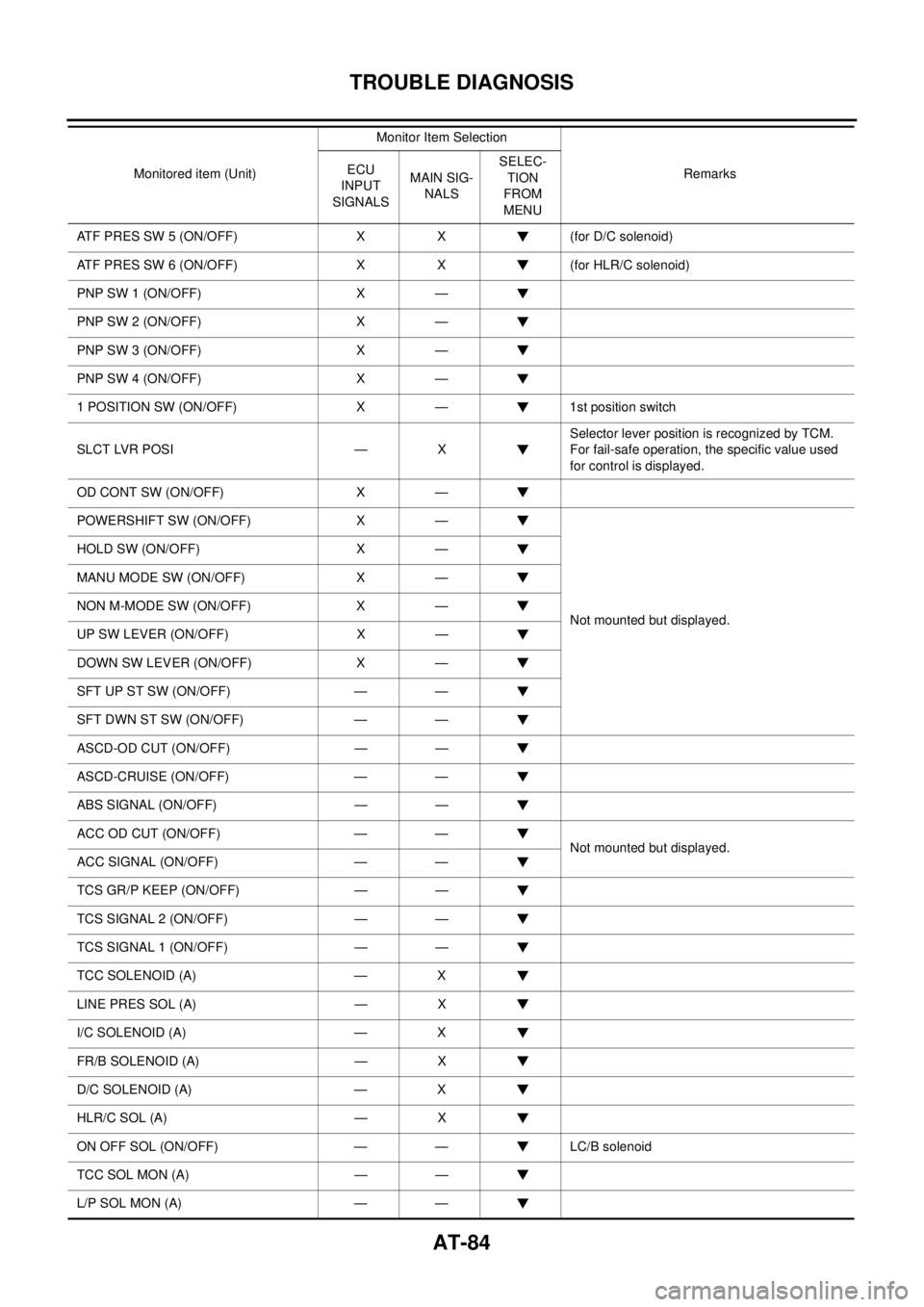
ATF PRES SW 5 (ON/OFF) X X (for D/C solenoid)
ATF PRES SW 6 (ON/OFF) X X (for HLR/C solenoid)
PNP SW 1 (ON/OFF) X —
PNP SW 2 (ON/OFF) X —
PNP SW 3 (ON/OFF) X —
PNP SW 4 (ON/OFF) X —
1 POSITION SW (ON/OFF) X — 1st position switch
SLCT LVR POSI — XSelector lever position is recognized by TCM.
For fail-safe operation, the specific value used
for control is displayed.
OD CONT SW (ON/OFF) X —
POWERSHIFT SW (ON/OFF) X —
Not mounted but displayed. HOLD SW (ON/OFF) X —
MANU MODE SW (ON/OFF) X —
NON M-MODE SW (ON/OFF) X —
UP SW LEVER (ON/OFF) X —
DOWN SW LEVER (ON/OFF) X —
SFTUPSTSW(ON/OFF) — —
SFT DWN ST SW (ON/OFF) — —
ASCD-OD CUT (ON/OFF) — —
ASCD-CRUISE (ON/OFF) — —
ABS SIGNAL (ON/OFF) — —
ACC OD CUT (ON/OFF) — —
Not mounted but displayed.
ACC SIGNAL (ON/OFF) — —
TCS GR/P KEEP (ON/OFF) — —
TCS SIGNAL 2 (ON/OFF) — —
TCS SIGNAL 1 (ON/OFF) — —
TCC SOLENOID (A) — X
LINE PRES SOL (A) — X
I/C SOLENOID (A) — X
FR/B SOLENOID (A) — X
D/C SOLENOID (A) — X
HLR/C SOL (A) — X
ON OFF SOL (ON/OFF) — — LC/B solenoid
TCC SOL MON (A) — —
L/P SOL MON (A) — —Monitored item (Unit)Monitor Item Selection
Remarks ECU
INPUT
SIGNALSMAIN SIG-
NALSSELEC-
TION
FROM
MENU
Page 225 of 3171

KEY INTERLOCK CABLE
AT-217
D
E
F
G
H
I
J
K
L
MA
B
AT
REMOVAL
1. Remove center console. Refer toIP-16, "CENTER CONSOLE".
2. Remove lower instrument panel LH (for LHD models) or lower instrument panel RH (for RHD models) and
cluster lid A. Refer toIP-13, "
LOWER INSTRUMENT PANEL LH",IP-15, "LOWER INSTRUMENT
PANEL RH AND GLOVE BOX",IP-10, "INSTRUMENT PANEL".
3. Unlock slider by squeezing lock tabs on slider from adjuster
holder.
4. Remove casing cap from bracket of control device assembly
and remove interlock rod from adjuster holder.
5. Remove holder from key cylinder and remove key interlock
cable.
INSTALLATION
1. Set key interlock cable to key cylinder and install holder.
2. Turn ignition key to lock position.
3. Set selector lever to “P” position.
4. Insert interlock rod into adjuster holder.
5. Install casing cap to bracket.
6. Move slider in order to secure adjuster holder to interlock rod.
CAUTION:
Do not touch any other areas than slider or apply any force
to slider except in the sliding direction.
7. Install lower instrument panel LH (for LHD models) or lower
instrument panel RH (for RHD models) and cluster lid A. Refer
toIP-13, "
LOWER INSTRUMENT PANEL LH",IP-15, "LOWER
INSTRUMENT PANEL RH AND GLOVE BOX",IP-10,
"INSTRUMENT PANEL".
8. Install center console. Refer toIP-16, "
CENTER CONSOLE".
SCIA6793E
SCIA6900E
SCIA6900E
SCIA1232E
Page 338 of 3171

ATC-4
PRECAUTIONS
PRECAUTIONS
PFP:00001
Precautions for Supplemental Restraint System (SRS) “AIR BAG” and “SEAT
BELT PRE-TENSIONER”
EJS006AK
The Supplemental Restraint System such as “AIR BAG” and “SEAT BELT PRE-TENSIONER”, used along
with a front seat belt, helps to reduce the risk or severity of injury to the driver and front passenger for certain
types of collision. Information necessary to service the system safely is included in the SRS and SB section of
this Service Manual.
WARNING:
lTo avoid rendering the SRS inoperative, which could increase the risk of personal injury or death
in the event of a collision which would result in air bag inflation, all maintenance must be per-
formed by an authorized NISSAN/INFINITI dealer.
lImproper maintenance, including incorrect removal and installation of the SRS, can lead to per-
sonal injury caused by unintentional activation of the system. For removal of Spiral Cable and Air
Bag Module, see the SRS section.
lDo not use electrical test equipment on any circuit related to the SRS unless instructed to in this
Service Manual. SRS wiring harnesses can be identified by yellow and/or orange harnesses or
harness connectors.
Precautions for Working with HFC-134a (R-134a)EJS006AL
WARNING:
lCFC-12 (R-12) refrigerant and HFC-134a (R-134a) refrigerant are not compatible. These refrigerants
must never be mixed, even in the smallest amounts. If the refrigerants are mixed and compressor
malfunction is likely occur.
lUse only specified lubricant for the HFC-134a (R-134a) A/C system and HFC-134a (R-134a) compo-
nents. If lubricant other than that specified is used, compressor malfunction is likely to occur.
lThe specified HFC-134a (R-134a) lubricant rapidly absorbs moisture from the atmosphere. The fol-
lowing handling precautions must be observed:
–When removing refrigerant components from a vehicle, immediately cap (seal) the component to
minimize the entry of moisture from the atmosphere.
–When installing refrigerant components to a vehicle, do not remove the caps (unseal) until just
before connecting the components. Connect all refrigerant loop components as quickly as possi-
ble to minimize the entry of moisture into system.
–Only use the specified lubricant from a sealed container. Immediately reseal containers of lubri-
cant. Without proper sealing, lubricant will become moisture saturated and should not be used.
–Avoid breathing A/C refrigerant and lubricant vapor or mist. Exposure may irritate eyes, nose and
throat. Use only approved recovery/recycling equipment to discharge HFC-134a (R-134a) refriger-
ant. If accidental system discharge occurs, ventilate work area before resuming service. Addi-
tional health and safety information may be obtained from refrigerant and lubricant
manufacturers.
–Do not allow lubricant (Nissan A/C System Oil Type S) to come in contact with styrofoam parts.
Damage may result.
Contaminated RefrigerantEJS006AM
If a refrigerant other than pure HFC-134a (R-134a) is identified in a vehicle, your options are:
lExplain to the customer that environmental regulations prohibit the release of contaminated refrigerant
into the atmosphere.
lExplain that recovery of the contaminated refrigerant could damage your service equipment and refriger-
ant supply.
lSuggest the customer return the vehicle to the location of previous service where the contamination may
have occurred.
lIf you choose to perform the repair, recover the refrigerant using onlydedicated equipment and contain-
ers. Do not recover contaminated refrigerant into your existing service equipment.If your facility
does not have dedicated recovery equipment, you may contact a local refrigerant product retailer for avail-
able service. This refrigerant must be disposed of in accordance with all federal and local regulations. In
addition, replacement of all refrigerant system components on the vehicle is recommended.
Page 457 of 3171
AIR CONDITIONER FILTER
ATC-123
C
D
E
F
G
H
I
K
L
MA
B
AT C
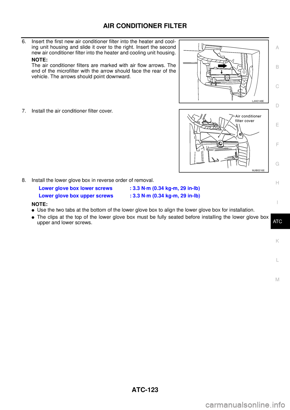
6. Insert the first new air conditioner filter into the heater and cool-
ing unit housing and slide it over to the right. Insert the second
new air conditioner filter into the heater and cooling unit housing.
NOTE:
The air conditioner filters are marked with air flow arrows. The
end of the microfilter with the arrow should face the rear of the
vehicle. The arrows should point downward.
7. Install the air conditioner filter cover.
8. Install the lower glove box in reverse order of removal.
NOTE:
lUse the two tabs at the bottom of the lower glove box to align the lower glove box for installation.
lThe clips at the top of the lower glove box must be fully seated before installing the lower glove box
upper and lower screws.
LJIA0148E
MJIB0216E
Lower glove box lower screws : 3.3 N·m (0.34 kg-m, 29 in-lb)
Lower glove box upper screws : 3.3 N·m (0.34 kg-m, 29 in-lb)
Page 789 of 3171
PRECAUTIONS
BR-3
C
D
E
G
H
I
J
K
L
MA
B
BR
PRECAUTIONSPFP:00001
Precautions for Supplemental Restraint System (SRS) “AIR BAG” and “SEAT
BELT PRE-TENSIONER”
EFS006DL
The Supplemental Restraint System such as “AIR BAG” and “SEAT BELT PRE-TENSIONER”, used along
with a front seat belt, helps to reduce the risk or severity of injury to the driver and front passenger for certain
types of collision. Information necessary to service the system safely is included in the SRS and SB section of
this Service Manual.
WARNING:
lTo avoid rendering the SRS inoperative, which could increase the risk of personal injury or death
in the event of a collision which would result in air bag inflation, all maintenance must be per-
formed by an authorized NISSAN/INFINITI dealer.
lImproper maintenance, including incorrect removal and installation of the SRS, can lead to per-
sonal injury caused by unintentional activation of the system. For removal of Spiral Cable and Air
Bag Module, see the SRS section.
lDo not use electrical test equipment on any circuit related to the SRS unless instructed to in this
Service Manual. SRS wiring harnesses can be identified by yellow and/or orange harnesses or
harness connectors.
Precautions for Brake SystemEFS005SD
lClean dust on front brake and rear brake with a vacuum dust collector. Do not blow with compressed air.
lRecommended fluid is brake fluid “DOT 3” or “DOT 4”.
lNever reuse drained brake fluid.
lBe careful not to splash brake fluid on painted areas; it may cause paint damage. If brake fluid is splashed
on painted areas, wash it away with water immediately.
lTo clean or wash all parts of master cylinder, disc brake caliper, wheel cylinder, use new brake fluid.
lNever use mineral oils such as gasoline or kerosene. They will ruin rubber parts of the hydraulic system.
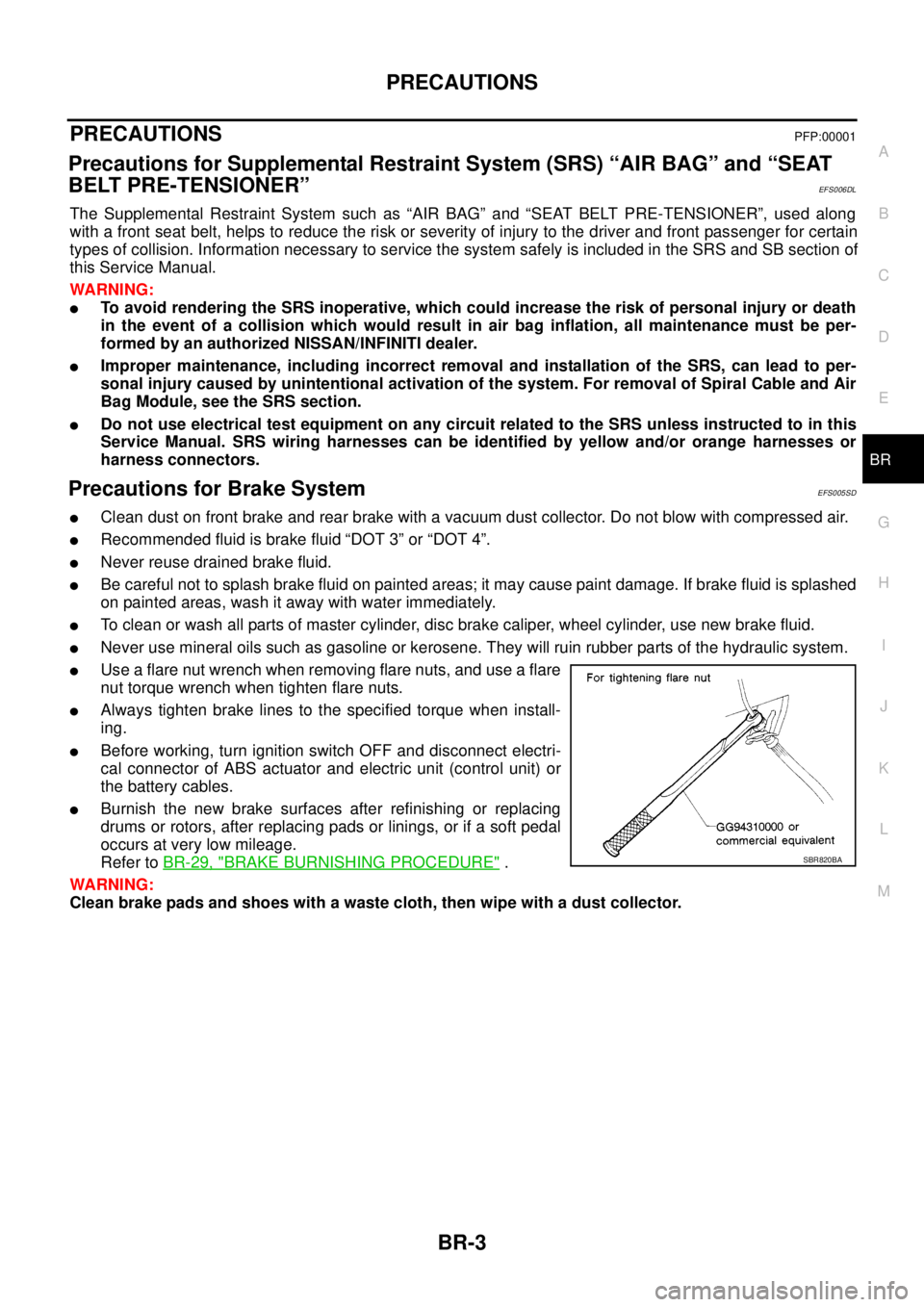
lUse a flare nut wrench when removing flare nuts, and use a flare
nut torque wrench when tighten flare nuts.
lAlways tighten brake lines to the specified torque when install-
ing.
lBefore working, turn ignition switch OFF and disconnect electri-
cal connector of ABS actuator and electric unit (control unit) or
the battery cables.
lBurnish the new brake surfaces after refinishing or replacing
drums or rotors, after replacing pads or linings, or if a soft pedal
occurs at very low mileage.
Refer toBR-29, "
BRAKE BURNISHING PROCEDURE".
WARNING:
Clean brake pads and shoes with a waste cloth, then wipe with a dust collector.SBR820BA
Page 796 of 3171
BR-10
BRAKE FLUID
BRAKE FLUID
PFP:KN100
On-board InspectionEFS005SI
CHECKING BRAKE FLUID LEVEL
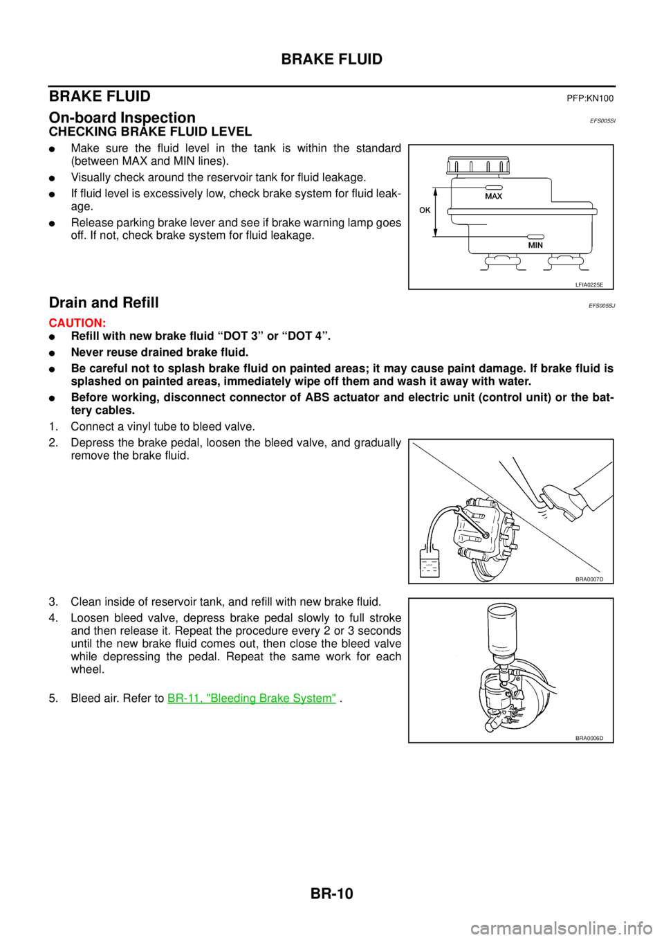
lMake sure the fluid level in the tank is within the standard
(between MAX and MIN lines).
lVisually check around the reservoir tank for fluid leakage.
lIf fluid level is excessively low, check brake system for fluid leak-
age.
lRelease parking brake lever and see if brake warning lamp goes
off. If not, check brake system for fluid leakage.
Drain and RefillEFS005SJ
CAUTION:
lRefill with new brake fluid “DOT 3” or “DOT 4”.
lNever reuse drained brake fluid.
lBe careful not to splash brake fluid on painted areas; it may cause paint damage. If brake fluid is
splashed on painted areas, immediately wipe off them and wash it away with water.
lBefore working, disconnect connector of ABS actuator and electric unit (control unit) or the bat-
tery cables.
1. Connect a vinyl tube to bleed valve.
2. Depress the brake pedal, loosen the bleed valve, and gradually
remove the brake fluid.
3. Clean inside of reservoir tank, and refill with new brake fluid.
4. Loosen bleed valve, depress brake pedal slowly to full stroke
and then release it. Repeat the procedure every 2 or 3 seconds
until the new brake fluid comes out, then close the bleed valve
while depressing the pedal. Repeat the same work for each
wheel.
5. Bleed air. Refer toBR-11, "
Bleeding Brake System".
LFIA0225E
BRA0007D
BRA0006D
Page 797 of 3171
BRAKE FLUID
BR-11
C
D
E
G
H
I
J
K
L
MA
B
BR
Bleeding Brake SystemEFS005SK
CAUTION:
lWhile bleeding, pay attention to master cylinder fluid level.
lBefore working, disconnect electrical connector of ABS actuator and electric unit (control unit) or
the battery cable from the negative terminal.
LHD MODEL
1. Connect a vinyl tube to the rear right bleed valve.
2. Fully depress brake pedal 4 to 5 times.
3. With brake pedal depressed, loosen bleed valve to let the air out, and then tighten it immediately.
4. Repeat steps 3, 4 until no more air comes out.
5. Tighten bleed valve to specified torque. Refer toBR-24, "
Components"(front disc brake),BR-30, "Com-
ponents"(rear drum brake).
6. From the steps 1 to 5 above, with master cylinder reservoir tank filled at least half way, bleed air from the
front left, rear left, and front right brake, in that order.
RHD MODEL
1. Connect a vinyl tube to the rear left bleed valve.
2. Fully depress brake pedal 4 to 5 times.
3. With brake pedal depressed, loosen bleed valve to let the air out, and then tighten it immediately.
4. Repeat steps 3, 4 until no more air comes out.
5. Tighten bleed valve to specified torque. Refer toBR-24, "
Components"(front disc brake),BR-30, "Com-
ponents"(rear drum brake).
6. From the steps 1 to 5 above, with master cylinder reservoir tank filled at least half way, bleed air from the
front right, rear right, and front left brake, in that order.
Page 798 of 3171
BR-12
BRAKE TUBE AND HOSE
BRAKE TUBE AND HOSE
PFP:46300
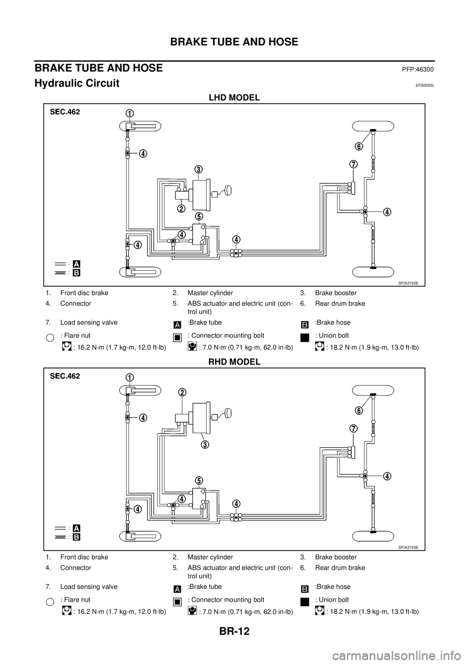
Hydraulic CircuitEFS005SL
LHD MODEL
RHD MODEL
SFIA3192E
1. Front disc brake 2. Master cylinder 3. Brake booster
4. Connector 5. ABS actuator and electric unit (con-
trol unit)6. Rear drum brake
7. Load sensing valve :Brake tube :Brake hose
: Flare nut
: 16.2 N·m (1.7 kg-m, 12.0 ft-lb): Connector mounting bolt
: 7.0 N·m (0.71 kg-m, 62.0 in-lb): Union bolt
: 18.2 N·m (1.9 kg-m, 13.0 ft-lb)
SFIA3193E
1. Front disc brake 2. Master cylinder 3. Brake booster
4. Connector 5. ABS actuator and electric unit (con-
trol unit)6. Rear drum brake
7. Load sensing valve :Brake tube :Brake hose
: Flare nut
: 16.2 N·m (1.7 kg-m, 12.0 ft-lb): Connector mounting bolt
: 7.0 N·m (0.71 kg-m, 62.0 in-lb): Union bolt
: 18.2 N·m (1.9 kg-m, 13.0 ft-lb)