Page 1469 of 3171
PRIMARY TIMING CHAIN
EM-87
C
D
E
F
G
H
I
J
K
L
MA
EM
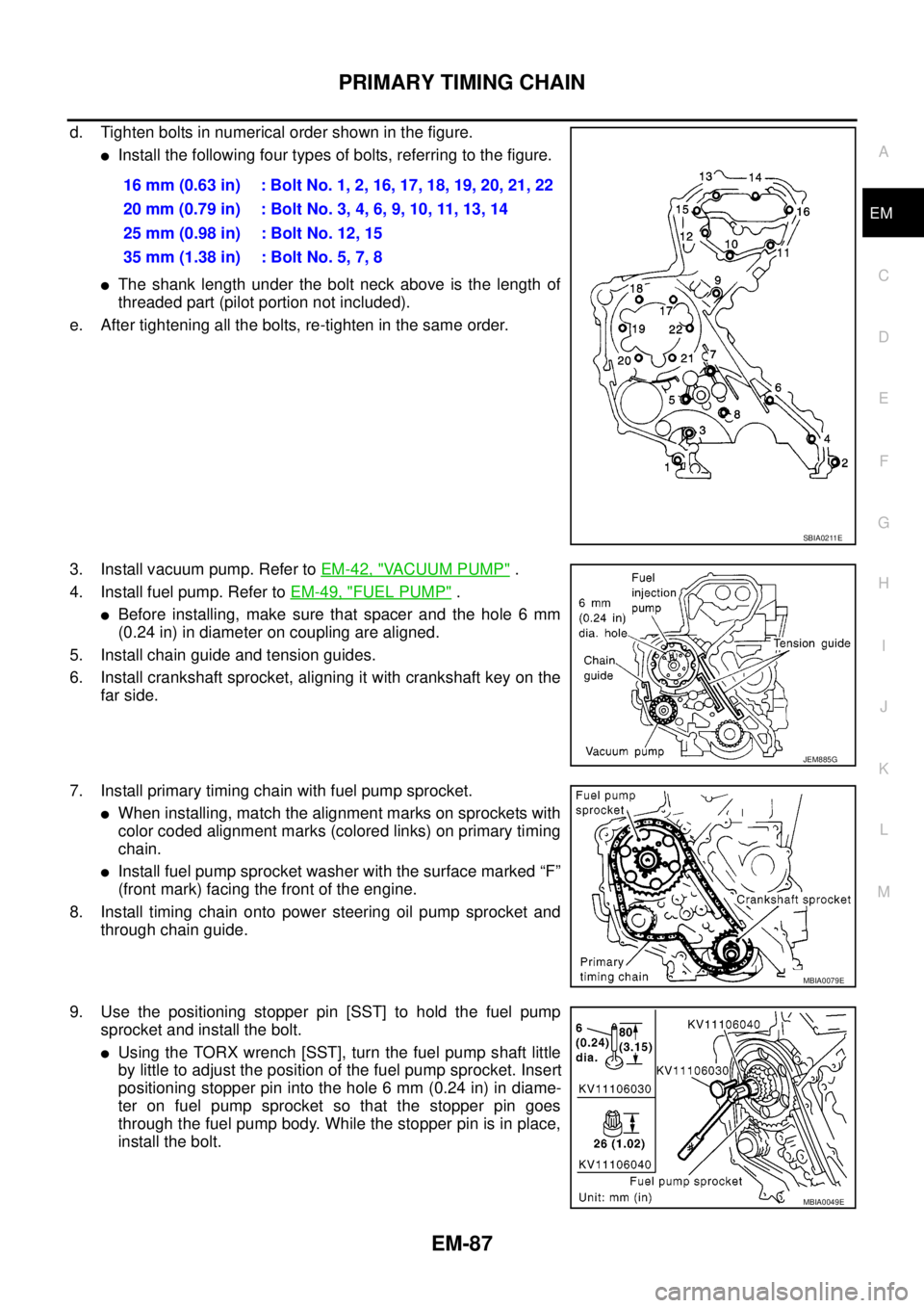
d. Tighten bolts in numerical order shown in the figure.
lInstall the following four types of bolts, referring to the figure.
lThe shank length under the bolt neck above is the length of
threaded part (pilot portion not included).
e. After tightening all the bolts, re-tighten in the same order.
3. Install vacuum pump. Refer toEM-42, "
VACUUM PUMP".
4. Install fuel pump. Refer toEM-49, "
FUEL PUMP".
lBefore installing, make sure that spacer and the hole 6 mm
(0.24 in) in diameter on coupling are aligned.
5. Install chain guide and tension guides.
6. Install crankshaft sprocket, aligning it with crankshaft key on the
far side.
7. Install primary timing chain with fuel pump sprocket.
lWhen installing, match the alignment marks on sprockets with
color coded alignment marks (colored links) on primary timing
chain.
lInstall fuel pump sprocket washer with the surface marked “F”
(front mark) facing the front of the engine.
8. Install timing chain onto power steering oil pump sprocket and
through chain guide.
9. Use the positioning stopper pin [SST] to hold the fuel pump
sprocket and install the bolt.
lUsing the TORX wrench [SST], turn the fuel pump shaft little
by little to adjust the position of the fuel pump sprocket. Insert
positioning stopper pin into the hole 6 mm (0.24 in) in diame-
ter on fuel pump sprocket so that the stopper pin goes
through the fuel pump body. While the stopper pin is in place,
install the bolt.16 mm (0.63 in) : Bolt No. 1, 2, 16, 17, 18, 19, 20, 21, 22
20mm(0.79in) :BoltNo.3,4,6,9,10,11,13,14
25 mm (0.98 in) : Bolt No. 12, 15
35 mm (1.38 in) : Bolt No. 5, 7, 8
SBIA0211E
JEM885G
MBIA0079E
MBIA0049E
Page 1470 of 3171
EM-88
PRIMARY TIMING CHAIN
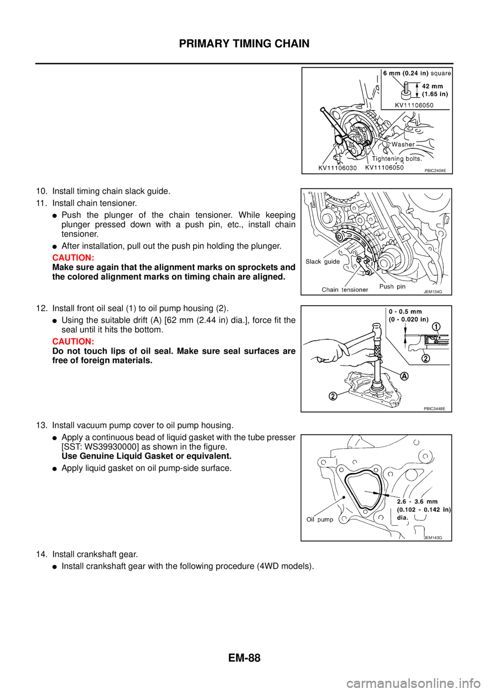
10. Install timing chain slack guide.
11. Install chain tensioner.
lPush the plunger of the chain tensioner. While keeping
plunger pressed down with a push pin, etc., install chain
tensioner.
lAfter installation, pull out the push pin holding the plunger.
CAUTION:
Make sure again that the alignment marks on sprockets and
the colored alignment marks on timing chain are aligned.
12. Install front oil seal (1) to oil pump housing (2).
lUsing the suitable drift (A) [62 mm (2.44 in) dia.], force fit the
seal until it hits the bottom.
CAUTION:
Do not touch lips of oil seal. Make sure seal surfaces are
free of foreign materials.
13. Install vacuum pump cover to oil pump housing.
lApply a continuous bead of liquid gasket with the tube presser
[SST: WS39930000] as shown in the figure.
Use Genuine Liquid Gasket or equivalent.
lApply liquid gasket on oil pump-side surface.
14. Install crankshaft gear.
lInstall crankshaft gear with the following procedure (4WD models).
PBIC2404E
JEM134G
PBIC3448E
JEM143G
Page 1471 of 3171
PRIMARY TIMING CHAIN
EM-89
C
D
E
F
G
H
I
J
K
L
MA
EM
–Align crankshaft gear (1) mating mark and idler sub gear (3)
mating mark (C).
–Remove internal mechanism securing bolt and plate (Service
part: 13012 EB30A and 13013 EB30A) (A).
–If new balancer unit (2) is used, align matching marks (B) of
each gear as shown in the figure.
–Remove securing-bolt-and-plate (A) and securing pin (C) after
installing crankshaft gear (1).
15. Install oil pump housing.
a. Apply a continuous bead of liquid gasket with the tube presser
[SST: WS39930000] as shown in the figure.
A: Leave the start and end areas of the bead slightly protruding
from the surface.
B: Apply liquid gasket along upper end surface of oil pump hous-
ing.
2 : Idler main gear
4 : Balancer drive shaft front end
5 : Idler gear mounting bolt (do not loosen)
B : Snap ring plier
PBIC3471E
PBIC3475E
JEM144G
Page 1472 of 3171
EM-90
PRIMARY TIMING CHAIN
b. Install O-ring into the groove of rear chain case.
c. Install oil pump housing.
lWhen installing, align the inner rotor in the direction of the two facing flats of oil pump drive spacer.
lWhen installing, align the dowel pin with the pin hole.
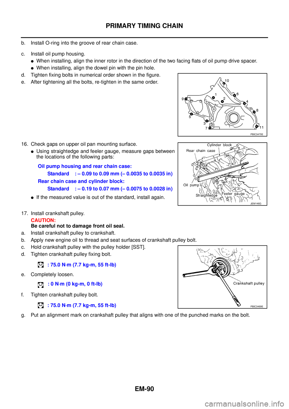
d. Tighten fixing bolts in numerical order shown in the figure.
e. After tightening all the bolts, re-tighten in the same order.
16. Check gaps on upper oil pan mounting surface.
lUsing straightedge and feeler gauge, measure gaps between
the locations of the following parts:
lIf the measured value is out of the standard, install again.
17. Install crankshaft pulley.
CAUTION:
Be careful not to damage front oil seal.
a. Install crankshaft pulley to crankshaft.
b. Apply new engine oil to thread and seat surfaces of crankshaft pulley bolt.
c. Hold crankshaft pulley with the pulley holder [SST].
d. Tighten crankshaft pulley fixing bolt.
e. Completely loosen.
f. Tighten crankshaft pulley bolt.
g. Put an alignment mark on crankshaft pulley that aligns with one of the punched marks on the bolt.
PBIC3470E
Oil pump housing and rear chain case:
Standard : – 0.09 to 0.09 mm (– 0.0035 to 0.0035 in)
Rear chain case and cylinder block:
Standard : – 0.19 to 0.07 mm (– 0.0075 to 0.0028 in)
JEM146G
: 75.0 N·m (7.7 kg-m, 55 ft-lb)
:0N·m(0kg-m,0ft-lb)
: 75.0 N·m (7.7 kg-m, 55 ft-lb)
PBIC3469E
Page 1476 of 3171
EM-94
CYLINDER HEAD
lRefer toGI-10, "Components"for symbol marks in the figure.
Removal and InstallationEBS01E6B
REMOVAL
1. Drain engine coolant. Refer toCO-7, "Changing Engine Coolant".
2. Remove the following:
lRocker cover (Refer toEM-56, "ROCKER COVER".)
lSpill tube and fuel injector (Refer toEM-44, "INJECTION TUBE AND FUEL INJECTOR".)
lIntake manifold (Refer toEM-20, "INTAKE MANIFOLD".)
lTurbocharger (Refer toEM-28, "TURBO CHARGER".)
lExhaust manifold (Refer toEM-34, "EXHAUST MANIFOLD".)
lSecondary timing chain (Refer toEM-73, "SECONDARY TIMING CHAIN".)
lCamshaft (Refer toEM-59, "CAMSHAFT".)
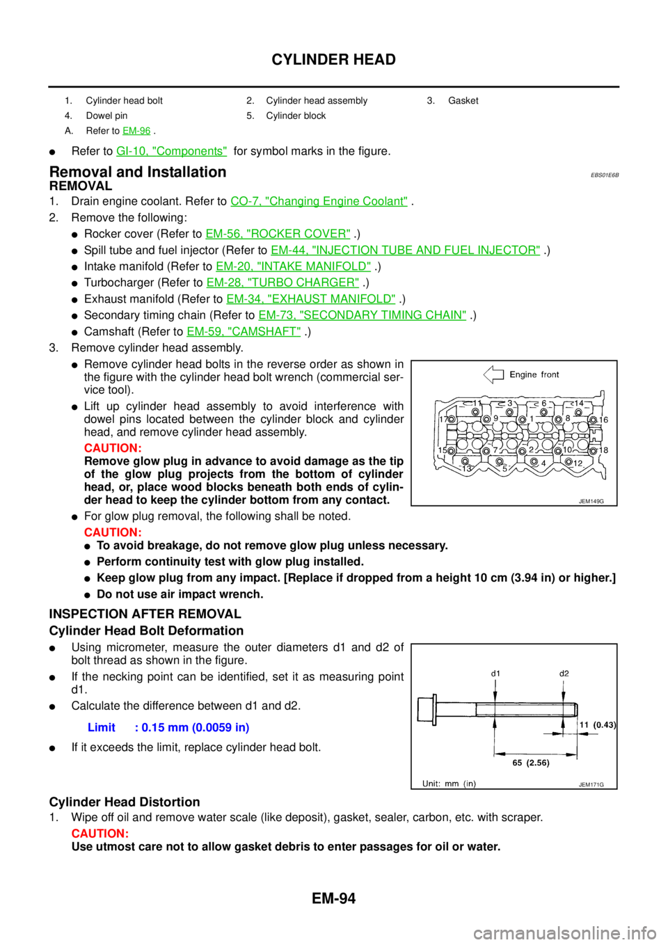
3. Remove cylinder head assembly.
lRemove cylinder head bolts in the reverse order as shown in
the figure with the cylinder head bolt wrench (commercial ser-
vice tool).
lLift up cylinder head assembly to avoid interference with
dowel pins located between the cylinder block and cylinder
head, and remove cylinder head assembly.
CAUTION:
Remove glow plug in advance to avoid damage as the tip
of the glow plug projects from the bottom of cylinder
head, or, place wood blocks beneath both ends of cylin-
der head to keep the cylinder bottom from any contact.
lFor glow plug removal, the following shall be noted.
CAUTION:
lTo avoid breakage, do not remove glow plug unless necessary.
lPerform continuity test with glow plug installed.
lKeep glow plug from any impact. [Replace if dropped from a height 10 cm (3.94 in) or higher.]
lDo not use air impact wrench.
INSPECTION AFTER REMOVAL
Cylinder Head Bolt Deformation
lUsing micrometer, measure the outer diameters d1 and d2 of
bolt thread as shown in the figure.
lIf the necking point can be identified, set it as measuring point
d1.
lCalculate the difference between d1 and d2.
lIf it exceeds the limit, replace cylinder head bolt.
Cylinder Head Distortion
1. Wipe off oil and remove water scale (like deposit), gasket, sealer, carbon, etc. with scraper.
CAUTION:
Use utmost care not to allow gasket debris to enter passages for oil or water.
1. Cylinder head bolt 2. Cylinder head assembly 3. Gasket
4. Dowel pin 5. Cylinder block
A. Refer toEM-96
.
JEM149G
Limit : 0.15 mm (0.0059 in)
JEM171G
Page 2271 of 3171
LU-14
OIL PUMP
OIL PUMP
PFP:15010
Removal and InstallationEBS01E5D
REMOVAL
Remove oil pump housing. Refer toEM-79, "PRIMARY TIMING CHAIN".
INSTALLATION
Note the following, and install in the reverse order of removal.
lWhen installing, align crankshaft flat faces with inner rotor flat faces.
INSPECTION AFTER INSTALLATION
1. Check the engine oil level. Refer toLU-5, "ENGINE OIL".
2. Start engine, and check there is no leaks of engine oil.
3. Stop engine and wait for 10 minutes.
4. Check the engine oil level and add engine oil. Refer toLU-5, "
ENGINE OIL".
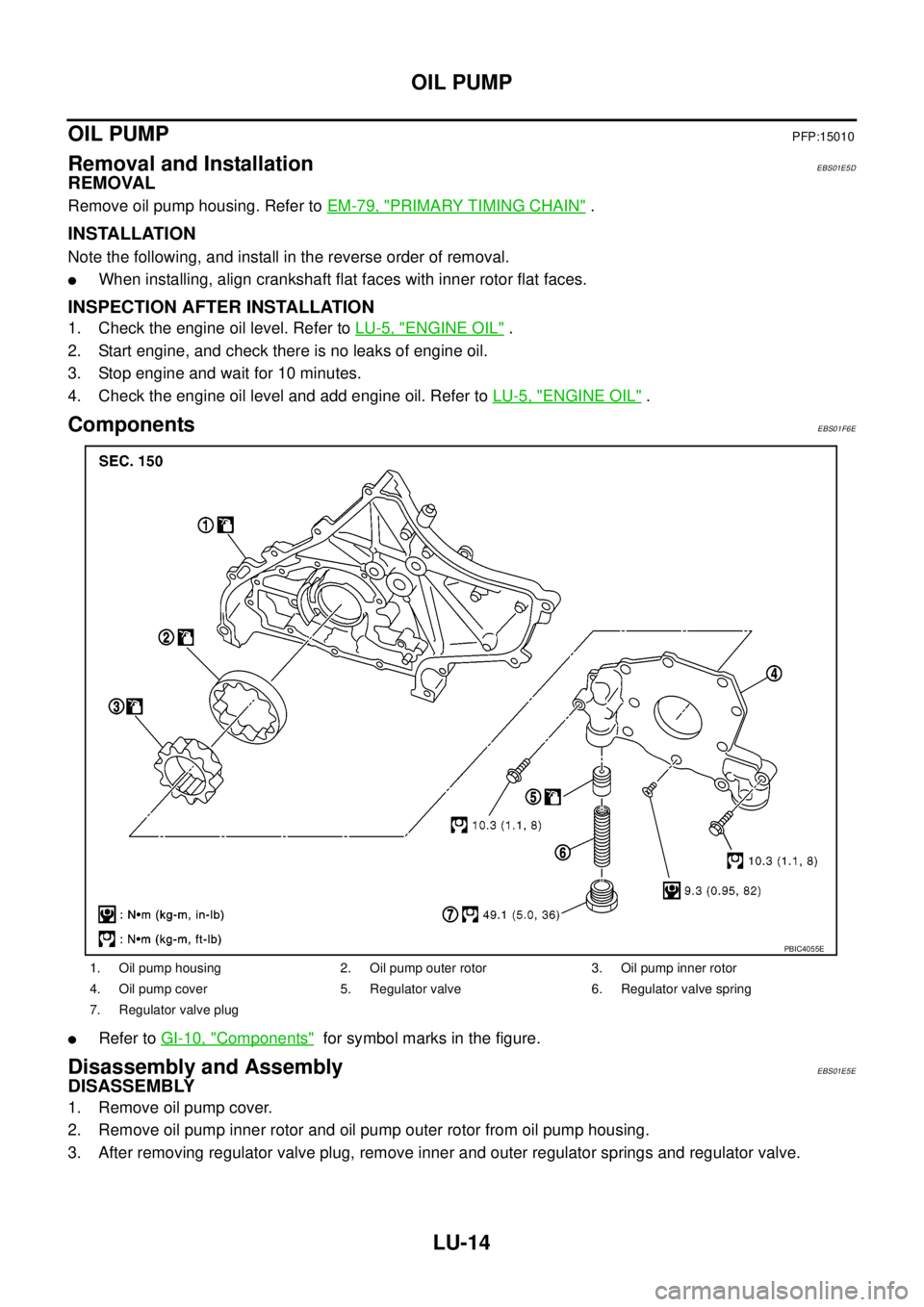
ComponentsEBS01F6E
lRefer toGI-10, "Components"for symbol marks in the figure.
Disassembly and AssemblyEBS01E5E
DISASSEMBLY
1. Remove oil pump cover.
2. Remove oil pump inner rotor and oil pump outer rotor from oil pump housing.
3. After removing regulator valve plug, remove inner and outer regulator springs and regulator valve.
1. Oil pump housing 2. Oil pump outer rotor 3. Oil pump inner rotor
4. Oil pump cover 5. Regulator valve 6. Regulator valve spring
7. Regulator valve plug
PBIC4055E