2005 NISSAN NAVARA horn
[x] Cancel search: hornPage 1 of 3171

MODELD40 SERIES
2005 NISSAN EUROPE S.A.S.
All rights reserved. No part of this Electronic Service Manual may be reproduced or stored in a retrieval system, or transmitted in any
form, or by any means, electronic, mechanical, photocopying, recording or otherwise, without the prior written permission of Nissan
Europe S.A.S., Paris, France.
A GENERAL INFORMATION
B ENGINE
C TRANSMISSION/TRANSAXLE
D DRIVELINE/AXLE
E SUSPENSION F BRAKES
G STEERING H RESTRAINTS
I BODY
J AIR CONDITIONER
K ELECTRICAL
L MAINTENANCE
M INDEXGI General Information
EM Engine Mechanical
LU Engine Lubrication System
CO Engine Cooling System
EC Engine Control System
FL Fuel System
EX Exhaust System
ACC Accelerator Control System
CL Clutch
MTManualTransmission
AT Automatic Transmission
TF Transfer
PR Propeller Shaft
FFD Front Final Drive
RFD Rear Final Drive
FAX Front Axle
RAX Rear Axle
FSU Front Suspension
RSU Rear Suspension
WT Road Wheels & Tires
BR Brake System
PB Parking Brake System
BRC Brake Control System
PS Power Steering System
SB Seat Belts
SRS Supplemental Restraint System (SRS)
BL Body, Lock & Security System
GW Glasses, Window System & Mirrors
RF Roof
EI Exterior & Interior
IP Instrument Panel
SE Seat
ATC Automatic Air Conditioner
MTC Manual Air Conditioner
SC Starting & Charging System
LT Lighting System
DI Driver Information System
WW Wiper, Washer & Horn
BCS Body Control System
LAN LAN System
AV Audio, Visual & Telephone System
ACS Auto Cruise Control System
PG Power Supply, Ground & Circuit Elements
MA Maintenance
IDX Alphabetical Index
QUICK REFERENCE INDEX
A
B
C
D
E
F
G
H
I
J
K
L
M
Page 602 of 3171

BL-18
RADIATOR CORE SUPPORT
RADIATOR CORE SUPPORT
PFP:62500
Removal and InstallationEIS00DGJ
REMOVAL
1. Remove the hood assembly. Refer toBL-14, "Removal and Installation of Hood Assembly".
2. Remove the front grille. Refer toEI-19, "
FRONT GRILLE".
3. Remove the front bumper, bumper reinforcement and bumper bracket. Refer toEI-15, "
FRONT BUMPER"
.
4. Remove the headlamp assembly (LH/RH). Refer toLT-30, "
Removal and Installation".
5. Remove the air intake duct (Air guide). Refer toEM-15, "
AIR CLEANER AND AIR DUCT".
6. Remove the charge air cooler. (for YD25 engine models only) Refer toEM-18, "
CHARGE AIR COOLER".
7. Remove the power steering oil cooler. Refer toPS-30, "
HYDRAULIC LINE".
8. Remove the A/T fluid cooler and A/T fluid cooler tube mounting nuts. Refer toAT- 2 4 4 , "
A/T FLUID
COOLER".
9. Remove the hood lock assembly, and then remove the hood lock cable. Refer toBL-15, "
Removal and
Installation of Hood Lock Control".
10. Remove the horn harness connector.
11. Disconnect the ambient sensor connector and remove the ambient sensor. Refer toAT C - 11 7 , "
Removal
and Installation".
12. Remove the mounting harness clip on radiator core support assembly, the harness is separate.
13. Remove the upper radiator bracket. Refer toCO-11, "
RADIATOR".
1. Radiator core support assembly 2. Air intake duct (Air guide) RH 3. Air intake duct (Air guide) LH
4. Horn (Low) 5. Headlamp lower bracket RH 6. Headlamp lower bracket LH
7. Headlamp side bracket RH 8. Headlamp side bracket LH
MIIB0979E
Page 603 of 3171

RADIATOR CORE SUPPORT
BL-19
C
D
E
F
G
H
J
K
L
MA
B
BL
14. Remove the radiator core support mounting bolts and remove the radiator core support assembly.
15. After removing the radiator core support assembly, the following parts are separate.
lHorn (Low).
lHeadlamp side bracket (LH/RH).
lHeadlamp lower bracket (LH/RH).
INSTALLATION
Install in the reverse order of removal.
CAUTION:
After installing, check the hood adjustment and hood opener operation. Refer toBL-12, "
Fitting
Adjustment"andBL-17, "Hood Lock Control Inspection".
Page 675 of 3171

MULTI-REMOTE CONTROL SYSTEM
BL-91
C
D
E
F
G
H
J
K
L
MA
B
BL
System DescriptionEIS00DBE
INPUTS
Power is supplied at all times
lto BCM terminal 57
lthrough 50A fusible link (letterG, located in the fuse and fusible link box).
lto BCM terminal 41
lthrough 10A fuse [No. 21, located in the fuse block (J/B)].
When the key switch is ON (key is inserted in ignition key cylinder), power is supplied
lto BCM terminal 5
lthrough key switch terminals 2 and 1
lthrough 10A fuse [No. 22, located in the fuse block (J/B)].
When the ignition switch is ACC or ON, power is supplied
lto BCM terminal 4
lthrough 10A fuse [No. 4, located in the fuse block (J/B)].
When the ignition switch is ON or START, power is supplied
lto BCM terminal 3
lthrough 10A fuse [No. 1, located in the fuse block (J/B)].
When the front door switch (driver side) is ON (door is OPEN), ground is supplied
lto BCM terminal 15
lthrough front door switch (driver side) terminal 2
lto front door switch (driver side) case ground.
When the front door switch (passenger side) is ON (door is OPEN), ground is supplied
lto BCM terminal 14
lthrough front door switch (passenger side) terminal 2
lto front door switch (passenger side) case ground.
When the rear door switch LH is ON (door is OPEN), ground is supplied
lto BCM terminal 16
lthrough rear door switch LH terminal 2
lto rear door switch LH case ground.
When the rear door switch RH is ON (door is OPEN), ground is supplied
lto BCM terminal 12
lthrough rear door switch RH terminal 2
lto rear door switch RH case ground.
The multi-remote control system controls operation of the
lpowerdoorlock
linterior lamp and ignition keyhole illumination
lhazard reminder
lauto door lock operation
OPERATING PROCEDURE
Power Door Lock Operation
BCM receives a LOCK signal from keyfob. BCM locks all doors with input of LOCK signal from keyfob.
When an UNLOCK signal is sent from keyfob once, driver's door is unlocked.
Then, if an UNLOCK signal is sent from keyfob again within 5 seconds, all doors are unlocked.
Hazard Reminder
When the doors are locked or unlocked by keyfob, power is supplied to hazard warning lamp.
Hazard reminder does not operate if any door switches are ON (any doors are OPEN).
How to change hazard and horn reminder mode
Hazard and horn reminder can be changed using “WORK SUPPORT” mode in “MULTI ANSWER BACK SET”.
Refer toBL-102, "
CONSULT-II Function (BCM)".
Page 688 of 3171

BL-104
MULTI-REMOTE CONTROL SYSTEM
Work Support
HORN CHIRP SET
HAZARD LAMP SET
AUTO LOCK SET
Trouble Diagnosis ProcedureEIS00DBM
1. Check the trouble symptom and customer's requests.
2. Understand outline of system. Refer toBL-91, "
System Description".
3. Confirm the power door lock system operates normally.
Refer toBL-21, "
POWER DOOR LOCK SYSTEM".
4. Refer to trouble diagnosis chart by symptom, repair or replace any malfunctioning parts. Refer toBL-105,
"Trouble Diagnosis Chart by Symptom".
5. Inspection End.
Test Item Description
REMO CONT ID CONFIR It can be checked whether keyfob ID code is registered or not in this mode.
HAZARD LAMP SETHazard lamp function mode can be changed in this mode. The function mode will be changed when
"CHANG SETT" on CONSULT-II screen is touched.
HAZARD LAMP SETHazard reminder mode can be changed in this mode. The hazard reminder mode will be changed
when “CHANGE SETT” on CONSULT-II screen is touched.
AUTO LOCK SETAuto locking function mode can be changed in this mode. The function mode will be changed when
"CHANG SETT" on CONSULT-II screen is touched.
Horn chirp function ON OFF
MODE1 MODE2 MODE3 MODE4
Hazard lamp operation mode Nothing Unlock only Lock only Lock and Unlock
MODE 1 MODE 2 MODE 3
Auto locking function 1 minutes Nothing 5 minutes
Page 689 of 3171

MULTI-REMOTE CONTROL SYSTEM
BL-105
C
D
E
F
G
H
J
K
L
MA
B
BL
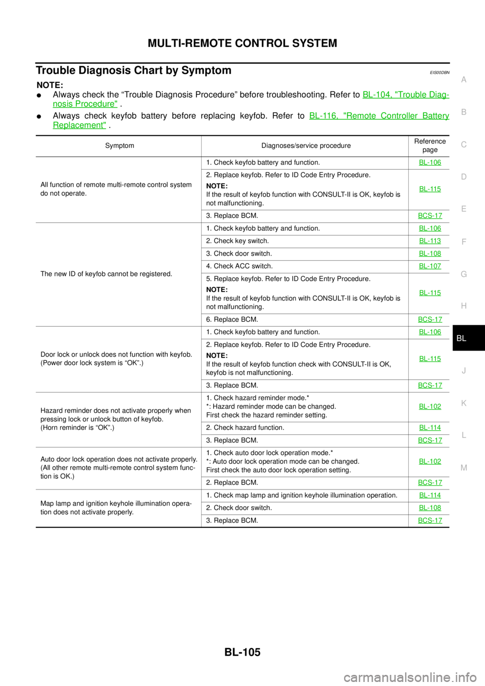
Trouble Diagnosis Chart by SymptomEIS00DBN
NOTE:
lAlways check the “Trouble Diagnosis Procedure” before troubleshooting. Refer toBL-104, "Trouble Diag-
nosis Procedure".
lAlways check keyfob battery before replacing keyfob. Refer toBL-116, "Remote Controller Battery
Replacement".
Symptom Diagnoses/service procedureReference
page
All function of remote multi-remote control system
do not operate.1. Check keyfob battery and function.BL-106
2. Replace keyfob. Refer to ID Code Entry Procedure.
NOTE:
If the result of keyfob function with CONSULT-II is OK, keyfob is
not malfunctioning.BL-115
3. Replace BCM.BCS-17
The new ID of keyfob cannot be registered.1. Check keyfob battery and function.BL-106
2. Check key switch.BL-113
3. Check door switch.BL-108
4. Check ACC switch.BL-107
5. Replace keyfob. Refer to ID Code Entry Procedure.
NOTE:
If the result of keyfob function with CONSULT-II is OK, keyfob is
not malfunctioning.BL-115
6. Replace BCM.BCS-17
Door lock or unlock does not function with keyfob.
(Power door lock system is “OK”.)1. Check keyfob battery and function.BL-106
2. Replace keyfob. Refer to ID Code Entry Procedure.
NOTE:
If the result of keyfob function check with CONSULT-II is OK,
keyfob is not malfunctioning.BL-115
3. Replace BCM.BCS-17
Hazard reminder does not activate properly when
pressing lock or unlock button of keyfob.
(Horn reminder is “OK”.)1. Check hazard reminder mode.*
*: Hazard reminder mode can be changed.
First check the hazard reminder setting.BL-102
2. Check hazard function.BL-114
3. Replace BCM.BCS-17
Auto door lock operation does not activate properly.
(All other remote multi-remote control system func-
tion is OK.)1. Check auto door lock operation mode.*
*: Auto door lock operation mode can be changed.
First check the auto door lock operation setting.BL-102
2. Replace BCM.BCS-17
Map lamp and ignition keyhole illumination opera-
tion does not activate properly.1. Check map lamp and ignition keyhole illumination operation.BL-1142. Check door switch.BL-108
3. Replace BCM.BCS-17
Page 724 of 3171

BL-140
THEFT WARNING SYSTEM
System Description
EIS00DBX
DESCRIPTION
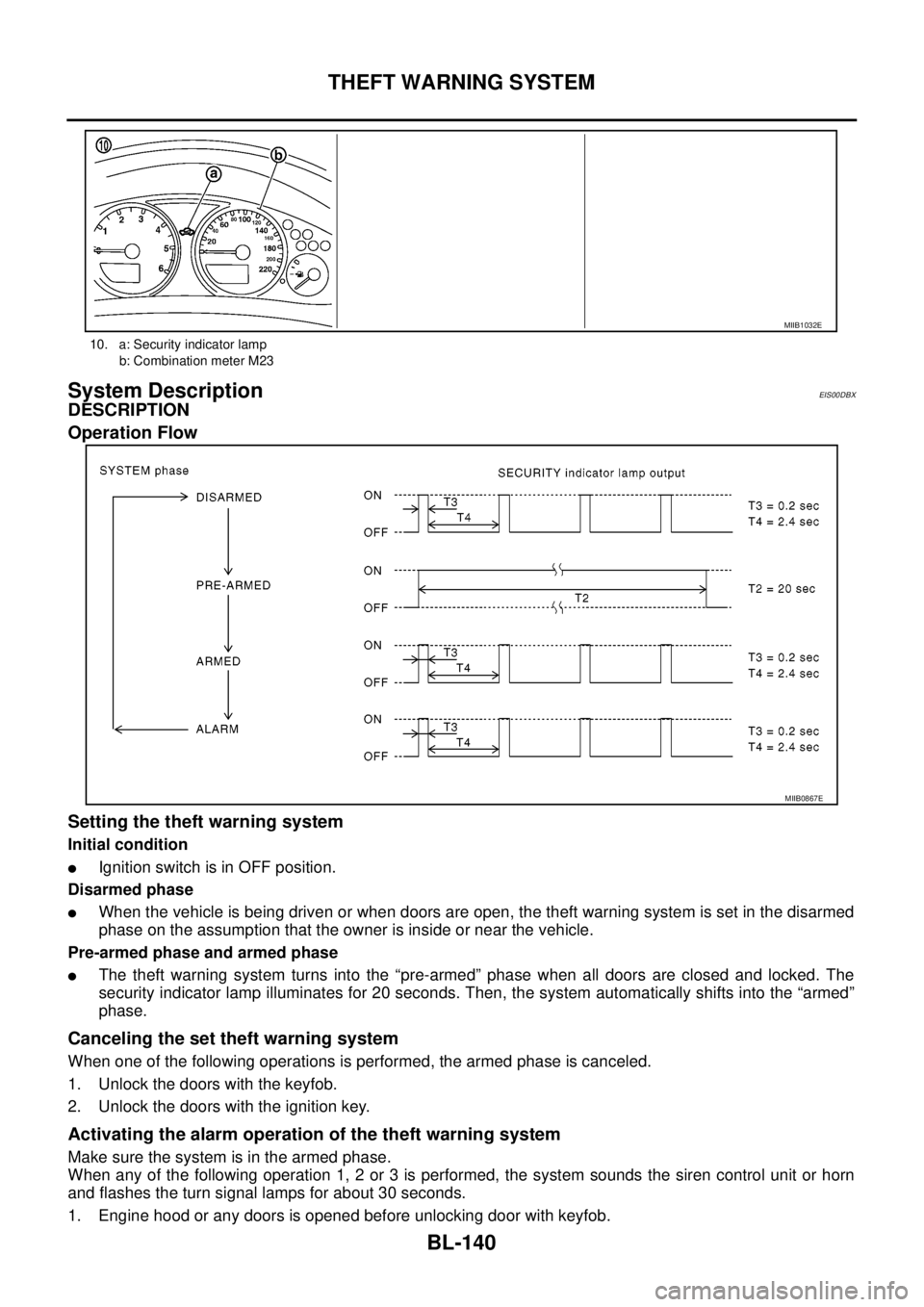
Operation Flow
Setting the theft warning system
Initial condition
lIgnition switch is in OFF position.
Disarmed phase
lWhen the vehicle is being driven or when doors are open, the theft warning system is set in the disarmed
phase on the assumption that the owner is inside or near the vehicle.
Pre-armed phase and armed phase
lThe theft warning system turns into the “pre-armed” phase when all doors are closed and locked. The
security indicator lamp illuminates for 20 seconds. Then, the system automatically shifts into the “armed”
phase.
Canceling the set theft warning system
When one of the following operations is performed, the armed phase is canceled.
1. Unlock the doors with the keyfob.
2. Unlock the doors with the ignition key.
Activating the alarm operation of the theft warning system
Make sure the system is in the armed phase.
When any of the following operation 1, 2 or 3 is performed, the system sounds the siren control unit or horn
and flashes the turn signal lamps for about 30 seconds.
1. Engine hood or any doors is opened before unlocking door with keyfob.
10. a: Security indicator lamp
b: Combination meter M23
MIIB1032E
MIIB0867E
Page 725 of 3171

THEFT WARNING SYSTEM
BL-141
C
D
E
F
G
H
J
K
L
MA
B
BL
2. A door is unlocked without using the keyfob.
3. Disconnect and connecting the battery connector before canceling armed phase.
POWER SUPPLY AND GROUND CIRCUIT
Power is supplied at all times
lthrough 10A fuse [No.19, located in the fuse block (J/B)]
lto combination meter (security indicator lamp) terminal 3
lthrough 50A fusible link (letterG, located in the fuse and fusible link box)
lto BCM terminal 57
lthrough 10A fuse [No. 21, located in the fuse block (J/B)]
lto BCM terminal 41
lthrough 15A fuse (No. 30, located in the fuse and fusible link box)
lto horn relay terminal 2
lthrough 20A fuse (No. 52, located in the IPDM E/R)
lthrough 20A fuse (No. 53, located in the IPDM E/R),
lto IPDM E/R internal CPU.
With the ignition switch in the ACC or ON position, power is supplied
lthrough 10A fuse [No. 4, located in the fuse block (J/B)]
lto BCM terminal 4.
Ground is supplied
lto BCM terminal 55
lthrough body grounds M21, M80 and M83
lto IPDM E/R terminals 38 and 59
lthrough body ground E21, E41 and E61.
INITIAL CONDITION TO ACTIVATE THE SYSTEM
The operation of the theft warning system is controlled by the engine hood and doors.
To activate the theft warning system, BCM must receive signals indicating the doors are closed and locked.
When a door is open, BCM terminal 12, 14, 15 or 16 receives a ground signal from each door switch.
When the engine hood is open, IPDM E/R terminal 41 receives a ground signal
THEFT WARNING SYSTEM ALARM OPERATION
The vehicle security system is triggered by
lopening a door
lopening the hood
ldetecting battery disconnect/connection.
The vehicle security system will be triggered once the system is in armed phase,
when BCM receives a ground signal at terminals 12, 14, 15, 16 (door switch) or IPDM E/R receives a ground
signal at terminal 41 (hood switch).
When the vehicle security system is triggered, siren control unit or horn is activate.
The alarm automatically turns off after 30 seconds, but will reactivate if the vehicle is tampered with again.
THEFT WARNING SYSTEM DEACTIVATION
To deactivate the theft warning system, a door must be unlocked with keyfob.
When the BCM receives either one of these signals or unlock signal from keyfob the theft warning system is
deactivated. (Disarmed phase)
CAN Communication System DescriptionEIS00DBY
Refer toLAN-23, "CAN COMMUNICATION".