2005 NISSAN NAVARA horn
[x] Cancel search: hornPage 740 of 3171

BL-156
THEFT WARNING SYSTEM
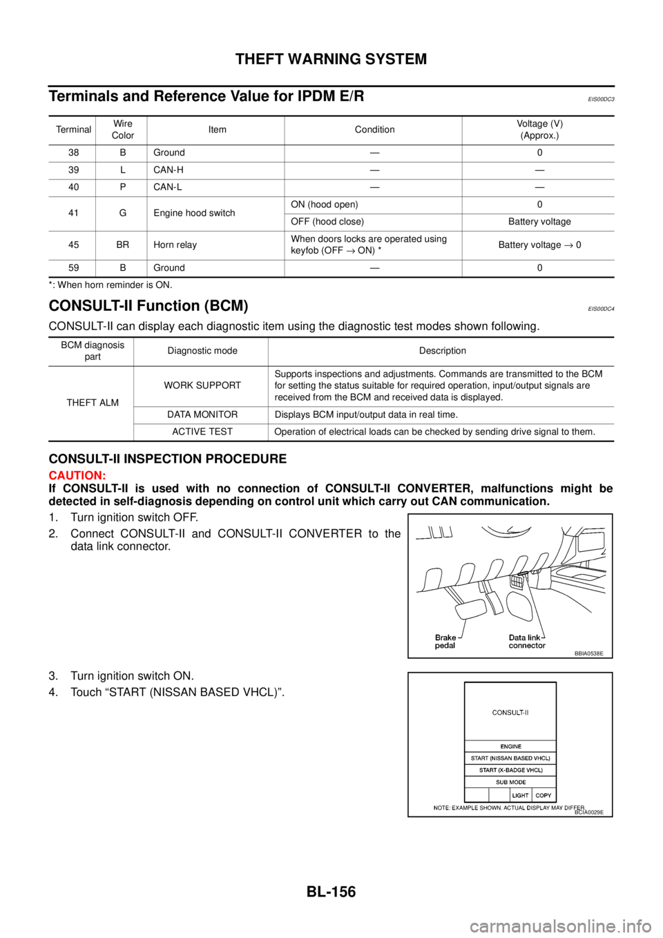
TerminalsandReferenceValueforIPDME/R
EIS00DC3
*: When horn reminder is ON.
CONSULT-II Function (BCM)EIS00DC4
CONSULT-II can display each diagnostic item using the diagnostic test modes shown following.
CONSULT-II INSPECTION PROCEDURE
CAUTION:
If CONSULT-II is used with no connection of CONSULT-II CONVERTER, malfunctions might be
detected in self-diagnosis depending on control unit which carry out CAN communication.
1. Turn ignition switch OFF.
2. Connect CONSULT-II and CONSULT-II CONVERTER to the
data link connector.
3. Turn ignition switch ON.
4. Touch “START (NISSAN BASED VHCL)”.
TerminalWire
ColorItem ConditionVoltage (V)
(Approx.)
38 B Ground — 0
39 L CAN-H — —
40 P CAN-L — —
41 G Engine hood switchON (hood open) 0
OFF (hood close) Battery voltage
45 BR Horn relayWhen doors locks are operated using
keyfob (OFF®ON) *Battery voltage®0
59 B Ground — 0
BCM diagnosis
partDiagnostic mode Description
THEFT ALMWORK SUPPORTSupports inspections and adjustments. Commands are transmitted to the BCM
for setting the status suitable for required operation, input/output signals are
received from the BCM and received data is displayed.
DATA MONITOR Displays BCM input/output data in real time.
ACTIVE TEST Operation of electrical loads can be checked by sending drive signal to them.
BBIA0538E
BCIA0029E
Page 742 of 3171

BL-158
THEFT WARNING SYSTEM
Active Test
Work Support
KEY CYL LK-SW This is displayed even when it is not equipped.
KEY CYL UN-SW This is displayed even when it is not equipped.
CDL LOCK SW Indicates [ON/OFF] condition of lock signal from door lock/unlock switch LH and RH.
CDL UNLOCK SW Indicates [ON/OFF] condition of unlock signal from door lock/unlock switch LH and RH.
AUTO RELOCK This is displayed even when it is not equipped.
GLS BREAK SEN This is displayed even when it is not equipped.Monitored Item Description
Test Item Description
THEFT INDThis test is able to check security indicator lamp operation. The lamp will be turned on when “ON”
on CONSULT-II screen is touched.
FLASHERThis test is able to check theft warning turn signal lamp operation. The turn signal lamp will be
activated on when “ON” on CONSULT-II screen is touched.
VEHICLE SECURITY HORNThis test is able to check theft warning alarm operation. The horns will be activated for 0.5 sec-
onds after “ON” on CONSULT-II screen is touched.
Test Item Description
SECURITY ALARM SET This mode can confirm and change theft warning alarm ON-OFF setting.
THEFT ALM TRGThe switch which triggered theft warning alarm is recorded. This mode is able to confirm and
erase the record of theft warning alarm. The trigger data can be erased by touching “CLEAR” on
CONSULT-II screen.
Page 745 of 3171

THEFT WARNING SYSTEM
BL-161
C
D
E
F
G
H
J
K
L
MA
B
BL
Symptom ChartEIS00DC7
*1: Make sure the system is in the armed phase.PROCEDURE
Diagnostic procedure Reference page
SYMPTOM
1Vehicle secu-
rity system
cannot be set
by ····Door switchDiagnostic Procedure 1 (Door, hood and trunk room lamp switch
check)BL-162
Key fob Check remote keyless entry system function.BL-89
BCM If the above systems are “OK”, replace BCM.BCS-17
Security indicator does not turn “ON”.Diagnostic Procedure 2 (Security indicator lamp check)BL-168If the above systems are “OK”, replace BCM.BCS-17
2*1 Vehicle
security sys-
tem does not
alarm when
····Any door is opened.Diagnostic Procedure 1 (Door, hood and trunk room lamp switch
check)BL-162
If the above systems are “OK”, replace BCM.BCS-17
3Vehicle secu-
rity alarm
does not acti-
vate.Horn alarmDiagnostic Procedure 3 (Vehicle security horn alarm check)BL-169If the above systems are “OK”, replace BCM.BCS-17
Turn signal lamp
alarmDiagnostic Procedure 4 (Turn signal lamp alarm check)BL-169
If the above systems are “OK”, replace BCM.BCS-17
4Vehicle secu-
rity system
cannot be
canceled by
····Key fobCheck remote keyless entry system function.BL-89If the above systems are “OK”, replace BCM.BCS-17
Page 753 of 3171

THEFT WARNING SYSTEM
BL-169
C
D
E
F
G
H
J
K
L
MA
B
BL
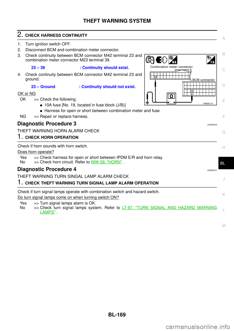
2.CHECK HARNESS CONTINUITY
1. Turn ignition switch OFF.
2. Disconnect BCM and combination meter connector.
3. Check continuity between BCM connector M42 terminal 23 and
combination meter connector M23 terminal 39.
4. Check continuity between BCM connector M42 terminal 23 and
ground.
OK or NG
OK >> Check the following.
l10Afuse[No.19,locatedinfuseblock(J/B)]
lHarness for open or short between combination meter and fuse
NG >> Repair or replace harness.
Diagnostic Procedure 3EIS00DCB
THEFT WARNING HORN ALARM CHECK
1.CHECK HORN OPERATION
Check if horn sounds with horn switch.
Does horn operate?
Yes >> Check harness for open or short between IPDM E/R and horn relay.
No >> Check horn circuit. Refer toWW-59, "
HORN".
Diagnostic Procedure 4EIS00DCC
THEFT WARNING TURN SINGAL LAMP ALARM CHECK
1.CHECK THEFT WARNING TURN SIGNAL LAMP ALARM OPERATION
Check if turn signal lamps operate with combination switch and hazard switch.
DoturnsignallampscomeonwhenturningswitchON?
Yes >> Turn signal lamps alarm is OK.
No >> Check turn signal lamps system. Refer toLT- 9 7 , "
TURN SIGNAL AND HAZARD WARNING
LAMPS". 23 – 39 : Continuity should exist.
23 – Ground : Continuity should not exist.
MIIB0871E
Page 897 of 3171

RADIATOR
CO-13
C
D
E
F
G
H
I
J
K
L
MA
CO
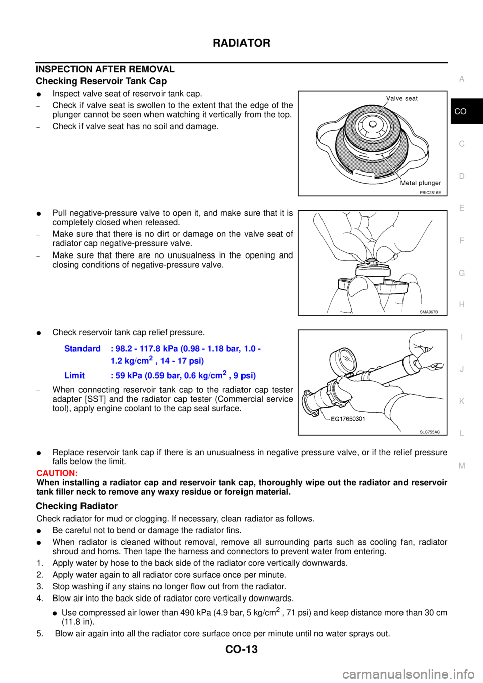
INSPECTION AFTER REMOVAL
Checking Reservoir Tank Cap
lInspect valve seat of reservoir tank cap.
–Check if valve seat is swollen to the extent that the edge of the
plunger cannot be seen when watching it vertically from the top.
–Check if valve seat has no soil and damage.
lPull negative-pressure valve to open it, and make sure that it is
completely closed when released.
–Make sure that there is no dirt or damage on the valve seat of
radiator cap negative-pressure valve.
–Make sure that there are no unusualness in the opening and
closing conditions of negative-pressure valve.
lCheck reservoir tank cap relief pressure.
–When connecting reservoir tank cap to the radiator cap tester
adapter [SST] and the radiator cap tester (Commercial service
tool), apply engine coolant to the cap seal surface.
lReplace reservoir tank cap if there is an unusualness in negative pressure valve, or if the relief pressure
falls below the limit.
CAUTION:
When installing a radiator cap and reservoir tank cap, thoroughly wipe out the radiator and reservoir
tank filler neck to remove any waxy residue or foreign material.
Checking Radiator
Check radiator for mud or clogging. If necessary, clean radiator as follows.
lBe careful not to bend or damage the radiator fins.
lWhen radiator is cleaned without removal, remove all surrounding parts such as cooling fan, radiator
shroud and horns. Then tape the harness and connectors to prevent water from entering.
1. Apply water by hose to the back side of the radiator core vertically downwards.
2. Apply water again to all radiator core surface once per minute.
3. Stop washing if any stains no longer flow out from the radiator.
4. Blow air into the back side of radiator core vertically downwards.
lUse compressed air lower than 490 kPa (4.9 bar, 5 kg/cm2, 71 psi) and keep distance more than 30 cm
(11.8 in).
5. Blow air again into all the radiator core surface once per minute until no water sprays out.
PBIC2816E
SMA967B
Standard : 98.2 - 117.8 kPa (0.98 - 1.18 bar, 1.0 -
1.2 kg/cm
2,14-17psi)
Limit : 59 kPa (0.59 bar, 0.6 kg/cm
2,9psi)
SLC755AC
Page 1756 of 3171

IDX-4
ALPHABETICAL INDEX
Engine control system diagram and chart .........EC-15
Engine coolant ....................................................CO-7
Engine coolant temperature sensor (ECTS) ....EC-103
Engine oil .............................................................LU-5
Engine oil filter replacement .............................MA-26
Engine oil precautions ..........................................GI-7
Engine removal ...............................................EM-106
Engine room cover ............................................EM-20
Engine serial number ..........................................GI-58
Evaporator ....................................ATC-149,MTC-129
Exhaust manifold ..............................................EM-34
Exhaust system ...................................................EX-2
Exhaust system inspection ..................................EX-2
Expansion valve ............................ATC-150,MTC-130
F
F/FOG - Wiring diagram .....................................LT-74
F/PUMP - Wiring diagram ..EC-248,EC-254,EC-260,
EC-266
Final drive pre-inspection .................................FFD-18
Final drive removal and installation ..RFD-14,RFD-81
Flow charts .........................................................GI-24
Fluid temperature sensor (A/T) ........................AT-118
Fluids ................................................................MA-14
Fluorescent leak detector .............ATC-150,MTC-131
Flywheel (clutch) ................................................CL-17
Flywheel runout ..............................................EM-134
Fog lamp, front ....................................................LT-71
Foot lamp ..........................................................LT-145
Fork rod (M/T) ....................................................MT-23
Freeze frame data .............................................EC-28
Front brake solenoid valve .................AT-137,AT-139
Front bumper ......................................................EI-15
Front case (Transfer) ..........................TF-114,TF-120
Front combination lamp removal and installationLT-30
Front door ................BL-118,BL-120,BL-126,GW-35
Front Door Trim ..................................................EI-30
Front drive shaft (Transfer) ...TF-114,TF-120,TF-133
Front final drive removal and installation (4WD) ...........
FFD-15
Front fog lamp .....................................................LT-71
Front passenger air bag ..................................SRS-40
Front seat ...........................................................SE-20
Front seat belt ............................................SB-3,SB-5
Front seat belt pre-tensioner ...............SRS-3,SRS-47
Front side air bag ............................................SRS-43
Front washer ......................................................WW-4
Front wiper .........................................................WW-4
FRPS - Wiring diagram ....................................EC-120
FTS - Wiring diagram .......................................EC-115
Fuel cut control (at no load high engine speed) .EC-20
Fuel filler lid ......................................................BL-136
Fuel filter ............................................................EC-23
Fuel filter replacement ..........................................FL-4
Fuel gauge ............................................................DI-4
Fuel injection control system .............................EC-18
Fuel injector ............EC-25,EC-123,EC-125,EC-237
Fuel injector and fuel tube ................................EM-44
Fuel leak ............................................................EC-88
Fuel line inspection ..............................................FL-3
Fuel pumpEC-86,EC-217,EC-245,EC-251,EC-258,
EC-263
Fuel pump(Learning Value Clearing) .................EC-24
Fuel rail pressure sensor .................................EC-118
Fuel system .........................................................FL-3
Fuel tank ..............................................................FL-9
Fuel temperature sensor ..................................EC-113
Fuse ......................................................PG-74,PG-84
Fuse and fusible link box ..................................PG-84
Fusible link ............................................PG-74,PG-84
G
Garage jack and safety stand .............................GI-52
Gauges .................................................................DI-4
Gear components (M/T) ....................................MT-21
Generator ...........................................................SC-14
Generator - See Alternator ................................SC-14
Glass ........................GW-11,GW-35,GW-38,GW-43
Glove box lamp ................................................LT-162
GLOW - Wiring diagram ..................................EC-296
Glow plug ............................................EM-41,EC-295
Glow relay ........................................................EC-295
Grease ..............................................................MA-14
Ground distribution ...........................................PG-27
H
H/AIM - Wiring diagram .....................................LT-66
Harness connector ............................................PG-75
Harness layout ..................................................PG-38
Hazard warning lamp .........................................LT-97
Headlamp aiming control ...................................LT-66
Headlamp leveler - See Headlamp aiming control ........
LT-66
Headlamp removal and installation ....................LT-30
Heat up switch .................................................EC-319
Heated seat .......................................................SE-12
Heater and cooling unit (Heater core) ..........ATC-124,
ATC-127
,MTC-103,MTC-106
Heater unit (heater core) ..............ATC-124,ATC-127,
MTC-103
,MTC-106
HEATUP - Wiring diagram ...............................EC-320
Height (Dimensions) ...........................................GI-60
HFC134a (R134a) system precaution .ATC-4,MTC-4
HFC134a (R134a) system service procedureATC-138,
MTC-118
HFC134a (R134a) system service tools ........ATC-16,
MTC-16
HFC134a system service equipment precaution ..........
ATC-12
,MTC-12
High and low reverse clutch solenoid valve ....AT-147,
AT-149
HLC - Wiring diagram ......................................WW-41
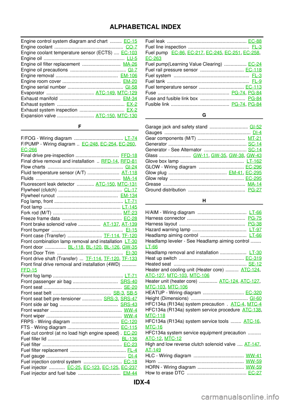
Horn .................................................................WW-59
HORN - Wiring diagram ...................................WW-59
How to erase DTC .............................................EC-27
Page 1810 of 3171
![NISSAN NAVARA 2005 Repair Workshop Manual CAN COMMUNICATION
LAN-33
[CAN]
C
D
E
F
G
H
I
J
L
MA
B
LAN
Input/output signal chart
T: Transmit R: Receive
Signals ECMNAVI con-
trol unitFront air
controlBCMCombina-
tion meterABS actua-
tor and
elect NISSAN NAVARA 2005 Repair Workshop Manual CAN COMMUNICATION
LAN-33
[CAN]
C
D
E
F
G
H
I
J
L
MA
B
LAN
Input/output signal chart
T: Transmit R: Receive
Signals ECMNAVI con-
trol unitFront air
controlBCMCombina-
tion meterABS actua-
tor and
elect](/manual-img/5/57362/w960_57362-1809.png)
CAN COMMUNICATION
LAN-33
[CAN]
C
D
E
F
G
H
I
J
L
MA
B
LAN
Input/output signal chart
T: Transmit R: Receive
Signals ECMNAVI con-
trol unitFront air
controlBCMCombina-
tion meterABS actua-
tor and
electric unit
(control
unit)IPDM E/R
A/C compressor request signal TR
ASCD CRUISE lamp signal T R
ASCD SET lamp signal T R
Cooling fan speed request signal TR
Engine coolant temperature signal T R R
Engine speed signal T R R
Engine status signal T R R
Fuel consumption monitor signalTR
RT
Glow indicator signal T R
Glow relay signal T R
Malfunction indicator signal T R
A/C switch/indicator signal T
R
*
PTC heater signal R T
A/C switch signal R
R
*T
Buzzer output signal T R
Day time running light request signal R T R R
Door switch signal T R R
Front fog light request signal R T R R
Front wiper request signal T R
High beam request signal T R R
Horn chirp signal T R
Low beam request signal T R
Position light request signal T R R
Rear fog light request signal R T R
Rear window defogger switch signal
R
*TR
Sleep wake up signal T R R
Theft warning horn request signal T R
Trailer lamp signal T R
Turn indicator signal T R
Distance to empty signal R T
Fuel level low warning signal R T
ABS warning lamp signalRT
Vehicle speed signalR
*RT
RR
R
*RT
Front wiper stop position signal R T
Hood switch signal R T
Oil pressure switch signalRT
Rear window defogger control signal R T
Page 1812 of 3171
![NISSAN NAVARA 2005 Repair Workshop Manual CAN COMMUNICATION
LAN-35
[CAN]
C
D
E
F
G
H
I
J
L
MA
B
LAN
Closed throttle position signal T R
Cooling fan speed request signal TR
Engine coolant temperature signal T R R
Engine speed signal T R R R
En NISSAN NAVARA 2005 Repair Workshop Manual CAN COMMUNICATION
LAN-35
[CAN]
C
D
E
F
G
H
I
J
L
MA
B
LAN
Closed throttle position signal T R
Cooling fan speed request signal TR
Engine coolant temperature signal T R R
Engine speed signal T R R R
En](/manual-img/5/57362/w960_57362-1811.png)
CAN COMMUNICATION
LAN-35
[CAN]
C
D
E
F
G
H
I
J
L
MA
B
LAN
Closed throttle position signal T R
Cooling fan speed request signal TR
Engine coolant temperature signal T R R
Engine speed signal T R R R
Engine status signal T R R
Fuel consumption monitor signalTR
RT
Glow indicator signal T R
Glow relay signal T R
Malfunction indicator signal T R
Wide open throttle position signal T R
A/T fluid temperature sensor signal T R
A/T position indicator lamp signal T R
OD OFF indicator lamp signal T R
Output shaft revolution signal R T
Turbine revolution signal R T
A/C switch/indicator signal T R
PTC heater signal R T
A/C switch signal R R T
Buzzer output signal T R
Day time running light request signal R T R R
Door switch signalTR R
Front fog light request signal R T R R
Front wiper request signal T R
High beam request signal T R R
Horn chirp signalTR
Low beam request signal T R
Position light request signal T R R
Rear fog light request signal R T R
Rear window defogger switch signal R T R
Sleep wake up signal T R R
Theft warning horn request signal T R
Trailer lamp signalTR
Turn indicator signal T R
1st position switch signal R T
Distance to empty signal R T
Fuel level low warning signal R T
Overdrive control switch signal R T
Stop lamp switch signal R T
ABS operation signal R T
ABS warning lamp signalRT Signals ECM TCMNAVI
control
unitFront air
controlBCMCombi-
nation
meterABS
actuator
and elec-
tric unit
(control
unit)IPDM
E/R