2005 NISSAN NAVARA horn
[x] Cancel search: hornPage 2946 of 3171

DRIVER AIR BAG MODULE
SRS-37
C
D
E
F
G
I
J
K
L
MA
B
SRS
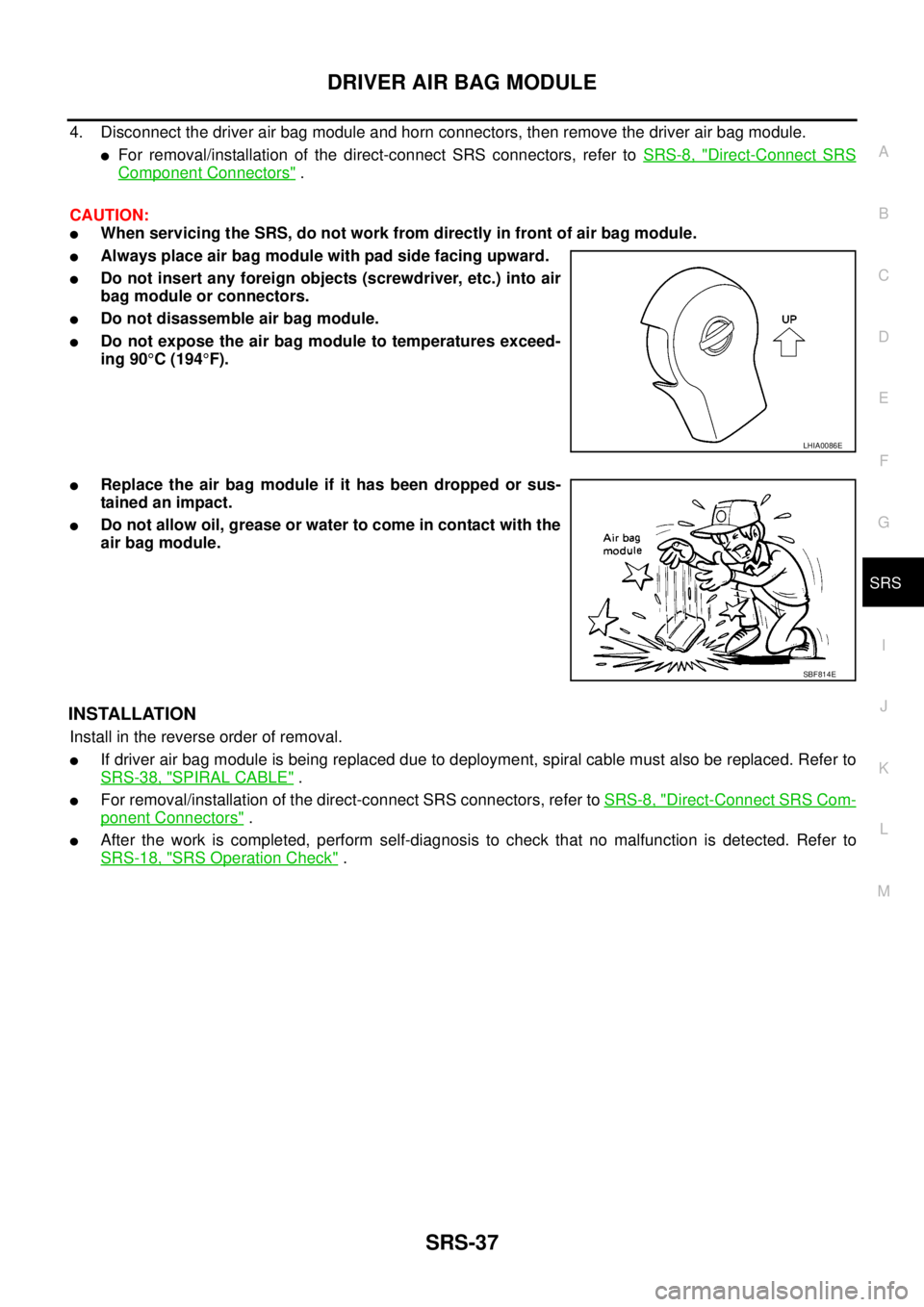
4. Disconnect the driver air bag module and horn connectors, then remove the driver air bag module.
lFor removal/installation of the direct-connect SRS connectors, refer toSRS-8, "Direct-Connect SRS
Component Connectors".
CAUTION:
lWhen servicing the SRS, do not work from directly in front of air bag module.
lAlways place air bag module with pad side facing upward.
lDo not insert any foreign objects (screwdriver, etc.) into air
bag module or connectors.
lDo not disassemble air bag module.
lDo not expose the air bag module to temperatures exceed-
ing 90°C(194°F).
lReplace the air bag module if it has been dropped or sus-
tainedanimpact.
lDo not allow oil, grease or water to come in contact with the
air bag module.
INSTALLATION
Install in the reverse order of removal.
lIf driver air bag module is being replaced due to deployment, spiral cable must also be replaced. Refer to
SRS-38, "
SPIRAL CABLE".
lFor removal/installation of the direct-connect SRS connectors, refer toSRS-8, "Direct-Connect SRS Com-
ponent Connectors".
lAfter the work is completed, perform self-diagnosis to check that no malfunction is detected. Refer to
SRS-18, "
SRS Operation Check".
LHIA0086E
SBF814E
Page 3112 of 3171

WW-1
WIPER, WASHER & HORN
K ELECTRICAL
CONTENTS
C
D
E
F
G
H
I
J
L
M
SECTIONWW
A
B
WW
WIPER, WASHER & HORN
PRECAUTION ............................................................ 3
Precautions for Supplemental Restraint System
(SRS)“AIRBAG”and“SEATBELTPRE-TEN-
SIONER” .................................................................. 3
Wiring Diagrams and Trouble Diagnosis .................. 3
FRONT WIPER AND WASHER SYSTEM .................. 4
Components Parts and Harness Connector Loca-
tion ........................................................................... 4
System Description .................................................. 4
LOW SPEED WIPER OPERATION ...................... 5
HI SPEED WIPER OPERATION ........................... 5
INTERMITTENT OPERATION .............................. 6
AUTO STOP OPERATION .................................... 6
FRONT WASHER OPERATION ........................... 6
MIST OPERATION ................................................ 7
FAIL-SAFE FUNCTION ......................................... 7
COMBINATION SWITCH READING FUNCTION..... 8
CAN Communication System Description .............. 10
Schematic ............................................................... 11
Wiring Diagram — WIPER — ................................ 12
Terminals and Reference Values for BCM ............. 15
Terminals and Reference Values for IPDM E/R ..... 16
How To Proceed With Trouble Diagnosis ............... 16
Preliminary Inspection ............................................ 16
INSPECTION FOR POWER SUPPLY AND
GROUND CIRCUIT ............................................. 16
CONSULT-II Function (BCM) ................................. 18
CONSULT-II OPERATION .................................. 18
WORK SUPPORT ............................................... 19
DATA MONITOR ................................................. 19
ACTIVE TEST ..................................................... 20
CONSULT-II Function (IPDM E/R) ......................... 21
CONSULT-II OPERATION .................................. 21
DATA MONITOR ................................................. 22
ACTIVE TEST ..................................................... 22
Front Wiper Does Not Operate in Rain (Front Wiper
Switch Turned to INT Position) ............................... 23
Front Wiper Does Not Operate .............................. 25
Front Wiper Does Not Return to Stop Position (After
Front Wiper for 10 Seconds, They Stop for 20 sec-onds, and After Repeating the Operations Five
Times, They Become Inoperative) .......................... 28
Only Front Wiper LO Does Not Operate ................. 29
Only Front Wiper HI Does Not Operate .................. 31
Only Front Wiper INT Does Not Operate ................ 32
Front Wiper Intermittent Operation Switch Position
Cannot Be Adjusted ................................................ 33
Front Wiper Interval Time Is Not Controlled by Vehi-
cle Speed ................................................................ 33
Wipers Do Not Wipe When Front Washer Operates... 33
Removal and Installation of Front Wiper Arms,
Adjustment of Wiper Arms Stop Location ............... 34
REMOVAL ........................................................... 34
INSTALLATION ................................................... 34
Removal and Installation of Wiper Motor and Link-
age .......................................................................... 35
REMOVAL ........................................................... 35
INSTALLATION ................................................... 35
Washer Nozzle Adjustment .................................... 36
Washer Tube Layout .............................................. 36
Removal and Installation of Wiper and Washer
Switch ..................................................................... 36
REMOVAL ........................................................... 36
INSTALLATION ................................................... 36
Removal and Installation of Front Washer Tank ..... 37
REMOVAL ........................................................... 37
INSTALLATION ................................................... 37
Removal and Installation of Front Washer Motor ... 38
REMOVAL ........................................................... 38
INSTALLATION ................................................... 38
Removal and Installation of Washer Fluid Level Sen-
sor ........................................................................... 38
REMOVAL ........................................................... 38
INSTALLATION ................................................... 38
HEADLAMP WASHER ............................................. 39
Components Parts and Harness Connector Loca-
tion .......................................................................... 39
System Description ................................................. 39
OUTLINE ............................................................. 40
HEADLAMP WASHER OPERATION .................. 40
Page 3113 of 3171

WW-2
Wiring Diagram — HLC — ..................................... 41
Terminals and Reference Values for BCM .............. 43
Terminals and Reference Values for IPDM E/R ...... 43
How to Proceed with Trouble Diagnosis ................. 44
Preliminary Check .................................................. 44
CHECK POWER SUPPLY AND GROUND CIR-
CUIT .................................................................... 44
CONSULT-II Functions (BCM) ................................ 45
CONSULT-II BASIC OPERATION ....................... 45
DATA MONITOR .................................................. 46
ACTIVE TEST ..................................................... 47
CONSULT-II Functions (IPDM E/R) ........................ 48
CONSULT-II BASIC OPERATION ....................... 48
DATA MONITOR .................................................. 49
ACTIVE TEST ..................................................... 49
Headlamp Washer Does Not Operate .................... 50
Removal and Installation of Washer Nozzle ........... 53
REMOVAL ........................................................... 53
INSTALLATION .................................................... 53
Removal and Installation of Washer Tank .............. 53
Removal and Installation of Headlamp Washer
Motor ...................................................................... 53REMOVAL ............................................................ 53
INSTALLATION .................................................... 53
Washer Tube Layout ............................................... 54
CIGARETTE LIGHTER ............................................. 55
Wiring Diagram — CIGAR — .................................. 55
Removal and Installation of Cigarette Lighter ......... 56
REMOVAL ............................................................ 56
INSTALLATION .................................................... 56
POWER SOCKET ..................................................... 57
Wiring Diagram — P/SCKT — ................................ 57
Removal and Installation of Front Power Socket .... 58
REMOVAL ............................................................ 58
INSTALLATION .................................................... 58
Removal and Installation of Console Power Socket...58
REMOVAL ............................................................ 58
INSTALLATION .................................................... 58
HORN ........................................................................ 59
Wiring Diagram — HORN — .................................. 59
Removal and Installation of Horn ............................ 60
REMOVAL ............................................................ 60
INSTALLATION .................................................... 60
Page 3170 of 3171

HORN
WW-59
C
D
E
F
G
H
I
J
L
MA
B
WW
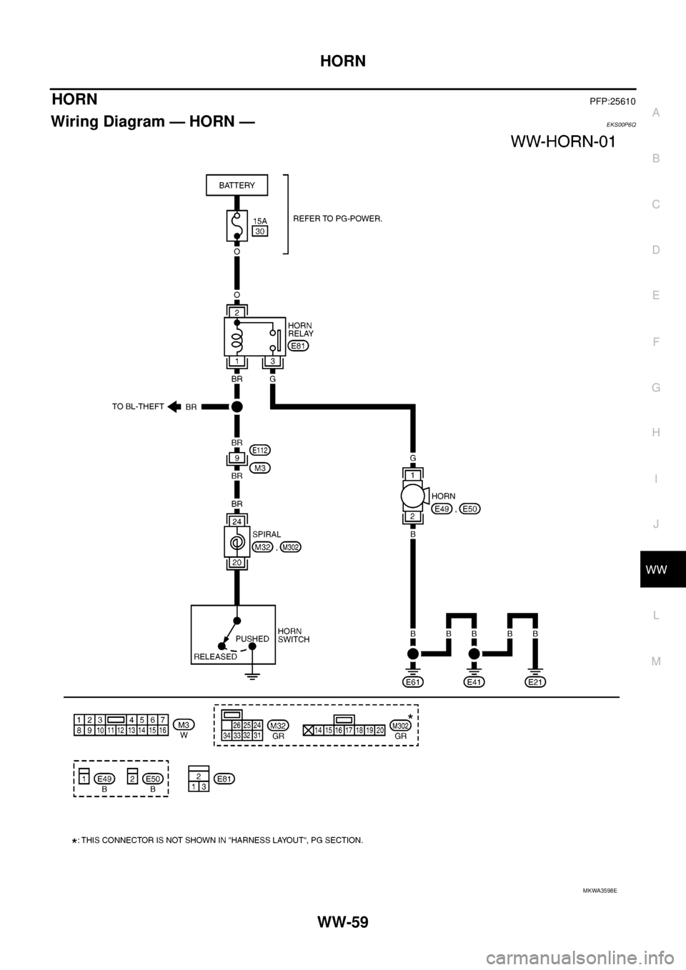
HORNPFP:25610
Wiring Diagram — HORN —EKS00P6Q
MKWA3598E
Page 3171 of 3171

WW-60
HORN
Removal and Installation of Horn
EKS00P6R
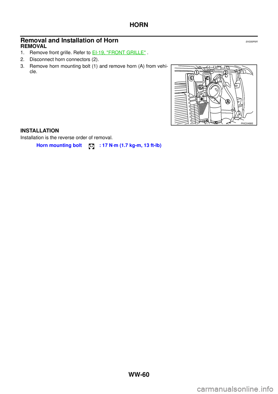
REMOVAL
1. Remove front grille. Refer toEI-19, "FRONT GRILLE".
2. Disconnect horn connectors (2).
3. Remove horn mounting bolt (1) and remove horn (A) from vehi-
cle.
INSTALLATION
Installation is the reverse order of removal.
PKIC0466E
Horn mounting bolt : 17 N·m (1.7 kg-m, 13 ft-lb)