2005 NISSAN NAVARA horn
[x] Cancel search: hornPage 1816 of 3171
![NISSAN NAVARA 2005 Repair Workshop Manual CAN COMMUNICATION
LAN-39
[CAN]
C
D
E
F
G
H
I
J
L
MA
B
LAN
Input/output signal chart
T: Transmit R: Receive
Signals ECMNAVI
control
unitDiffer-
ential
lock
control
unitFront air
con-
trol
*1BCMCombi-
n NISSAN NAVARA 2005 Repair Workshop Manual CAN COMMUNICATION
LAN-39
[CAN]
C
D
E
F
G
H
I
J
L
MA
B
LAN
Input/output signal chart
T: Transmit R: Receive
Signals ECMNAVI
control
unitDiffer-
ential
lock
control
unitFront air
con-
trol
*1BCMCombi-
n](/manual-img/5/57362/w960_57362-1815.png)
CAN COMMUNICATION
LAN-39
[CAN]
C
D
E
F
G
H
I
J
L
MA
B
LAN
Input/output signal chart
T: Transmit R: Receive
Signals ECMNAVI
control
unitDiffer-
ential
lock
control
unitFront air
con-
trol
*1BCMCombi-
nation
meterTrans-
fer con-
trol unitABS
actua-
tor and
electric
unit
(control
unit)IPDM
E/R
A/C compressor request signal TR
ASCD CRUISE lamp signal T R
ASCD SET lamp signal T R
Cooling fan speed request signal TR
Engine coolant temperature signal T R R
Engine speed signal T R R R
Engine status signal T R R
Fuel consumption monitor signalTR
RT
Glow indicator signal T R
Glow relay signal T R
Malfunction indicator signal T R
A/C switch/indicator signal T
R
*2
Differential lock indicator signal T R
Differential lock switch signal T R
PTC heater signal
*3RT
A/C switch signal R
R
*2T
Buzzer output signal T R
Day time running light request signal R T R R
Door switch signal T R R
Front fog light request signal R T R R
Front wiper request signal T R
High beam request signal T R R
Horn chirp signal T R
Low beam request signal T R
Position light request signal T R R
Rear fog light request signal R T R
Rear window defogger switch signal R T R
Sleep wake up signal T R R
Theft warning horn request signal T R
Trailer lamp signal T R
Turn indicator signal T R
Distance to empty signal R T
Fuel level low warning signal R T
4WD shift switch signal R T
ABS warning lamp signal R T
Stop lamp switch signalRT
Page 1819 of 3171
![NISSAN NAVARA 2005 Repair Workshop Manual LAN-42
[CAN]
CAN COMMUNICATION
Engine coolant temperature signal T R R
Engine speed signal T R R R R
Engine status signal T R R
Fuel consumption monitor signalTR
RT
Glow indicator signal T R
Glow rela NISSAN NAVARA 2005 Repair Workshop Manual LAN-42
[CAN]
CAN COMMUNICATION
Engine coolant temperature signal T R R
Engine speed signal T R R R R
Engine status signal T R R
Fuel consumption monitor signalTR
RT
Glow indicator signal T R
Glow rela](/manual-img/5/57362/w960_57362-1818.png)
LAN-42
[CAN]
CAN COMMUNICATION
Engine coolant temperature signal T R R
Engine speed signal T R R R R
Engine status signal T R R
Fuel consumption monitor signalTR
RT
Glow indicator signal T R
Glow relay signal T R
Malfunction indicator signal T R
Wide open throttle position signal T R
A/T fluid temperature sensor signal T R
A/T position indicator lamp signal T R R
OD OFF indicator lamp signal T R
Output shaft revolution signal R T R
Turbine revolution signal R T
A/C switch/indicator signal T R
Differential lock indicator signal T R
Differential lock switch signal T R
PTC heater signal
*RT
A/C switch signal R R T
Buzzer output signal T R
Day time running light request signal R T R R
Door switch signal T R R
Front fog light request signal R T R R
Front wiper request signal T R
High beam request signal T R R
Horn chirp signalTR
Low beam request signal T R
Position light request signal T R R
Rear fog light request signal R T R
Rear window defogger switch signal R T R
Sleepwakeupsignal T R R
Theft warning horn request signal T R
Trailer lamp signal T R
Turn indicator signal T R
1st position switch signal R T
Distance to empty signal R T
Fuel level low warning signal R T
Overdrive control switch signal R T
Stop lamp switch signal R TSignals ECM TCMNAVI
con-
trol
unitDiffer-
ential
lock
con-
trol
unitFront
air
controlBCMCom-
bina-
tion
meterTrans-
fer
con-
trol
unitABS
actua-
tor and
elec-
tric unit
(con-
trol
unit)IPDM
E/R
Page 2280 of 3171
DESCRIPTION
MA-5
C
D
E
F
G
H
I
J
K
MA
B
MA
DESCRIPTIONPFP:00000
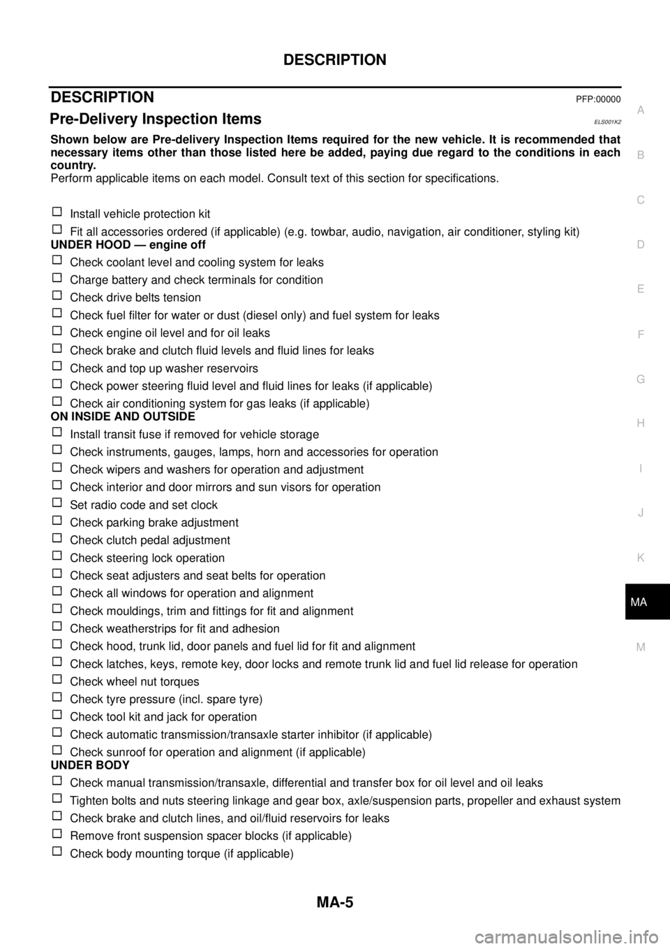
Pre-Delivery Inspection ItemsELS001K2
Shown below are Pre-delivery Inspection Items required for the new vehicle. It is recommended that
necessary items other than those listed here be added, paying due regard to the conditions in each
country.
Perform applicable items on each model. Consult text of this section for specifications.
Install vehicle protection kit
Fit all accessories ordered (if applicable) (e.g. towbar, audio, navigation, air conditioner, styling kit)
UNDER HOOD — engine off
Check coolant level and cooling system for leaks
Charge battery and check terminals for condition
Check drive belts tension
Check fuel filter for water or dust (diesel only) and fuel system for leaks
Check engine oil level and for oil leaks
Check brake and clutch fluid levels and fluid lines for leaks
Check and top up washer reservoirs
Check power steering fluid level and fluid lines for leaks (if applicable)
Check air conditioning system for gas leaks (if applicable)
ON INSIDE AND OUTSIDE
Install transit fuse if removed for vehicle storage
Check instruments, gauges, lamps, horn and accessories for operation
Check wipers and washers for operation and adjustment
Check interior and door mirrors and sun visors for operation
Set radio code and set clock
Check parking brake adjustment
Check clutch pedal adjustment
Check steering lock operation
Check seat adjusters and seat belts for operation
Check all windows for operation and alignment
Check mouldings, trim and fittings for fit and alignment
Check weatherstrips for fit and adhesion
Check hood, trunk lid, door panels and fuel lid for fit and alignment
Check latches, keys, remote key, door locks and remote trunk lid and fuel lid release for operation
Check wheel nut torques
Check tyre pressure (incl. spare tyre)
Check tool kit and jack for operation
Check automatic transmission/transaxle starter inhibitor (if applicable)
Check sunroof for operation and alignment (if applicable)
UNDER BODY
Check manual transmission/transaxle, differential and transfer box for oil level and oil leaks
Tighten bolts and nuts steering linkage and gear box, axle/suspension parts, propeller and exhaust system
Check brake and clutch lines, and oil/fluid reservoirs for leaks
Remove front suspension spacer blocks (if applicable)
Check body mounting torque (if applicable)
Page 2296 of 3171
ENGINE MAINTENANCE
MA-21
C
D
E
F
G
H
I
J
K
MA
B
MA
11. Repeat step 10 three times.
12. If sound is heard, bleed air from cooling system by repeating steps 3 through 6 until engine coolant level
no longer drops.
FLUSHING COOLING SYSTEM
1. Fill radiator with water until water spills from the air relief hole, then close air relief plug. Fill radiator and
reservoir tank with water and reinstall radiator cap and reservoir tank cap.
2. Run engine and warm it up to normal operating temperature.
3. Rev engine two or three times under no-load.
4. Stop engine and wait until it cools down.
5. Drain water from the system. Refer toMA-19, "
DRAINING ENGINE COOLANT".
6. Repeat steps 1 through 5 until clear water begins to drain from radiator.
Checking Cooling SystemELS001JR
WARNING:
Never remove the radiator cap and reservoir tank cap when the engine is hot. Serious burns could
occur from high pressure engine coolant escaping from the radiator and the reservoir tank. Wrap a
thick cloth around the cap. Slowly turn it a quarter turn to allow built-up pressure to escape. Carefully
remove the cap by turning it all the way.
CHECKING COOLING SYSTEM HOSES
Check hoses for improper attachment, leaks, cracks, damage, loose connections, chafing and deterioration.
CHECKING RADIATOR
Check radiator for mud or clogging. If necessary, clean radiator as follows.
lBe careful not to bend or damage the radiator fins.
lWhen radiator is cleaned without removal, remove all surrounding parts such as cooling fan, radiator
shroud and horns. Then tape the harness and connectors to prevent water from entering.
1. Apply water by hose to the back side of the radiator core vertically downwards.
2. Apply water again to all radiator core surface once per minute.
3. Stop washing if any stains no longer flow out from the radiator.
4. Blow air into the back side of radiator core vertically downwards.
lUse compressed air lower than 490 kpa (4.9 bar, 5 kg/cm2, 71psi) and keep distance more than 30
cm(11.8 in).
5. Blow air again into all the radiator core surface once per minute until no water sprays out.
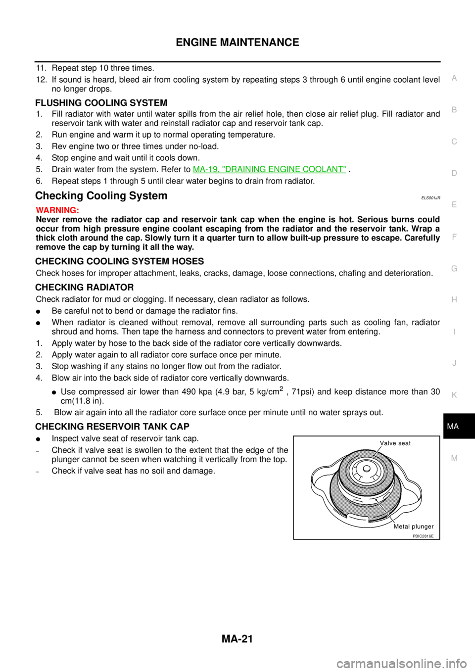
CHECKING RESERVOIR TANK CAP
lInspect valve seat of reservoir tank cap.
–Check if valve seat is swollen to the extent that the edge of the
plunger cannot be seen when watching it vertically from the top.
–Check if valve seat has no soil and damage.
PBIC2816E
Page 2547 of 3171

PG-18
IPDM E/R (INTELLIGENT POWER DISTRIBUTION MODULE ENGINE ROOM)
5. Touch “RECORD” while monitoring to record the status of the item being monitored. To stop recording,
touch “STOP”.
All Signals, Main Signals, Selection From Menu
NOTE:
Perform monitoring of IPDM E/R data with the ignition switch ON. When the ignition switch is in ACC position,
display may not be correct.
CAN DIAG SUPPORT MNTR
Refer toLAN-15, "CAN Diagnostic Support Monitor".
ACTIVE TEST
Operation Procedure
1. Touch “ACTIVE TEST” on “SELECT DIAG-MODE” screen.
2. Touch item to be tested, and check operation.
3. Touch “START”.
4. Touch “STOP” while testing to stop the operation.
Item nameCONSULT-II
screen displayDisplay or unitMonitor item selection
Description
ALL
SIGNALSMAIN
SIGNALSSELECTION
FROM MENU
Motor fan requestMOTOR FAN
REQ1/2/3/4 X X X Signal status input from ECM
A/C compressor
requestAC COMP REQ ON/OFF X X X Signal status input from ECM
Tail & clear
requestTAIL & CLR REQ ON/OFF X X X Signal status input from BCM
Headlamp LO
requestHL LO REQ ON/OFF X X X Signal status input from BCM
Headlamp HI
requestHL HI REQ ON/OFF X X X Signal status input from BCM
Front fog lamp
requestFR FOG REQ ON/OFF X X X Signal status input from BCM
Headlamp washer
requestHL WASHER
REQON/OFF X X Signal from input from BCM
Front wiper
requestFR WIP REQSTOP/1LOW/
LOW/HIX X X Signal status input from BCM
Wiper auto stopWIP AUTO
STOPACT P/STOP P X X X Output status of IPDM E/R
Wiper protection WIP PROT OFF/BLOCK X X X Control status of IPDM E/R
Starter request ST RLY REQ ON/OFF X X
Status of input signal
NOTE
Ignition relay
statusIGN RLY ON/OFF X X XIgnition relay status monitored
with IPDM E/R
Rear defogger
requestRR DEF REQ ON/OFF X X X Signal status input from BCM
Oil pressure
switchOIL P SW OPEN/CLOSE X XSignal status input from IPDM
E/R
Hood switch HOOD SW OFF XSignal status input from IPDM
E/R (function is not enabled)
Theft warning
horn requestTHFT HRN REQ ON/OFF X X Signal status input from BCM
Horn chirp HORN CHIRP ON/OFF X X Output status of IPDM E/R
Page 2548 of 3171
IPDM E/R (INTELLIGENT POWER DISTRIBUTION MODULE ENGINE ROOM)
PG-19
C
D
E
F
G
H
I
J
L
MA
B
PG
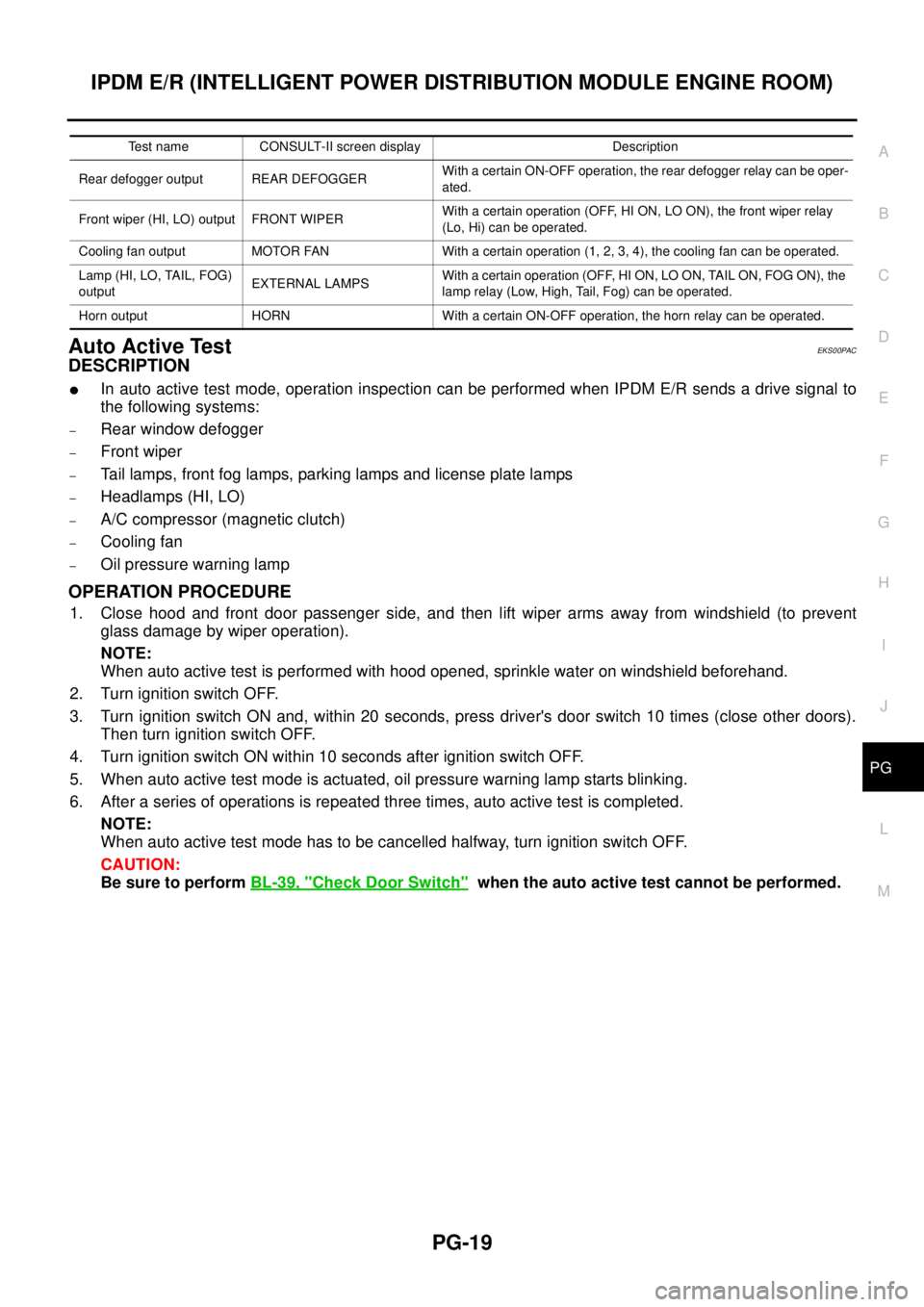
Auto Active TestEKS00PAC
DESCRIPTION
lIn auto active test mode, operation inspection can be performed when IPDM E/R sends a drive signal to
the following systems:
–Rear window defogger
–Front wiper
–Tail lamps, front fog lamps, parking lamps and license plate lamps
–Headlamps (HI, LO)
–A/C compressor (magnetic clutch)
–Cooling fan
–Oil pressure warning lamp
OPERATION PROCEDURE
1. Close hood and front door passenger side, and then lift wiper arms away from windshield (to prevent
glass damage by wiper operation).
NOTE:
When auto active test is performed with hood opened, sprinkle water on windshield beforehand.
2. Turn ignition switch OFF.
3. Turn ignition switch ON and, within 20 seconds, press driver's door switch 10 times (close other doors).
Then turn ignition switch OFF.
4. Turn ignition switch ON within 10 seconds after ignition switch OFF.
5. When auto active test mode is actuated, oil pressure warning lamp starts blinking.
6. After a series of operations is repeated three times, auto active test is completed.
NOTE:
When auto active test mode has to be cancelled halfway, turn ignition switch OFF.
CAUTION:
Be sure to performBL-39, "
Check Door Switch"when the auto active test cannot be performed.
Test name CONSULT-II screen display Description
Rear defogger output REAR DEFOGGERWith a certain ON-OFF operation, the rear defogger relay can be oper-
ated.
Front wiper (HI, LO) output FRONT WIPERWith a certain operation (OFF, HI ON, LO ON), the front wiper relay
(Lo, Hi) can be operated.
Cooling fan output MOTOR FAN With a certain operation (1, 2, 3, 4), the cooling fan can be operated.
Lamp (HI, LO, TAIL, FOG)
outputEXTERNAL LAMPSWith a certain operation (OFF, HI ON, LO ON, TAIL ON, FOG ON), the
lamp relay (Low, High, Tail, Fog) can be operated.
Horn output HORN With a certain ON-OFF operation, the horn relay can be operated.
Page 2598 of 3171
HARNESS
PG-69
C
D
E
F
G
H
I
J
L
MA
B
PG
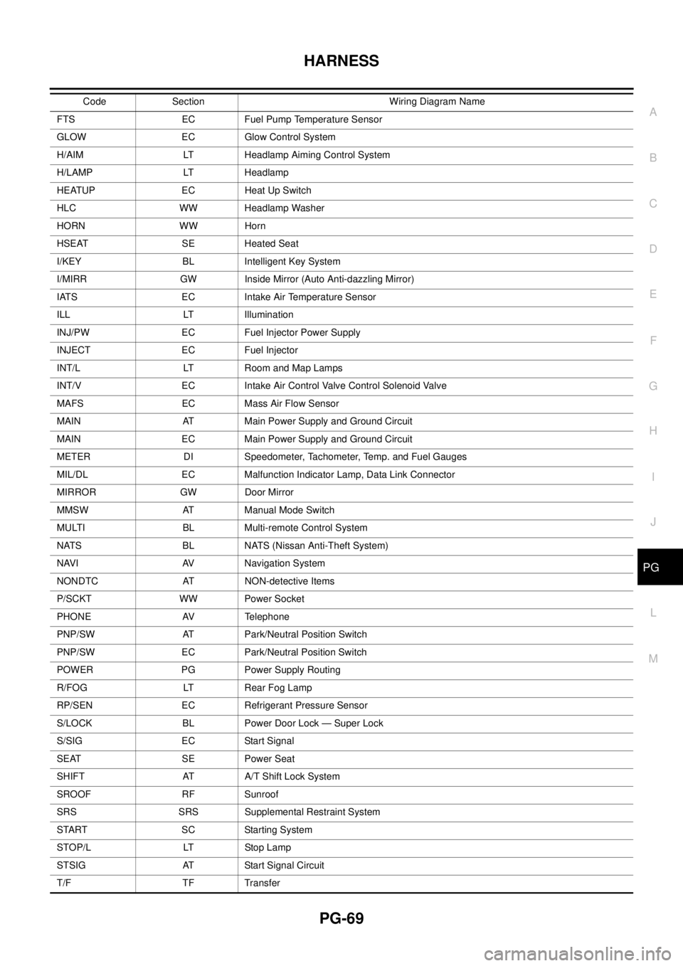
FTS EC Fuel Pump Temperature Sensor
GLOW EC Glow Control System
H/AIM LT Headlamp Aiming Control System
H/LAMP LT Headlamp
HEATUP EC Heat Up Switch
HLC WW Headlamp Washer
HORN WW Horn
HSEAT SE Heated Seat
I/KEY BL Intelligent Key System
I/MIRR GW Inside Mirror (Auto Anti-dazzling Mirror)
IATS EC Intake Air Temperature Sensor
ILL LT Illumination
INJ/PW EC Fuel Injector Power Supply
INJECT EC Fuel Injector
INT/L LT Room and Map Lamps
INT/V EC Intake Air Control Valve Control Solenoid Valve
MAFS EC Mass Air Flow Sensor
MAIN AT Main Power Supply and Ground Circuit
MAIN EC Main Power Supply and Ground Circuit
METER DI Speedometer, Tachometer, Temp. and Fuel Gauges
MIL/DL EC Malfunction Indicator Lamp, Data Link Connector
MIRROR GW Door Mirror
MMSW AT Manual Mode Switch
MULTI BL Multi-remote Control System
NATS BL NATS (Nissan Anti-Theft System)
NAVI AV Navigation System
NONDTC AT NON-detective Items
P/SCKT WW Power Socket
PHONE AV Telephone
PNP/SW AT Park/Neutral Position Switch
PNP/SW EC Park/Neutral Position Switch
POWER PG Power Supply Routing
R/FOG LT Rear Fog Lamp
RP/SEN EC Refrigerant Pressure Sensor
S/LOCK BL Power Door Lock — Super Lock
S/SIG EC Start Signal
SEAT SE Power Seat
SHIFT AT A/T Shift Lock System
SROOF RF Sunroof
SRS SRS Supplemental Restraint System
START SC Starting System
STOP/L LT Stop Lamp
STSIG AT Start Signal Circuit
T/F TF TransferCode Section Wiring Diagram Name
Page 2945 of 3171
SRS-36
DRIVER AIR BAG MODULE
DRIVER AIR BAG MODULE
PFP:K8510
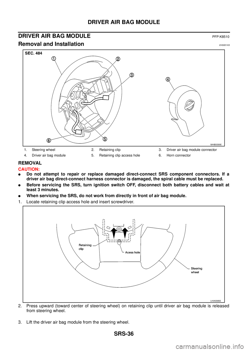
Removal and InstallationEHS001XS
REMOVAL
CAUTION:
lDo not attempt to repair or replace damaged direct-connect SRS component connectors. If a
driver air bag direct-connect harness connector is damaged, the spiral cable must be replaced.
lBefore servicing the SRS, turn ignition switch OFF, disconnect both battery cables and wait at
least 3 minutes.
lWhen servicing the SRS, do not work from directly in front of air bag module.
1. Locate retaining clip access hole and insert screwdriver.
2. Press upward (toward center of steering wheel) on retaining clip until driver air bag module is released
from steering wheel.
3. Lift the driver air bag module from the steering wheel.
1. Steering wheel 2. Retaining clip 3. Driver air bag module connector
4. Driver air bag module 5. Retaining clip access hole 6. Horn connector
MHIB0099E
LHIA0085E