2005 NISSAN NAVARA charging
[x] Cancel search: chargingPage 1 of 3171
MODELD40 SERIES
2005 NISSAN EUROPE S.A.S.
All rights reserved. No part of this Electronic Service Manual may be reproduced or stored in a retrieval system, or transmitted in any
form, or by any means, electronic, mechanical, photocopying, recording or otherwise, without the prior written permission of Nissan
Europe S.A.S., Paris, France.
A GENERAL INFORMATION
B ENGINE
C TRANSMISSION/TRANSAXLE
D DRIVELINE/AXLE
E SUSPENSION F BRAKES
G STEERING H RESTRAINTS
I BODY
J AIR CONDITIONER
K ELECTRICAL
L MAINTENANCE
M INDEXGI General Information
EM Engine Mechanical
LU Engine Lubrication System
CO Engine Cooling System
EC Engine Control System
FL Fuel System
EX Exhaust System
ACC Accelerator Control System
CL Clutch
MTManualTransmission
AT Automatic Transmission
TF Transfer
PR Propeller Shaft
FFD Front Final Drive
RFD Rear Final Drive
FAX Front Axle
RAX Rear Axle
FSU Front Suspension
RSU Rear Suspension
WT Road Wheels & Tires
BR Brake System
PB Parking Brake System
BRC Brake Control System
PS Power Steering System
SB Seat Belts
SRS Supplemental Restraint System (SRS)
BL Body, Lock & Security System
GW Glasses, Window System & Mirrors
RF Roof
EI Exterior & Interior
IP Instrument Panel
SE Seat
ATC Automatic Air Conditioner
MTC Manual Air Conditioner
SC Starting & Charging System
LT Lighting System
DI Driver Information System
WW Wiper, Washer & Horn
BCS Body Control System
LAN LAN System
AV Audio, Visual & Telephone System
ACS Auto Cruise Control System
PG Power Supply, Ground & Circuit Elements
MA Maintenance
IDX Alphabetical Index
QUICK REFERENCE INDEX
A
B
C
D
E
F
G
H
I
J
K
L
M
Page 19 of 3171

A/T FLUID
AT-11
D
E
F
G
H
I
J
K
L
MA
B
AT
A/T FLUIDPFP:KLE40
Changing A/T FluidECS00FWD
1. Warm up ATF.
2. Stop engine.
3. Loosen level gauge bolt.
4. Remove A/T fluid level gauge.
5. Remove drain plug and drain ATF from drain hole.
6. Install drain plug gasket and drain plug to oil pan.
CAUTION:
Do not reuse drain plug gasket.
7. Tighten drain plug to the specified torque. Refer toAT-218,
"COMPONENTS".
8. Refill with new ATF. Always refill same volume with drained ATF.
lTo replace the ATF, pour in new ATF at A/T fluid charging pipe
with the engine idling and at the same time drain the old ATF
from A/T fluid cooler hose return side.
lWhen the color of the ATF coming out is about the same as the color of the new ATF, the replacement
is complete. The amount of new ATF to use should be 30 to 50% increase of the specified amount.
CAUTION:
lUse only Genuine NISSAN ATF Matic Fluid J. Do not mix with other ATF.
lUsing ATF other than Genuine NISSAN ATF Matic Fluid J will cause deterioration in driveability
and A/T durability, and may damage the A/T, which is not covered by the NISSAN new vehicle
warranty.
lWhen filling ATF, take care not to spillover heat generating parts such as exhaust.
9. Run engine at idle speed for 5 minutes.
10. Check A/T fluid level and condition. Refer toAT-12, "
Checking A/T Fluid". If ATF is still dirty, repeat step 2
through 9.
11. Install the removed A/T fluid level gauge into A/T fluid charging pipe.
12. Tighten level gauge bolt to the specified torque. Refer toAT- 2 4 7 , "
COMPONENTS". ATF: Genuine NISSAN ATF Matic Fluid J
Fluid capacity:
10.3 (9-1/8 lmp qt)
SCIA4896E
Page 20 of 3171

AT-12
A/T FLUID
Checking A/T Fluid
ECS00FWE
1. Warm up engine.
2. Check for A/T fluid leakage.
3. Loosen level gauge bolt.
4. Before driving, A/T fluid level can be checked at A/T fluid tem-
peratures of 30 to 50°C (86 to 122°F) using “COLD” range on A/
T fluid level gauge as follows.
a. Park vehicle on level surface and set parking brake.
b. Start engine and move selector lever through each gear posi-
tion. Leave selector lever in “P” position.
c. Check A/T fluid level with engine idling.
d. Remove A/T fluid level gauge and wipe clean with lint-free
paper.
CAUTION:
When wiping away A/T fluid level gauge, always use lint-
free paper, not a cloth one.
e. Reinsert A/T fluid level gauge into A/T fluid charging pipe as far as it will go.
CAUTION:
To check A/T fluid level, insert A/T fluid level gauge until the cap contacts the end of A/T fluid
charging pipe, with A/T fluid level gauge reversed from the normal attachment conditions.
f. Remove A/T fluid level gauge and note reading. If reading is at low side of range, add ATF to A/T fluid
charging pipe.
CAUTION:
Do not overfill.
5. Drive vehicle for approximately 5 minutes in urban areas.
6. Make the A/T fluid temperature approximately 65°C(149°F).
NOTE:
A/T fluid level will be greatly affected by temperature as shown in figure. Therefore, be certain to
perform operation while checking data with CONSULT-II.
a. Connect CONSULT-II to data link connector. Refer toAT-79, "
CONSULT-II SETTING PROCEDURE".
b. Select “MAIN SIGNALS” in “DATA MONITOR” mode for “A/T” with CONSULT-II.
c. Readthevalueof“ATFTEMP1”.
7. Recheck A/T fluid level at A/T fluid temperatures of approximately 65°C(149°F)using“HOT”rangeonA/
T fluid level gauge.
SCIA7120E
SLIA0016E
Page 21 of 3171
A/T FLUID
AT-13
D
E
F
G
H
I
J
K
L
MA
B
AT
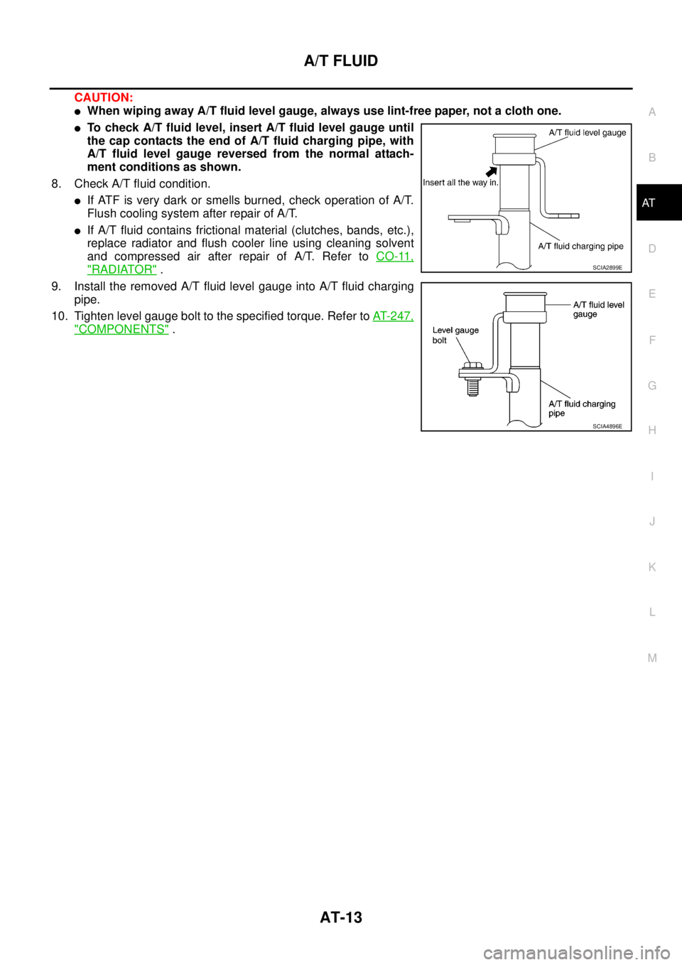
CAUTION:
lWhen wiping away A/T fluid level gauge, always use lint-free paper, not a cloth one.
lTo check A/T fluid level, insert A/T fluid level gauge until
the cap contacts the end of A/T fluid charging pipe, with
A/T fluid level gauge reversed from the normal attach-
ment conditions as shown.
8. Check A/T fluid condition.
lIf ATF is very dark or smells burned, check operation of A/T.
Flush cooling system after repair of A/T.
lIf A/T fluid contains frictional material (clutches, bands, etc.),
replace radiator and flush cooler line using cleaning solvent
and compressed air after repair of A/T. Refer toCO-11,
"RADIATOR".
9. Install the removed A/T fluid level gauge into A/T fluid charging
pipe.
10. Tighten level gauge bolt to the specified torque. Refer toAT-247,
"COMPONENTS".
SCIA2899E
SCIA4896E
Page 255 of 3171
TRANSMISSION ASSEMBLY
AT-247
D
E
F
G
H
I
J
K
L
MA
B
AT
TRANSMISSION ASSEMBLYPFP:31020
Removal and InstallationECS00HR4
COMPONENTS
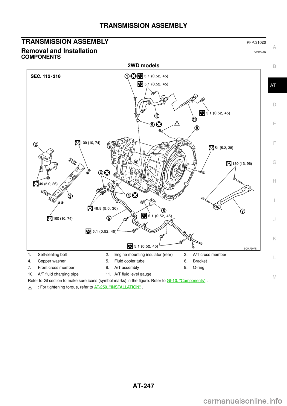
2WD models
SCIA7307E
1. Self-sealing bolt 2. Engine mounting insulator (rear) 3. A/T cross member
4. Copper washer 5. Fluid cooler tube 6. Bracket
7. Front cross member 8. A/T assembly 9. O-ring
10. A/T fluid charging pipe 11. A/T fluid level gauge
Refer to GI section to make sure icons (symbol marks) in the figure. Refer toGI-10, "
Components".
: For tightening torque, refer toAT- 2 5 0 , "
INSTALLATION".
Page 256 of 3171
AT-248
TRANSMISSION ASSEMBLY
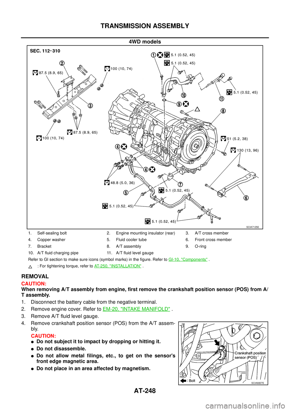
4WD models
REMOVAL
CAUTION:
When removing A/T assembly from engine, first remove the crankshaft position sensor (POS) from A/
T assembly.
1. Disconnect the battery cable from the negative terminal.
2. Remove engine cover. Refer toEM-20, "
INTAKE MANIFOLD".
3. Remove A/T fluid level gauge.
4. Remove crankshaft position sensor (POS) from the A/T assem-
bly.
CAUTION:
lDo not subject it to impact by dropping or hitting it.
lDo not disassemble.
lDo not allow metal filings, etc., to get on the sensor's
front edge magnetic area.
lDo not place in an area affected by magnetism.
SCIA7125E
1. Self-sealing bolt 2. Engine mounting insulator (rear) 3. A/T cross member
4. Copper washer 5. Fluid cooler tube 6. Front cross member
7. Bracket 8. A/T assembly 9. O-ring
10. A/T fluid charging pipe 11. A/T fluid level gauge
Refer to GI section to make sure icons (symbol marks) in the figure. Refer toGI-10, "
Components".
: For tightening torque, refer toAT-250, "
INSTALLATION".
SCIA6827E
Page 257 of 3171

TRANSMISSION ASSEMBLY
AT-249
D
E
F
G
H
I
J
K
L
MA
B
AT
5. Remove front valance center, engine undercover front, engine under cover middle and engine under
coverrear.RefertoEI-15, "
FRONT BUMPER".
6. Remove front cross member.
7. Remove main muffler. Refer toEX-2, "
EXHAUST SYSTEM".
8. Remove rear propeller shaft. Refer toPR-8, "
Removal and Installation".
9. Remove front propeller shaft. Refer toPR-4, "
Removal and Installation".
10. Remove starter motor. Refer toSC-31, "
Removal and Installation".
11. Remove control cable and bracket. Refer toAT- 2 1 0 , "
Control Cable Removal and Installation".
12. Disconnect fluid cooler tube.
13. Remove A/T fluid charging pipe from A/T assembly.
14. Remove O-ring from A/T fluid charging pipe.
15. Plug up openings such as A/T fluid charging pipe hole, etc.
16. Remove rear plate cover from rear plate.
17. Turn crankshaft to access and remove the four bolts for drive
plate and torque converter.
CAUTION:
When turning crankshaft, turn it clockwise as viewed from
the front of engine.
18. Support A/T assembly using a transmission jack.
CAUTION:
When setting transmission jack, be careful not to allow it to
collide against drain plug.
19. Remove protector (fuel tube), and then disconnect fuel tubes.
Refer toFL-7, "
FUEL COOLER". (4WD models)
20. Remove A/T cross member.
21. Remove engine mounting insulator (rear) from A/T assembly.
22. Disconnect the following:
lA/T assembly harness connector
lATP switch connector
l4LO switch connector
lWait detection switch connector
lTransfer control device connector
23. Support transfer assembly using a transmission jack. (4WD models)
24. Remove the wiring harness from bracket.
25. Remove bolts fixing A/T assembly to engine assembly.
26. Remove A/T assembly from the vehicle.
CAUTION:
lSecure torque converter to prevent it from dropping.
lSecure A/T assembly to a transmission jack.
27. Remove A/T air breather hose. Refer toAT- 2 4 3 , "
AIR
BREATHER HOSE".
28. Remove transfer assembly from A/T assembly. Refer toT F - 111 ,
"Removal and Installation". (4WD models)
SCIA6828E
SCIA6927E
SCIA2203E
Page 335 of 3171
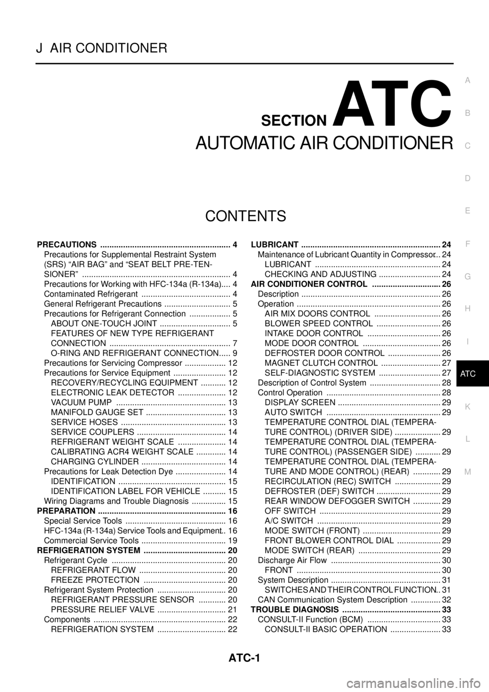
ATC-1
AUTOMATIC AIR CONDITIONER
J AIR CONDITIONER
CONTENTS
C
D
E
F
G
H
I
K
L
M
SECTIONAT C
A
B
AT C
AUTOMATIC AIR CONDITIONER
PRECAUTIONS .......................................................... 4
Precautions for Supplemental Restraint System
(SRS)“AIRBAG”and“SEATBELTPRE-TEN-
SIONER” .................................................................. 4
Precautions for Working with HFC-134a (R-134a)..... 4
Contaminated Refrigerant ........................................ 4
General Refrigerant Precautions .............................. 5
Precautions for Refrigerant Connection ................... 5
ABOUT ONE-TOUCH JOINT ................................ 5
FEATURES OF NEW TYPE REFRIGERANT
CONNECTION ...................................................... 7
O-RING AND REFRIGERANT CONNECTION..... 9
Precautions for Servicing Compressor ................... 12
Precautions for Service Equipment ........................ 12
RECOVERY/RECYCLING EQUIPMENT ............ 12
ELECTRONIC LEAK DETECTOR ...................... 12
VACUUM PUMP ................................................. 13
MANIFOLD GAUGE SET .................................... 13
SERVICE HOSES ............................................... 13
SERVICE COUPLERS ........................................ 14
REFRIGERANT WEIGHT SCALE ...................... 14
CALIBRATING ACR4 WEIGHT SCALE .............. 14
CHARGING CYLINDER ...................................... 14
Precautions for Leak Detection Dye ....................... 14
IDENTIFICATION ................................................ 15
IDENTIFICATION LABEL FOR VEHICLE ........... 15
Wiring Diagrams and Trouble Diagnosis ................ 15
PREPARATION ......................................................... 16
Special Service Tools ............................................. 16
HFC-134a (R-134a) Service Tools and Equipment... 16
Commercial Service Tools ...................................... 19
REFRIGERATION SYSTEM ..................................... 20
Refrigerant Cycle ................................................... 20
REFRIGERANT FLOW ....................................... 20
FREEZE PROTECTION ..................................... 20
Refrigerant System Protection ............................... 20
REFRIGERANT PRESSURE SENSOR ............. 20
PRESSURE RELIEF VALVE ............................... 21
Components ........................................................... 22
REFRIGERATION SYSTEM ............................... 22LUBRICANT .............................................................. 24
Maintenance of Lubricant Quantity in Compressor... 24
LUBRICANT ........................................................ 24
CHECKING AND ADJUSTING ............................ 24
AIR CONDITIONER CONTROL ............................... 26
Description .............................................................. 26
Operation ................................................................ 26
AIR MIX DOORS CONTROL .............................. 26
BLOWER SPEED CONTROL ............................. 26
INTAKE DOOR CONTROL ................................. 26
MODE DOOR CONTROL ................................... 26
DEFROSTER DOOR CONTROL ........................ 26
MAGNET CLUTCH CONTROL ........................... 27
SELF-DIAGNOSTIC SYSTEM ............................ 27
Description of Control System ................................ 28
Control Operation ................................................... 28
DISPLAY SCREEN .............................................. 29
AUTO SWITCH ................................................... 29
TEMPERATURE CONTROL DIAL (TEMPERA-
TURE CONTROL) (DRIVER SIDE) ..................... 29
TEMPERATURE CONTROL DIAL (TEMPERA-
TURE CONTROL) (PASSENGER SIDE) ............ 29
TEMPERATURE CONTROL DIAL (TEMPERA-
TURE AND MODE CONTROL) (REAR) ............. 29
RECIRCULATION (REC) SWITCH ..................... 29
DEFROSTER (DEF) SWITCH ............................. 29
REAR WINDOW DEFOGGER SWITCH ............. 29
OFF SWITCH ...................................................... 29
A/C SWITCH ....................................................... 29
MODE SWITCH (FRONT) ................................... 29
FRONT BLOWER CONTROL DIAL .................... 29
MODE SWITCH (REAR) ..................................... 29
Discharge Air Flow ................................................. 30
FRONT ................................................................ 30
System Description ................................................. 31
SWITCHES AND THEIR CONTROL FUNCTION... 31
CAN Communication System Description .............. 32
TROUBLE DIAGNOSIS ............................................ 33
CONSULT-II Function (BCM) ................................. 33
CONSULT-II BASIC OPERATION ....................... 33